Page 1794 of 3371
FUEL PUMP CIRCUIT
EC-603
C
D
E
F
G
H
I
J
K
L
MA
EC
Revision: August 20072004 QX56
Specification data are reference values and are measured between each terminal and ground.
CAUTION:
Do not use ECM ground terminals when measuring input/output voltage. Doing so may result in dam-
age to the ECM's transistor. Use a ground other than ECM terminals, such as the ground.
Diagnostic ProcedureUBS00HDE
1. CHECK OVERALL FUNCTION
1. Turn ignition switch ON.
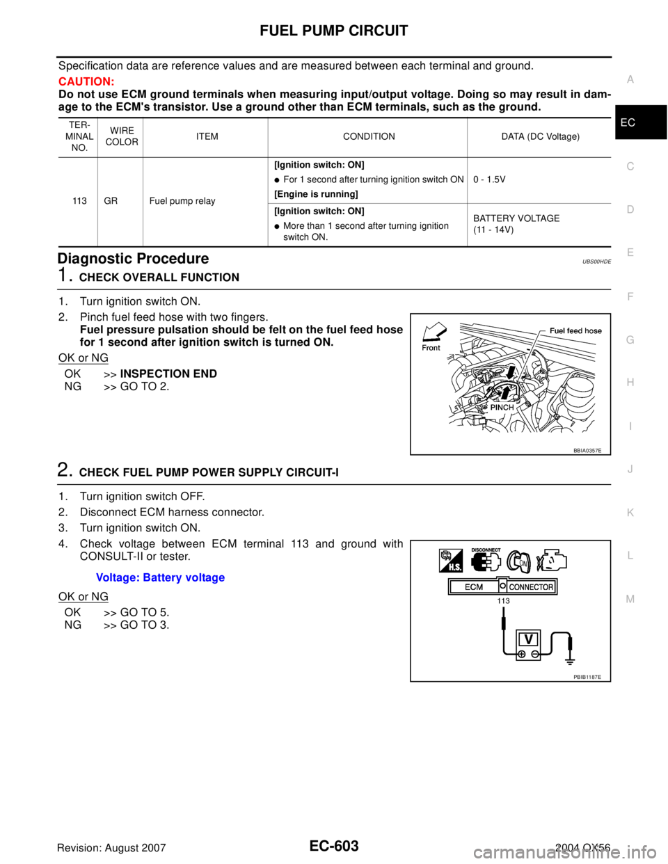
2. Pinch fuel feed hose with two fingers.
Fuel pressure pulsation should be felt on the fuel feed hose
for 1 second after ignition switch is turned ON.
OK or NG
OK >>INSPECTION END
NG >> GO TO 2.
2. CHECK FUEL PUMP POWER SUPPLY CIRCUIT-I
1. Turn ignition switch OFF.
2. Disconnect ECM harness connector.
3. Turn ignition switch ON.
4. Check voltage between ECM terminal 113 and ground with
CONSULT-II or tester.
OK or NG
OK >> GO TO 5.
NG >> GO TO 3.
TER-
MINAL
NO.WIRE
COLORITEM CONDITION DATA (DC Voltage)
113 GR Fuel pump relay[Ignition switch: ON]
�For 1 second after turning ignition switch ON
[Engine is running]0 - 1.5V
[Ignition switch: ON]
�More than 1 second after turning ignition
switch ON.BATTERY VOLTAGE
(11 - 14V)
BBIA0357E
Voltage: Battery voltage
PBIB11 87 E
Page 1795 of 3371
EC-604Revision: August 2007
FUEL PUMP CIRCUIT
2004 QX56
3. CHECK FUEL PUMP POWER SUPPLY CIRCUIT-II
1. Turn ignition switch OFF.
2. Disconnect IPDM E/R harness connector E122.
3. Turn ignition switch ON.
4. Check voltage between IPDM E/R terminal 46 and ground with
CONSULT-II or tester.
OK or NG
OK >> GO TO 4.
NG >> GO TO 12.
4. DETECT MALFUNCTIONING PART
Check the following.
�Harness for open or short between IPDM E/R and ECM
>> Repair harness or connectors.
5. CHECK CONDENSER POWER SUPPLY CIRCUIT
1. Turn ignition switch OFF.
2. Reconnect all harness connectors disconnected.
3. Disconnect condenser harness connector.
4. Turn ignition switch ON.
5. Check voltage between condenser terminal 1 and ground with
CONSULT-II or tester.
6. Also check harness for short to ground and short to power.
OK or NG
OK >> GO TO 8.
NG >> GO TO 6.Voltage: Battery voltage
PBIB2084E
BBIA0388E
Voltage: Battery voltage should exist for 1 sec-
ond after ignition switch is turned ON.
PBIB0624E
Page 1796 of 3371
FUEL PUMP CIRCUIT
EC-605
C
D
E
F
G
H
I
J
K
L
MA
EC
Revision: August 20072004 QX56
6. CHECK 15A FUSE
1. Turn ignition switch OFF.
2. Disconnect 15A fuse.
3. Check 15A fuse.
OK or NG
OK >> GO TO 7.
NG >> Replace fuse.
7. CHECK CONDENSER POWER SUPPLY CIRCUIT-II FOR OPEN AND SHORT
1. Disconnect IPDM E/R harness connector E119.
2. Check harness continuity between IPDM E/R terminal 13 and condenser terminal 1.
Refer to Wiring Diagram.
3. Also check harness for short to ground and short to power.
OK or NG
OK >> GO TO 12.
NG >> Repair open circuit or short to ground or short to power in harness or connectors.
8. CHECK CONDENSER GROUND CIRCUIT FOR OPEN AND SHORT
1. Check harness continuity between condenser terminal 1 and ground.
Refer to Wiring Diagram.
2. Also check harness for short to power.
OK or NG
OK >> GO TO 9.
NG >> Repair open circuit or short to power in harness or connectors.
9. CHECK CONDENSER
Refer to EC-606, "
Component Inspection" .
OK or NG
OK >> GO TO 10.
NG >> Replace condenser.
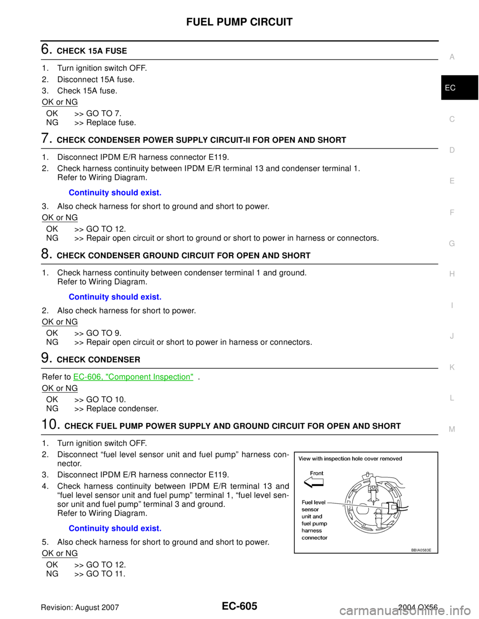
10. CHECK FUEL PUMP POWER SUPPLY AND GROUND CIRCUIT FOR OPEN AND SHORT
1. Turn ignition switch OFF.
2. Disconnect “fuel level sensor unit and fuel pump” harness con-
nector.
3. Disconnect IPDM E/R harness connector E119.
4. Check harness continuity between IPDM E/R terminal 13 and
“fuel level sensor unit and fuel pump” terminal 1, “fuel level sen-
sor unit and fuel pump” terminal 3 and ground.
Refer to Wiring Diagram.
5. Also check harness for short to ground and short to power.
OK or NG
OK >> GO TO 12.
NG >> GO TO 11.Continuity should exist.
Continuity should exist.
Continuity should exist.
BBIA0583E
Page 1797 of 3371
EC-606Revision: August 2007
FUEL PUMP CIRCUIT
2004 QX56
11 . DETECT MALFUNCTIONING PART
Check the following.
�Harness connectors E41, C1
�Harness for open or short between fuel pump and IPDM E/R
�Harness for open or short between fuel pump and ground
>> Repair open circuit or short to ground or short to power in harness or connectors.
12. CHECK INTERMITTENT INCIDENT
Refer to EC-127, "
TROUBLE DIAGNOSIS FOR INTERMITTENT INCIDENT" .
OK or NG
OK >> Replace IPDM E/R.
NG >> Repair or replace harness or connectors.
Component InspectionUBS00HDF
FUEL PUMP
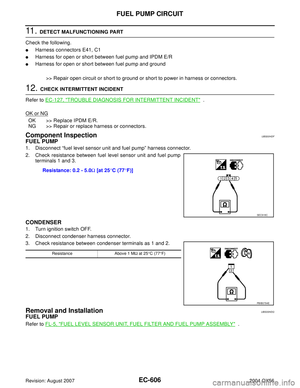
1. Disconnect “fuel level sensor unit and fuel pump” harness connector.
2. Check resistance between fuel level sensor unit and fuel pump
terminals 1 and 3.
CONDENSER
1. Turn ignition switch OFF.
2. Disconnect condenser harness connector.
3. Check resistance between condenser terminals as 1 and 2.
Removal and InstallationUBS00HDG
FUEL PUMP
Refer to FL-5, "FUEL LEVEL SENSOR UNIT, FUEL FILTER AND FUEL PUMP ASSEMBLY" . Resistance: 0.2 - 5.0Ω [at 25°C (77°F)]
SEC9 18 C
Resistance Above 1 MΩ at 25°C (77°F)
PBIB0794E
Page 1828 of 3371
EVAPORATIVE EMISSION SYSTEM
EC-637
C
D
E
F
G
H
I
J
K
L
MA
EC
Revision: August 20072004 QX56
EVAP SERVICE PORT
Positive pressure is delivered to the EVAP system through the EVAP
service port. If fuel vapor leakage in the EVAP system occurs, use a
leak detector to locate the leak.
Removal and InstallationUBS00HE0
EVAP CANISTER
Tighten EVAP canister as shown in the figure.
EVAP CANISTER VENT CONTROL VALVE
1. Turn EVAP canister vent control valve counterclockwise.
2. Remove the EVAP canister vent control valve.
Always replace O-ring with a new one.
How to Detect Fuel Vapor LeakageUBS00HE1
CAUTION:
�Do not use compressed air or a high pressure pump.
�Do not exceed 4.12 kPa (0.042 kg/cm2 , 0.6 psi) of pressure in EVAP system.
NOTE:
�Do not start engine.
�Improper installation of EVAP service port adapter to the EVAP service port may cause a leak.
SEF 4 62 UA
BBIA0349E
BBIA0350E
Page 1831 of 3371
EC-640Revision: August 2007
ON BOARD REFUELING VAPOR RECOVERY (ORVR)
2004 QX56
ON BOARD REFUELING VAPOR RECOVERY (ORVR)PFP:00032
System DescriptionUBS00HE2
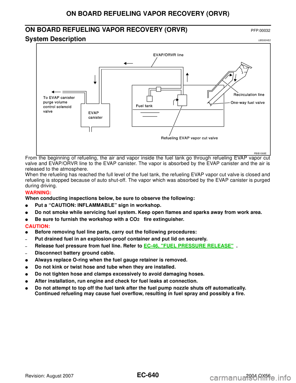
From the beginning of refueling, the air and vapor inside the fuel tank go through refueling EVAP vapor cut
valve and EVAP/ORVR line to the EVAP canister. The vapor is absorbed by the EVAP canister and the air is
released to the atmosphere.
When the refueling has reached the full level of the fuel tank, the refueling EVAP vapor cut valve is closed and
refueling is stopped because of auto shut-off. The vapor which was absorbed by the EVAP canister is purged
during driving.
WAR NIN G:
When conducting inspections below, be sure to observe the following:
�Put a “CAUTION: INFLAMMABLE” sign in workshop.
�Do not smoke while servicing fuel system. Keep open flames and sparks away from work area.
�Be sure to furnish the workshop with a CO2 fire extinguisher.
CAUTION:
�Before removing fuel line parts, carry out the following procedures:
–Put drained fuel in an explosion-proof container and put lid on securely.
–Release fuel pressure from fuel line. Refer to EC-46, "FUEL PRESSURE RELEASE" .
–Disconnect battery ground cable.
�Always replace O-ring when the fuel gauge retainer is removed.
�Do not kink or twist hose and tube when they are installed.
�Do not tighten hose and clamps excessively to avoid damaging hoses.
�After installation, run engine and check for fuel leaks at connection.
�Do not attempt to top off the fuel tank after the fuel pump nozzle shuts off automatically.
Continued refueling may cause fuel overflow, resulting in fuel spray and possibly a fire.
PBIB1068E
Page 1834 of 3371
ON BOARD REFUELING VAPOR RECOVERY (ORVR)
EC-643
C
D
E
F
G
H
I
J
K
L
MA
EC
Revision: August 20072004 QX56
7. CHECK REFUELING EVAP VAPOR CUT VALVE
Refer to EC-643, "
Component Inspection" .
OK or NG
OK >> GO TO 8.
NG >> Replace refueling EVAP vapor cut valve with fuel tank.
8. CHECK FUEL FILLER TUBE
Check filler neck tube and hose connected to the fuel tank for clogging, dents and cracks.
OK or NG
OK >> GO TO 9.
NG >> Replace fuel filler tube.
9. CHECK ONE-WAY FUEL VALVE-I
Check one-way valve for clogging.
OK or NG
OK >> GO TO 10.
NG >> Repair or replace one-way fuel valve with fuel tank.
10. CHECK ONE-WAY FUEL VALVE-II
1. Make sure that fuel is drained from the tank.
2. Remove fuel filler tube and hose.
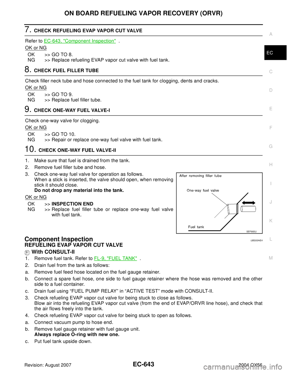
3. Check one-way fuel valve for operation as follows.
When a stick is inserted, the valve should open, when removing
stick it should close.
Do not drop any material into the tank.
OK or NG
OK >>INSPECTION END
NG >> Replace fuel filler tube or replace one-way fuel valve
with fuel tank.
Component InspectionUBS00HE4
REFUELING EVAP VAPOR CUT VALVE
With CONSULT-II
1. Remove fuel tank. Refer to FL-9, "FUEL TANK" .
2. Drain fuel from the tank as follows:
a. Remove fuel feed hose located on the fuel gauge retainer.
b. Connect a spare fuel hose, one side to fuel gauge retainer where the hose was removed and the other
side to a fuel container.
c. Drain fuel using “FUEL PUMP RELAY” in “ACTIVE TEST” mode with CONSULT-II.
3. Check refueling EVAP vapor cut valve for being stuck to close as follows.
Blow air into the refueling EVAP vapor cut valve (from the end of EVAP/ORVR line hose), and check that
the air flows freely into the tank.
4. Check refueling EVAP vapor cut valve for being stuck to open as follows.
a. Connect vacuum pump to hose end.
b. Remove fuel gauge retainer with fuel gauge unit.
Always replace O-ring with new one.
c. Put fuel tank upside down.
SEF 6 65 U
Page 1835 of 3371
![INFINITI QX56 2004 Factory Service Manual EC-644Revision: August 2007
ON BOARD REFUELING VAPOR RECOVERY (ORVR)
2004 QX56
d. Apply vacuum pressure to hose end [−13.3 kPa (−100 mmHg, −3.94 inHg)] with fuel gauge retainer
remaining open an INFINITI QX56 2004 Factory Service Manual EC-644Revision: August 2007
ON BOARD REFUELING VAPOR RECOVERY (ORVR)
2004 QX56
d. Apply vacuum pressure to hose end [−13.3 kPa (−100 mmHg, −3.94 inHg)] with fuel gauge retainer
remaining open an](/manual-img/42/57034/w960_57034-1834.png)
EC-644Revision: August 2007
ON BOARD REFUELING VAPOR RECOVERY (ORVR)
2004 QX56
d. Apply vacuum pressure to hose end [−13.3 kPa (−100 mmHg, −3.94 inHg)] with fuel gauge retainer
remaining open and check that the pressure is applicable.
Without CONSULT-II
1. Remove fuel tank. Refer to FL-9, "FUEL TANK" .
2. Drain fuel from the tank as follows:
a. Remove fuel gauge retainer.
b. Drain fuel from the tank using a handy pump into a fuel container.
3. Check refueling EVAP vapor cut valve for being stuck to close as follows.
Blow air into the refueling EVAP vapor cut valve (from the end of EVAP/ORVR line hose), and check that
the air flows freely into the tank.
4. Check refueling EVAP vapor cut valve for being stuck to open as follows.
a. Connect vacuum pump to hose end.
b. Remove fuel gauge retainer with fuel gauge unit.
Always replace O-ring with new one.
c. Put fuel tank upside down.
d. Apply vacuum pressure to hose end [−13.3 kPa (−100 mmHg, −3.94 inHg)] with fuel gauge retainer
remaining open and check that the pressure is applicable.
BBIA0401E
BBIA0401E