Page 1303 of 3371

EC-112Revision: August 2007
TROUBLE DIAGNOSIS
2004 QX56
ACTIVE TEST MODE
Test Item
*: Leaving cooling fan OFF with CONSULT-II while engine is running may cause the engine to overheat.
DTC & SRT CONFIRMATION MODE
SRT STATUS Mode
For details, refer to EC-55, "SYSTEM READINESS TEST (SRT) CODE" .
SRT Work Support Mode
This mode enables a technician to drive a vehicle to set the SRT while monitoring the SRT status.
TEST ITEM CONDITION JUDGEMENT CHECK ITEM (REMEDY)
FUEL INJEC-
TION
�Engine: Return to the original
trouble condition
�Change the amount of fuel injec-
tion using CONSULT-II.If trouble symptom disappears, see
CHECK ITEM.
�Harness and connectors
�Fuel injector
�Air fuel ratio (A/F) sensor 1
IGNITION TIM-
ING
�Engine: Return to the original
trouble condition
�Timing light: Set
�Retard the ignition timing using
CONSULT-II.If trouble symptom disappears, see
CHECK ITEM.
�Perform Idle Air Volume Learning.
POWER BAL-
ANCE
�Engine: After warming up, idle
the engine.
�A/C switch OFF
�Shift lever N
�Cut off each injector signal one at
a time using CONSULT-II.Engine runs rough or dies.
�Harness and connectors
�Compression
�Fuel injector
�Power transistor
�Spark plug
�Ignition coil
COOLING FAN*
�Ignition switch: ON
�Turn the cooling fan ON and OFF
using CONSULT-II.Cooling fan moves and stops.
�Harness and connectors
�Cooling fan motor
�IPDM E/R
ENG COOLANT
TEMP
�Engine: Return to the original
trouble condition
�Change the engine coolant tem-
perature using CONSULT-II.If trouble symptom disappears, see
CHECK ITEM.
�Harness and connectors
�Engine coolant temperature sen-
sor
�Fuel injector
FUEL PUMP
RELAY
�Ignition switch: ON (Engine
stopped)
�Turn the fuel pump relay ON and
OFF using CONSULT-II and lis-
ten to operating sound.Fuel pump relay makes the operat-
ing sound.�Harness and connectors
�Fuel pump relay
PURG VOL
CONT/V
�Engine: After warming up, run
engine at 1,500 rpm.
�Change the EVAP canister purge
volume control solenoid valve
opening percent using CON-
SULT-II.Engine speed changes according to
the opening percent.�Harness and connectors
�Solenoid valve
FUEL/T TEMP
SEN
�Change the fuel tank temperature using CONSULT-II.
VENT CON-
TROL/V
�Ignition switch: ON (Engine
stopped)
�Turn solenoid valve ON and OFF
with the CONSULT-II and listen
to operating sound.Solenoid valve makes an operating
sound.�Harness and connectors
�Solenoid valve
Page 1310 of 3371

TROUBLE DIAGNOSIS
EC-119
C
D
E
F
G
H
I
J
K
L
MA
EC
Revision: August 20072004 QX56
PW/ST SIGNAL�Engine: After warming up, idle
the engineSteering wheel is in neutral position.
(Forward direction)OFF
Steering wheel is turned. ON
LOAD SIGNAL
�Ignition switch: ONRear window defogger switch is ON
and/or lighting switch is in 2nd.ON
Rear window defogger switch is OFF
and lighting switch is OFF.OFF
IGNITION SW
�Ignition switch: ON → OFF → ON ON → OFF → ON
HEATER FAN SW
�Engine: After warming up, idle
the engineHeater fan is operating. ON
Heater fan is not operating OFF
BRAKE SW
�Ignition switch: ONBrake pedal: Fully released OFF
Brake pedal: Slightly depressed ON
INJ PULSE-B1
INJ PULSE-B2
�Engine: After warming up
�Air conditioner switch: OFF
�Shift lever: N
�no loadIdle 2.0 - 2.8 msec
2,000 rpm 1.9 - 2.9 msec
IGN TIMING
�Engine: After warming up
�Air conditioner switch: OFF
�Shift lever: N
�no loadIdle 14° - 18° BTDC
2,000 rpm 25° - 45° BTDC
CAL/LD VALUE
�Engine: After warming up
�Air conditioner switch: OFF
�Shift lever: N
�no loadIdle 14% - 33%
2,500 rpm 12% - 25%
MASS AIRFLOW
�Engine: After warming up
�Air conditioner switch: OFF
�Shift lever: N
�no loadIdle 3.0 - 9.0 g·m/s
2,500 rpm 9.0 - 28.0 g·m/s
PURG VOL C/V
�Engine: After warming up
�Air conditioner switch: OFF
�Shift lever: N
�no loadIdle
(Accelerator pedal is not depressed
even slightly, after starting engine)0%
2,000 rpm —
AIR COND RLY
�Engine: After warming up, idle
the engineAir conditioner switch: OFF OFF
Air conditioner switch: ON
(Compressor operates)ON
FUEL PUMP RLY
�For 1 second after turning ignition switch ON
�Engine running or crankingON
�Except above conditions OFF
VENT CONT/V
�Ignition switch: ON OFF
THRTL RELAY
�Ignition switch: ON ON
COOLING FAN
�Engine: After warming up, idle
the engine
�Air conditioner switch: OFFEngine coolant temperature is 99°C
(210°F) or lessOFF
Engine coolant temperature is
between 100°C (212°F) and 104°C
(219°F) at vehicle speed less than 40
km/h (25 MPH)ON
Engine coolant temperature is 105°C
(221°F) or moreON MONITOR ITEM CONDITION SPECIFICATION
Page 1405 of 3371

EC-214Revision: August 2007
DTC P0171, P0174 FUEL INJECTION SYSTEM FUNCTION
2004 QX56
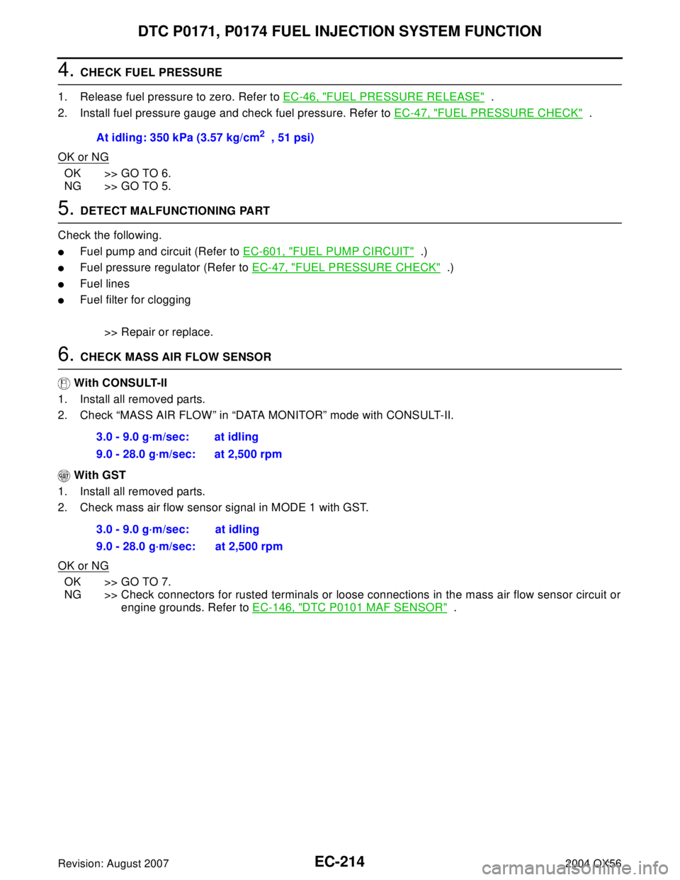
4. CHECK FUEL PRESSURE
1. Release fuel pressure to zero. Refer to EC-46, "
FUEL PRESSURE RELEASE" .
2. Install fuel pressure gauge and check fuel pressure. Refer to EC-47, "
FUEL PRESSURE CHECK" .
OK or NG
OK >> GO TO 6.
NG >> GO TO 5.
5. DETECT MALFUNCTIONING PART
Check the following.
�Fuel pump and circuit (Refer to EC-601, "FUEL PUMP CIRCUIT" .)
�Fuel pressure regulator (Refer to EC-47, "FUEL PRESSURE CHECK" .)
�Fuel lines
�Fuel filter for clogging
>> Repair or replace.
6. CHECK MASS AIR FLOW SENSOR
With CONSULT-II
1. Install all removed parts.
2. Check “MASS AIR FLOW” in “DATA MONITOR” mode with CONSULT-II.
With GST
1. Install all removed parts.
2. Check mass air flow sensor signal in MODE 1 with GST.
OK or NG
OK >> GO TO 7.
NG >> Check connectors for rusted terminals or loose connections in the mass air flow sensor circuit or
engine grounds. Refer to EC-146, "
DTC P0101 MAF SENSOR" . At idling: 350 kPa (3.57 kg/cm
2 , 51 psi)
3.0 - 9.0 g·m/sec: at idling
9.0 - 28.0 g·m/sec: at 2,500 rpm
3.0 - 9.0 g·m/sec: at idling
9.0 - 28.0 g·m/sec: at 2,500 rpm
Page 1414 of 3371

DTC P0172, P0175 FUEL INJECTION SYSTEM FUNCTION
EC-223
C
D
E
F
G
H
I
J
K
L
MA
EC
Revision: August 20072004 QX56
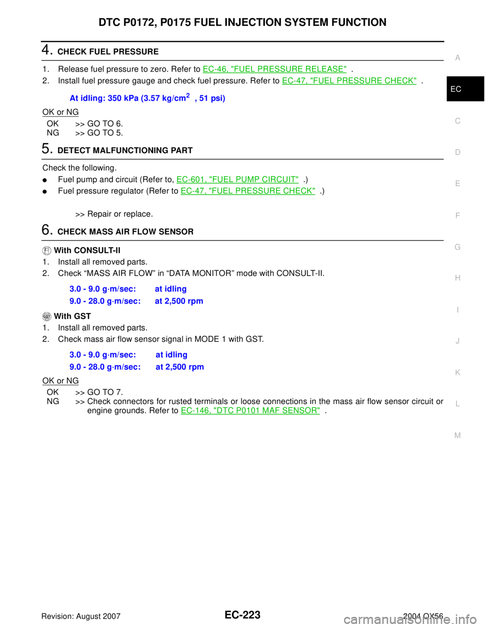
4. CHECK FUEL PRESSURE
1. Release fuel pressure to zero. Refer to EC-46, "
FUEL PRESSURE RELEASE" .
2. Install fuel pressure gauge and check fuel pressure. Refer to EC-47, "
FUEL PRESSURE CHECK" .
OK or NG
OK >> GO TO 6.
NG >> GO TO 5.
5. DETECT MALFUNCTIONING PART
Check the following.
�Fuel pump and circuit (Refer to, EC-601, "FUEL PUMP CIRCUIT" .)
�Fuel pressure regulator (Refer to EC-47, "FUEL PRESSURE CHECK" .)
>> Repair or replace.
6. CHECK MASS AIR FLOW SENSOR
With CONSULT-II
1. Install all removed parts.
2. Check “MASS AIR FLOW” in “DATA MONITOR” mode with CONSULT-II.
With GST
1. Install all removed parts.
2. Check mass air flow sensor signal in MODE 1 with GST.
OK or NG
OK >> GO TO 7.
NG >> Check connectors for rusted terminals or loose connections in the mass air flow sensor circuit or
engine grounds. Refer to EC-146, "
DTC P0101 MAF SENSOR" . At idling: 350 kPa (3.57 kg/cm
2 , 51 psi)
3.0 - 9.0 g·m/sec: at idling
9.0 - 28.0 g·m/sec: at 2,500 rpm
3.0 - 9.0 g·m/sec: at idling
9.0 - 28.0 g·m/sec: at 2,500 rpm
Page 1419 of 3371
EC-228Revision: August 2007
DTC P0181 FTT SENSOR
2004 QX56
Diagnostic ProcedureUBS00H38
1. CHECK DTC WITH COMBINATION METER
Refer to DI-5, "
COMBINATION METERS" .
OK or NG
OK >> GO TO 2.
NG >> Go to DI-22, "
Fuel Level Sensor Unit Inspection" .
2. CHECK GROUND CONNECTIONS
1. Turn ignition switch OFF.
2. Loosen and retighten three ground screws on the body.
Refer to EC-133, "
Ground Inspection" .
OK or NG
OK >> GO TO 3.
NG >> Repair or replace ground connections.
3. CHECK FUEL TANK TEMPERATURE SENSOR POWER SUPPLY CIRCUIT
1. Disconnect “fuel level sensor unit and fuel pump” harness con-
nector.
2. Turn ignition switch ON.
3. Check voltage between “fuel level sensor unit and fuel pump”
terminal 4 and ground with CONSULT-II or tester.
OK or NG
OK >> GO TO 5.
NG >> GO TO 4.
BBIA0354E
BBIA0583E
Voltage: Approximately 5V
PBIB0932E
Page 1420 of 3371

DTC P0181 FTT SENSOR
EC-229
C
D
E
F
G
H
I
J
K
L
MA
EC
Revision: August 20072004 QX56
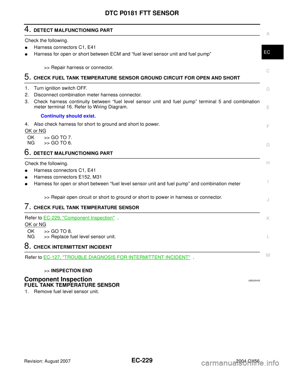
4. DETECT MALFUNCTIONING PART
Check the following.
�Harness connectors C1, E41
�Harness for open or short between ECM and “fuel level sensor unit and fuel pump”
>> Repair harness or connector.
5. CHECK FUEL TANK TEMPERATURE SENSOR GROUND CIRCUIT FOR OPEN AND SHORT
1. Turn ignition switch OFF.
2. Disconnect combination meter harness connector.
3. Check harness continuity between “fuel level sensor unit and fuel pump” terminal 5 and combination
meter terminal 16. Refer to Wiring Diagram.
4. Also check harness for short to ground and short to power.
OK or NG
OK >> GO TO 7.
NG >> GO TO 6.
6. DETECT MALFUNCTIONING PART
Check the following.
�Harness connectors C1, E41
�Harness connectors E152, M31
�Harness for open or short between “fuel level sensor unit and fuel pump” and combination meter
>> Repair open circuit or short to ground or short to power in harness or connector.
7. CHECK FUEL TANK TEMPERATURE SENSOR
Refer to EC-229, "
Component Inspection" .
OK or NG
OK >> GO TO 8.
NG >> Replace fuel level sensor unit.
8. CHECK INTERMITTENT INCIDENT
Refer to EC-127, "
TROUBLE DIAGNOSIS FOR INTERMITTENT INCIDENT" .
>>INSPECTION END
Component InspectionUBS00H39
FUEL TANK TEMPERATURE SENSOR
1. Remove fuel level sensor unit.Continuity should exist.
Page 1421 of 3371
EC-230Revision: August 2007
DTC P0181 FTT SENSOR
2004 QX56
2. Check resistance between “fuel level sensor unit and fuel pump”
terminals 4 and 5 by heating with hot water or heat gun as
shown in the figure.
Removal and InstallationUBS00H3A
FUEL TANK TEMPERATURE SENSOR
Refer to FL-5, "FUEL LEVEL SENSOR UNIT, FUEL FILTER AND FUEL PUMP ASSEMBLY" .
Temperature °C (°F) Resistance kΩ
20 (68) 2.3 - 2.7
50 (122) 0.79 - 0.90
PBIB0931E
Page 1424 of 3371
DTC P0182, P0183 FTT SENSOR
EC-233
C
D
E
F
G
H
I
J
K
L
MA
EC
Revision: August 20072004 QX56
Diagnostic ProcedureUBS00H3F
1. CHECK DTC WITH COMBINATION METER
Refer to DI-5, "
COMBINATION METERS" .
OK or NG
OK >> GO TO 2.
NG >> Go to DI-22, "
Fuel Level Sensor Unit Inspection" .
2. CHECK GROUND CONNECTIONS
1. Turn ignition switch OFF.
2. Loosen and retighten three ground screws on the body.
Refer to EC-133, "
Ground Inspection" .
OK or NG
OK >> GO TO 3.
NG >> Repair or replace ground connections.
3. CHECK FUEL TANK TEMPERATURE SENSOR POWER SUPPLY CIRCUIT
1. Disconnect “fuel level sensor unit and fuel pump” harness con-
nector.
2. Turn ignition switch ON.
3. Check voltage between “fuel level sensor unit and fuel pump”
terminal 4 and ground with CONSULT-II or tester.
OK or NG
OK >> GO TO 5.
NG >> GO TO 4.
BBIA0354E
BBIA0583E
Voltage: Approximately 5V
PBIB0932E