Page 3104 of 3371

TROUBLE DIAGNOSIS
SRS-43
C
D
E
F
G
I
J
K
L
MA
B
SRS
Revision: August 20072004 QX56
Trouble Diagnosis: “AIR BAG” Warning Lamp Does Not Turn OffEHS000WJ
DIAGNOSTIC PROCEDURE 6
1. CHECK CONDITION OF AIR BAG MODULE
Inspect for deployed air bag modules or seat belt pre-tensioners.
Are air bag modules or seat belt pre-tensioners deployed?
Yes >> Refer to SRS-60, "COLLISION DIAGNOSIS" .
No >> GO TO 2.
2. CHECK THE AIR BAG FUSE
Check 10A fuse [No. 13, located in the fuse block (J/B)].
Refer to PG-4, "
POWER SUPPLY ROUTING CIRCUIT" .
OK or NG
OK >> GO TO 4.
NG >> GO TO 3.
3. CHECK AIR BAG FUSE AGAIN
Replace 10A fuse [No. 13, located in the fuse block (J/B)] and turn ignition switch ON.
Does the fuse blow again?
Yes >> Repair harness.
No >> Inspection End.
4. CHECK AIR BAG DIAGNOSIS SENSOR UNIT
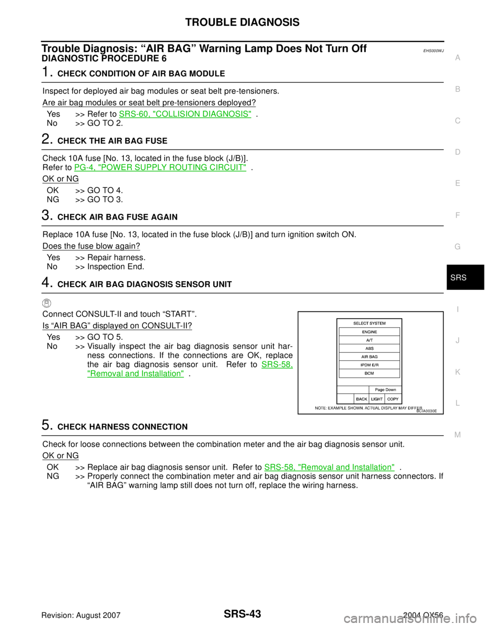
Connect CONSULT-II and touch “START”.
Is
“AIR BAG” displayed on CONSULT-II?
Yes >> GO TO 5.
No >> Visually inspect the air bag diagnosis sensor unit har-
ness connections. If the connections are OK, replace
the air bag diagnosis sensor unit. Refer to SRS-58,
"Removal and Installation" .
5. CHECK HARNESS CONNECTION
Check for loose connections between the combination meter and the air bag diagnosis sensor unit.
OK or NG
OK >> Replace air bag diagnosis sensor unit. Refer to SRS-58, "Removal and Installation" .
NG >> Properly connect the combination meter and air bag diagnosis sensor unit harness connectors. If
“AIR BAG” warning lamp still does not turn off, replace the wiring harness.
BCIA0030E
Page 3105 of 3371
SRS-44
TROUBLE DIAGNOSIS
Revision: August 20072004 QX56
Trouble Diagnosis: “AIR BAG” Warning Lamp Does Not Turn OnEHS000WK
DIAGNOSTIC PROCEDURE 7
1. CHECK METER FUSE
Check the 10A fuse [No. 14, located in the fuse block (J/B)].
Refer to PG-4, "
POWER SUPPLY ROUTING CIRCUIT" .
OK or NG
OK >> GO TO 3.
NG >> GO TO 2.
2. CHECK METER FUSE AGAIN
Replace 10A fuse [No. 14, located in the fuse block (J/B)] and turn ignition switch ON.
Does the fuse blow again?
Yes >> Repair harness.
No >> Inspection End.
3. CHECK HARNESS CONNECTION BETWEEN DIAGNOSIS SENSOR UNIT AND COMBINATION
METER
Disconnect the air bag diagnosis sensor unit harness connectors and turn ignition switch ON.
Does
“AIR BAG” warning lamp turn on?
Yes >> Replace the air bag diagnosis sensor unit. Refer to SRS-58, "Removal and Installation" .
No >> Check the combination meter ground circuits.
Page 3138 of 3371

ALL-MODE 4WD SYSTEM
TF-13
C
E
F
G
H
I
J
K
L
MA
B
TF
Revision: August 20072004 QX56
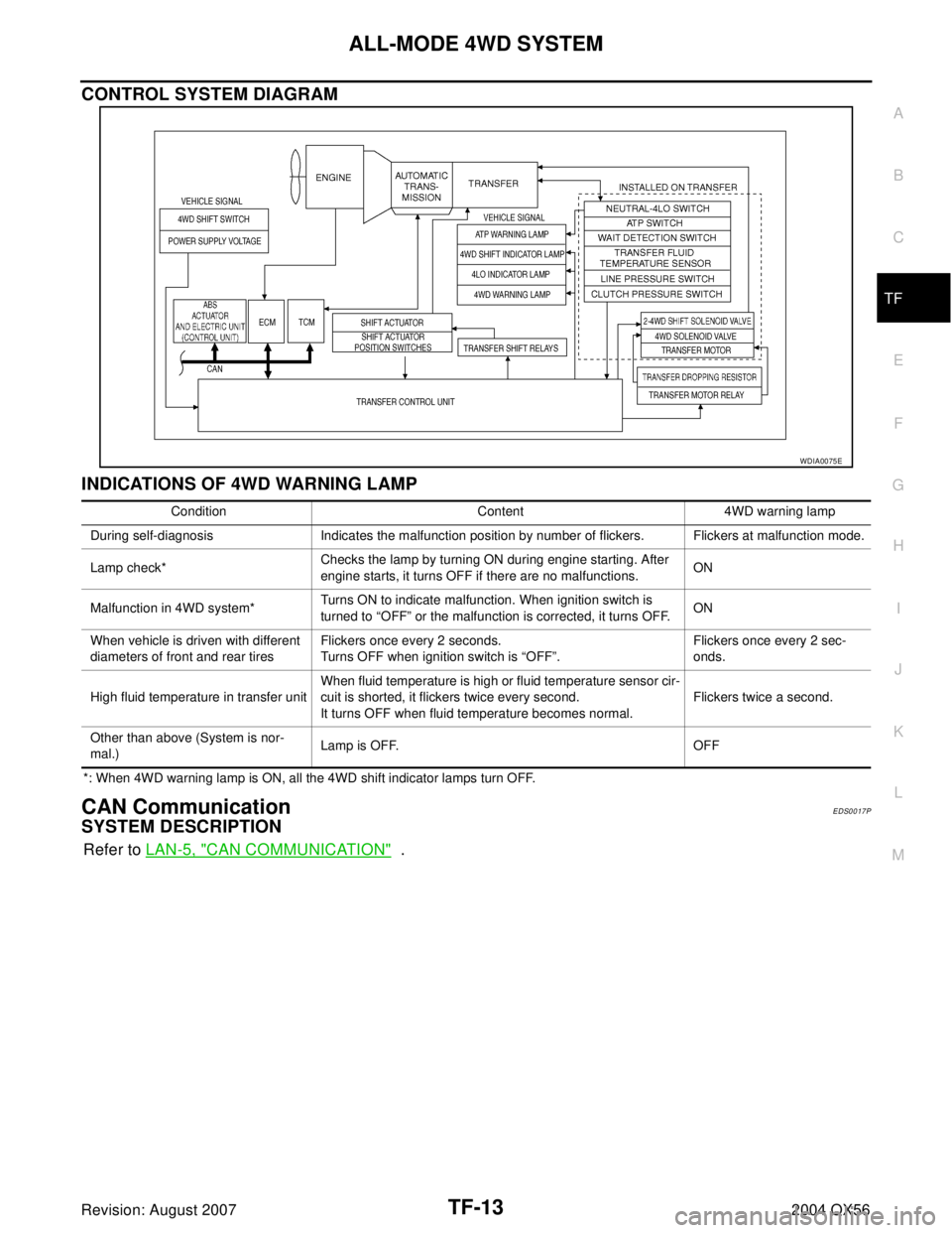
CONTROL SYSTEM DIAGRAM
INDICATIONS OF 4WD WARNING LAMP
*: When 4WD warning lamp is ON, all the 4WD shift indicator lamps turn OFF.
CAN CommunicationEDS0017P
SYSTEM DESCRIPTION
Refer to LAN-5, "CAN COMMUNICATION" .
WDIA0075E
Condition Content 4WD warning lamp
During self-diagnosis Indicates the malfunction position by number of flickers. Flickers at malfunction mode.
Lamp check*Checks the lamp by turning ON during engine starting. After
engine starts, it turns OFF if there are no malfunctions.ON
Malfunction in 4WD system*Turns ON to indicate malfunction. When ignition switch is
turned to “OFF” or the malfunction is corrected, it turns OFF.ON
When vehicle is driven with different
diameters of front and rear tiresFlickers once every 2 seconds.
Turns OFF when ignition switch is “OFF”.Flickers once every 2 sec-
onds.
High fluid temperature in transfer unitWhen fluid temperature is high or fluid temperature sensor cir-
cuit is shorted, it flickers twice every second.
It turns OFF when fluid temperature becomes normal.Flickers twice a second.
Other than above (System is nor-
mal.)Lamp is OFF. OFF
Page 3152 of 3371
ON BOARD DIAGNOSTIC SYSTEM DESCRIPTION
TF-27
C
E
F
G
H
I
J
K
L
MA
B
TF
Revision: August 20072004 QX56
ON BOARD DIAGNOSTIC SYSTEM DESCRIPTIONPFP:00000
Trouble Diagnosis without CONSULT-IIEDS0017U
DESCRIPTION
If the engine starts when there is something wrong with the all-mode 4WD system, the 4WD warning lamp
turns ON or flickers in the combination meter. When the system functions properly, the warning lamp turns ON
when the ignition switch is turned to ON, and it turns OFF after engine starts.
To locate the cause of a problem, start the self-diagnosis function. The 4WD warning lamp in the combination
meter will indicate the problem area by flickering according to the self-diagnostic results. As for the details of
the 4WD warning lamp flickering patterns, refer to TF-28
.
Page 3212 of 3371

TROUBLE DIAGNOSES FOR SYMPTOMS
TF-87
C
E
F
G
H
I
J
K
L
MA
B
TF
Revision: August 20072004 QX56
Symptom 2. 4WD Warning Lamp Does Not Turn ON (Although the ignition
switch is turned ON, the 4WD warning lamp does not turn ON)
EDS0018F
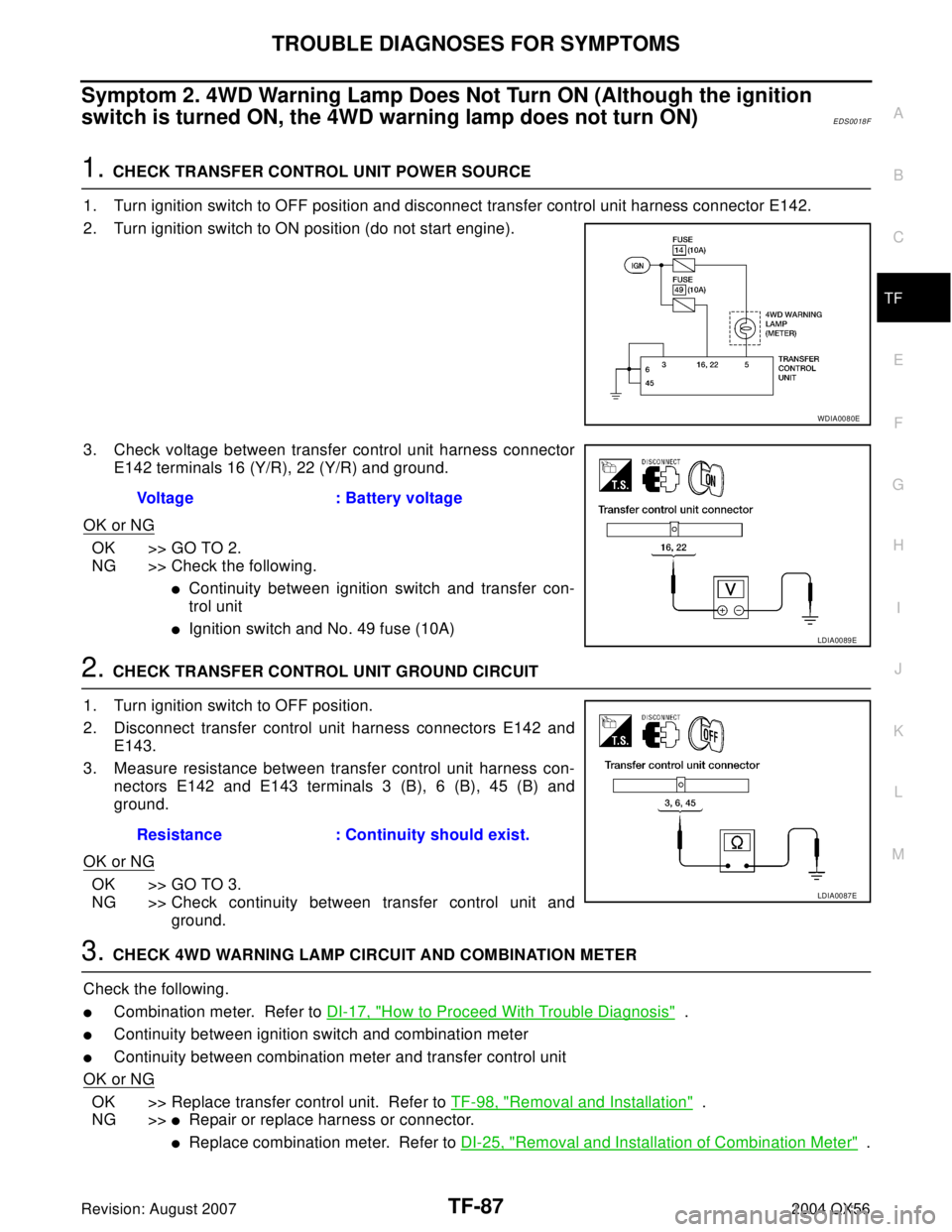
1. CHECK TRANSFER CONTROL UNIT POWER SOURCE
1. Turn ignition switch to OFF position and disconnect transfer control unit harness connector E142.
2. Turn ignition switch to ON position (do not start engine).
3. Check voltage between transfer control unit harness connector
E142 terminals 16 (Y/R), 22 (Y/R) and ground.
OK or NG
OK >> GO TO 2.
NG >> Check the following.
�Continuity between ignition switch and transfer con-
trol unit
�Ignition switch and No. 49 fuse (10A)
2. CHECK TRANSFER CONTROL UNIT GROUND CIRCUIT
1. Turn ignition switch to OFF position.
2. Disconnect transfer control unit harness connectors E142 and
E143.
3. Measure resistance between transfer control unit harness con-
nectors E142 and E143 terminals 3 (B), 6 (B), 45 (B) and
ground.
OK or NG
OK >> GO TO 3.
NG >> Check continuity between transfer control unit and
ground.
3. CHECK 4WD WARNING LAMP CIRCUIT AND COMBINATION METER
Check the following.
�Combination meter. Refer to DI-17, "How to Proceed With Trouble Diagnosis" .
�Continuity between ignition switch and combination meter
�Continuity between combination meter and transfer control unit
OK or NG
OK >> Replace transfer control unit. Refer to TF-98, "Removal and Installation" .
NG >>
�Repair or replace harness or connector.
�Replace combination meter. Refer to DI-25, "Removal and Installation of Combination Meter" .
WDIA0080E
Voltage : Battery voltage
LDIA0089E
Resistance : Continuity should exist.
LDIA0087E
Page 3214 of 3371
TROUBLE DIAGNOSES FOR SYMPTOMS
TF-89
C
E
F
G
H
I
J
K
L
MA
B
TF
Revision: August 20072004 QX56
Symptom 4. ATP Warning Lamp Does Not Turn ON (When 4WD shift switch is
set from 4H to 4LO with the A/T selector lever in P position, the ATP warning
lamp does not turn on)
EDS0018H
1. CHECK ATP SWITCH CIRCUIT
Check ATP switch circuit.
Refer to TF-69, "
ATP SWITCH, WAIT DETECTION SWITCH AND
NEUTRAL-4LO SWITCH" .
OK or NG
OK >> GO TO 2.
NG >> Check, repair or replace faulty parts.
2. CHECK COMBINATION METER
Check the combination meter. Refer to DI-17, "
How to Proceed With Trouble Diagnosis"
OK or NG
OK >> Replace transfer control unit. Refer to TF-98, "Removal and Installation" .
NG >> Replace combination meter. Refer to DI-25, "
Removal and Installation of Combination Meter" .
WDIA0103E
Page 3216 of 3371

TROUBLE DIAGNOSES FOR SYMPTOMS
TF-91
C
E
F
G
H
I
J
K
L
MA
B
TF
Revision: August 20072004 QX56
3. CHECK 4LO INDICATOR LAMP CIRCUIT AND COMBINATION METER
Check the following.
�Combination meter. Refer to DI-17, "How to Proceed With Trouble Diagnosis" .
�Continuity between ignition switch and combination meter
�Continuity between combination meter and transfer control unit
�Condition of ATP and neutral-4LO switch circuit. Refer to TF-69, "ATP SWITCH, WAIT DETECTION
SWITCH AND NEUTRAL-4LO SWITCH" .
OK or NG
OK >> Replace transfer control unit. Refer to TF-98, "Removal and Installation" .
NG >>
�Repair or replace harness or connector.
�Replace combination meter. Refer to DI-25, "Removal and Installation of Combination Meter" .
�Replace ATP or neutral-4LO switch.
Symptom 6. 4WD Shift Indicator Lamp Does Not Indicate “LOCK” (When 4WD
shift switch is set to “4H”, 4WD shift indicator lamp does not indicate “LOCK”)
EDS0018J
1. CHECK 4WD WARNING LAMP
Is 4WD warning lamp turned ON?
Ye s o r N o
Yes >> Refer to TF-27, "Trouble Diagnosis without CONSULT-
II" .
No >> GO TO 2.
2. CHECK NEUTRAL-4LO, WAIT DETECTION AND ATP SWITCH CIRCUITS
Check neutral-4LO, wait detection and ATP switch circuits. Refer to TF-69, "
ATP SWITCH, WAIT DETECTION
SWITCH AND NEUTRAL-4LO SWITCH" .
OK or NG
OK >> GO TO 3.
NG >> Check, repair or replace faulty parts.
3. CHECK PROCEDURES FROM THE BEGINNING AGAIN
Check again.
OK or NG
OK >> Inspection End.
NG >> Recheck each connector pin terminals for damage or loose connection.
WDIA0071E
Page 3245 of 3371
TF-120
CENTER CASE
Revision: August 20072004 QX56
3. Remove control valve assembly bolts.
4. Remove snap ring. Then push connector assembly into center
case to remove control valve assembly.
5. Remove lip seals from center case.
CAUTION:
There are two kinds of lip seals (lip seal of large inner diam-
eter: 5 pieces, lip seal of small inner diameter: 2 pieces).
Confirm the position before disassembly.
6. Remove all bolts except for the two as shown.
7. Remove 4WD solenoid valve, clutch pressure switch, 2-4WD
shift solenoid valve, line pressure switch, and transfer fluid tem-
perature sensor from control valve assembly.
SDIA2121E
SDIA2122E
SDIA2123E
SDIA2124E
PDIA0183E