Page 2843 of 3371
RFD-12
REAR FINAL DRIVE ASSEMBLY
Revision: August 20072004 QX56
CAUTION:
Final drive pinion nut torque will be determined when adjusting the total preload. Refer to RFD-12,
"TOTAL PRELOAD" .
Pre-InspectionEDS002JO
Before disassembling the rear final drive, perform the following inspections.
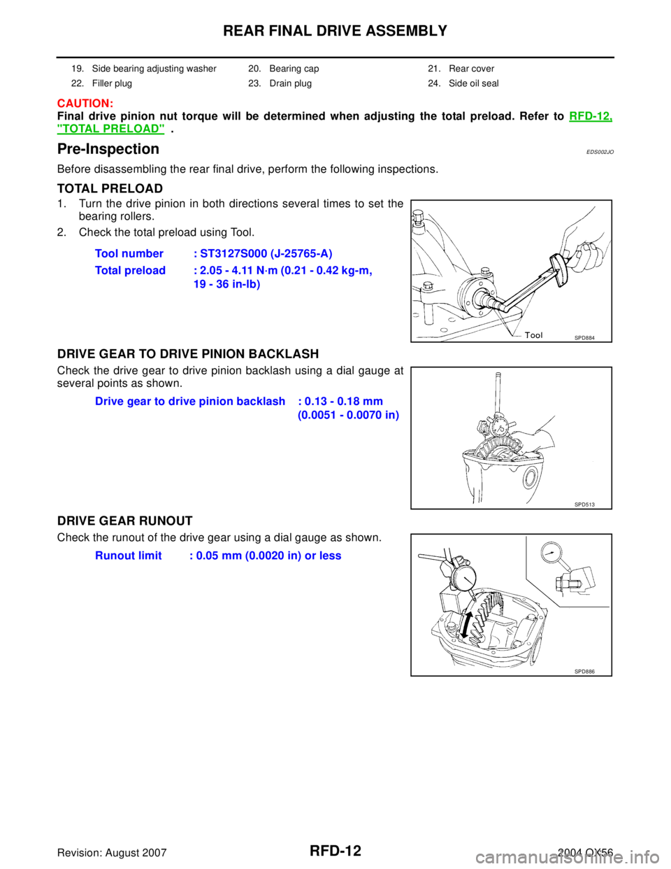
TOTAL PRELOAD
1. Turn the drive pinion in both directions several times to set the
bearing rollers.
2. Check the total preload using Tool.
DRIVE GEAR TO DRIVE PINION BACKLASH
Check the drive gear to drive pinion backlash using a dial gauge at
several points as shown.
DRIVE GEAR RUNOUT
Check the runout of the drive gear using a dial gauge as shown.
19. Side bearing adjusting washer 20. Bearing cap 21. Rear cover
22. Filler plug 23. Drain plug 24. Side oil seal
Tool number : ST3127S000 (J-25765-A)
Total preload : 2.05 - 4.11 N·m (0.21 - 0.42 kg-m,
19 - 36 in-lb)
SPD8 84
Drive gear to drive pinion backlash : 0.13 - 0.18 mm
(0.0051 - 0.0070 in)
SPD5 13
Runout limit : 0.05 mm (0.0020 in) or less
SPD8 86
Page 2855 of 3371

RFD-24
REAR FINAL DRIVE ASSEMBLY
Revision: August 20072004 QX56
6. Measure the drive gear-to-drive pinion backlash with a dial indi-
cator at several points.
�If the backlash is less than specification, adjust the washer thickness. Decrease the thickness of the left
washer and increase the thickness of the right washer by the same amount.
�If the backlash is greater than specification, adjust the washer thickness. Increase the thickness of the
left washer and decrease the thickness of the right washer by the same amount.
�Never change the total amount of the washers as it will change the bearing preload.
7. Check the total preload using Tool.
When checking the preload, turn the drive pinion in both direc-
tions several times to seat the bearing rollers correctly.
�If the preload is greater than specification, remove the same amount of washer thickness from each
side.
�If the preload is less than specification, add the same amount of washer thickness to each side.
�Never add or remove a different amount of washer thickness from each side. A difference in the amount
of washer thickness will change the drive gear-to-drive pinion backlash.
8. Recheck the drive gear-to-drive pinion backlash. Increase or decrease in thickness of the washers will
change the drive gear-to-drive pinion backlash.
�Check whether the backlash varies excessively in different places. Foreign matter may be caught
between the drive gear and the differential case causing the variation in backlash.
�The backlash can vary greatly even when the drive gear runout is within specification. To correct this
variation, replace the hypoid gear set or differential case.
9. Check runout of drive gear using a dial indicator.
10. Check the tooth contact.
Refer to RFD-19, "
TOOTH CONTACT" . Drive gear to drive pinion backlash : 0.13 - 0.18 mm
(0.0051 - 0.0070 in)
SPD5 13
Tool number : ST3127S000 (J-25765-A)
SPD8 84
Total preload : 2.05 - 4.11 N·m (0.21 - 0.42 kg-m, 19 - 36 in-lb)
Runout limit : 0.05 mm (0.0020 in) or less
SPD5 24
Page 2858 of 3371
SERVICE DATA AND SPECIFICATIONS (SDS)
RFD-27
C
E
F
G
H
I
J
K
L
MA
B
RFD
Revision: August 20072004 QX56
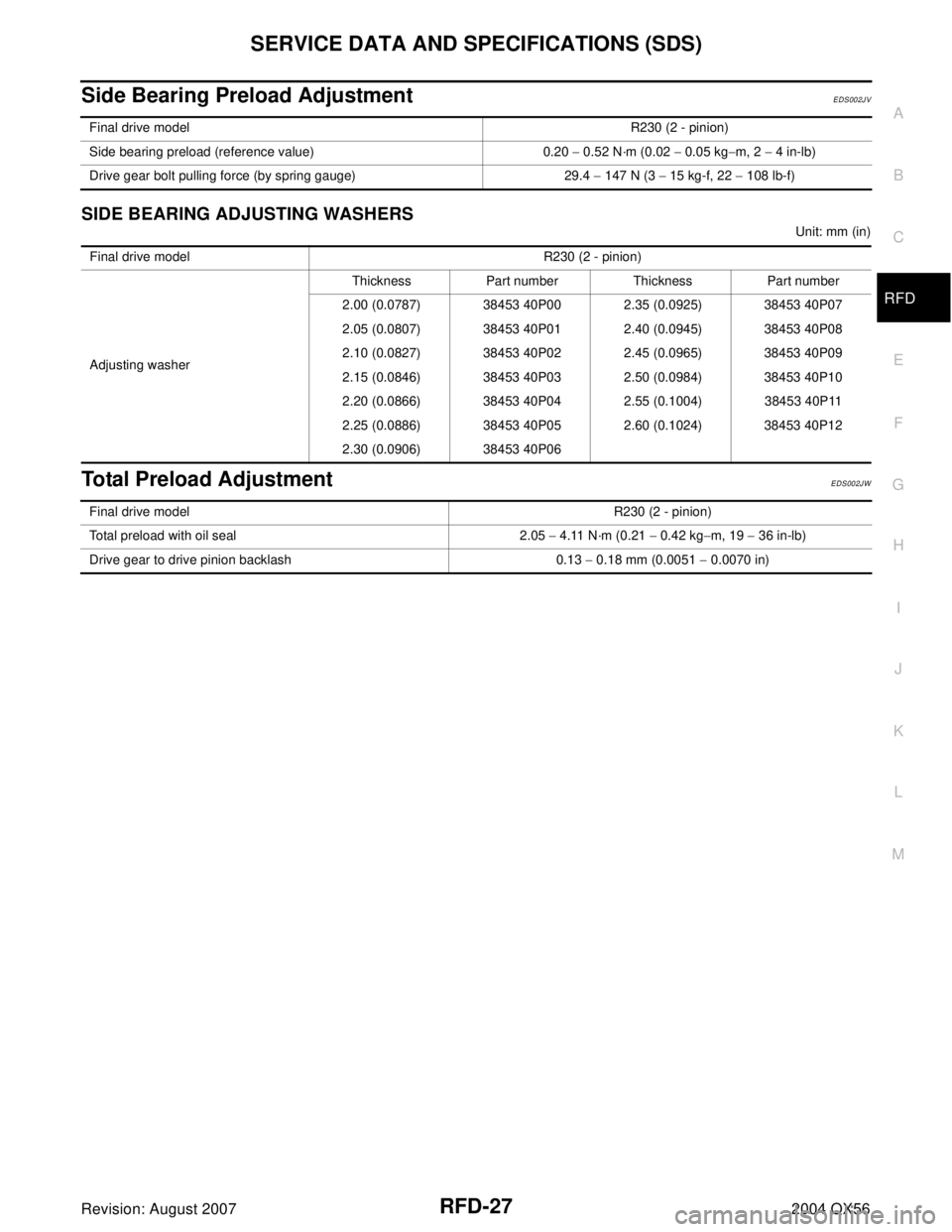
Side Bearing Preload Adjustment EDS002JV
SIDE BEARING ADJUSTING WASHERS
Unit: mm (in)
Total Preload AdjustmentEDS002JW
Final drive modelR230 (2 - pinion)
Side bearing preload (reference value) 0.20 − 0.52 N·m (0.02 − 0.05 kg−m, 2 − 4 in-lb)
Drive gear bolt pulling force (by spring gauge) 29.4 − 147 N (3 − 15 kg-f, 22 − 108 lb-f)
Final drive model R230 (2 - pinion)
Adjusting washerThickness Part number Thickness Part number
2.00 (0.0787) 38453 40P00 2.35 (0.0925) 38453 40P07
2.05 (0.0807) 38453 40P01 2.40 (0.0945) 38453 40P08
2.10 (0.0827) 38453 40P02 2.45 (0.0965) 38453 40P09
2.15 (0.0846) 38453 40P03 2.50 (0.0984) 38453 40P10
2.20 (0.0866) 38453 40P04 2.55 (0.1004) 38453 40P11
2.25 (0.0886) 38453 40P05 2.60 (0.1024) 38453 40P12
2.30 (0.0906) 38453 40P06
Final drive modelR230 (2 - pinion)
Total preload with oil seal 2.05 − 4.11 N·m (0.21 − 0.42 kg−m, 19 − 36 in-lb)
Drive gear to drive pinion backlash 0.13 − 0.18 mm (0.0051 − 0.0070 in)
Page 2885 of 3371
RSU-26
REAR SUSPENSION ASSEMBLY
Revision: August 20072004 QX56
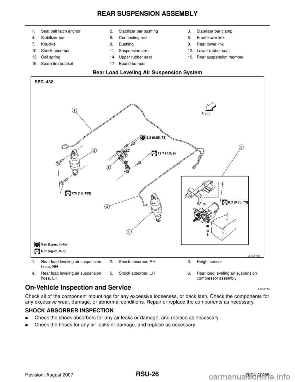
Rear Load Leveling Air Suspension System
On-Vehicle Inspection and ServiceEES0011G
Check all of the component mountings for any excessive looseness, or back lash. Check the components for
any excessive wear, damage, or abnormal conditions. Repair or replace the components as necessary.
SHOCK ABSORBER INSPECTION
�Check the shock absorbers for any air leaks or damage, and replace as necessary.
�Check the hoses for any air leaks or damage, and replace as necessary.
1. Seat belt latch anchor 2. Stabilizer bar bushing 3. Stabilizer bar clamp
4. Stabilizer bar 5. Connecting rod 6. Front lower link
7. Knuckle 8. Bushing 9. Rear lower link
10. Shock absorber 11. Suspension arm 12. Lower rubber seat
13. Coil spring 14. Upper rubber seat 15. Rear suspension member
16. Spare tire bracket 17. Bound bumper
LEIA0072E
1. Rear load leveling air suspension
hose, RH2. Shock absorber, RH 3. Height sensor
4. Rear load leveling air suspension
hose, LH5. Shock absorber, LH 6. Rear load leveling air suspension
compressor assembly
Page 2888 of 3371
REAR SUSPENSION ASSEMBLY
RSU-29
C
D
F
G
H
I
J
K
L
MA
B
RSU
Revision: August 20072004 QX56
5. Push the vehicle slowly ahead to rotate the wheels 180°
degrees (a half turn).
If the wheels are rotated more than 180° degrees (a half turn),
then repeat the above steps. Never push the vehicle backward.
6. Measure the distance “B” (front side) across from tire to tire.
7. If the toe-in is outside the specified value, adjust the toe-in using
the adjusting bolt in the rear lower link.
CAUTION:
Be sure to adjust equally on RH and LH sides using the
adjusting bolt.
NOTE:
Toe changes about 1.5 mm (0.059 in) [one side] with each grad-
uation of the adjusting bolt.
8. Tighten the adjusting bolt nuts to specification.Total toe-in : Refer to RSU-47, "
Wheel Alignment" .
SFA234AC
LEIA0009E
Page 2905 of 3371
RSU-46
CONTROL UNIT
Revision: August 20072004 QX56
CONTROL UNITPFP:47850
Removal and InstallationEES0011V
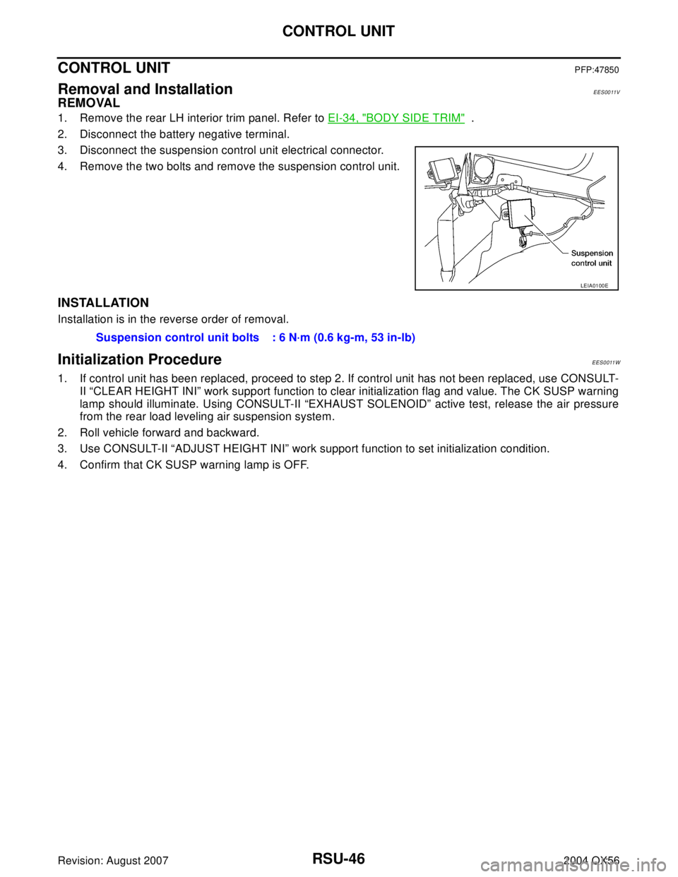
REMOVAL
1. Remove the rear LH interior trim panel. Refer to EI-34, "BODY SIDE TRIM" .
2. Disconnect the battery negative terminal.
3. Disconnect the suspension control unit electrical connector.
4. Remove the two bolts and remove the suspension control unit.
INSTALLATION
Installation is in the reverse order of removal.
Initialization ProcedureEES0011W
1. If control unit has been replaced, proceed to step 2. If control unit has not been replaced, use CONSULT-
II “CLEAR HEIGHT INI” work support function to clear initialization flag and value. The CK SUSP warning
lamp should illuminate. Using CONSULT-II “EXHAUST SOLENOID” active test, release the air pressure
from the rear load leveling air suspension system.
2. Roll vehicle forward and backward.
3. Use CONSULT-II “ADJUST HEIGHT INI” work support function to set initialization condition.
4. Confirm that CK SUSP warning lamp is OFF.
LEIA0100E
Suspension control unit bolts : 6 N·m (0.6 kg-m, 53 in-lb)
Page 2914 of 3371
SEAT BELTS
SB-7
C
D
E
F
G
I
J
K
L
MA
B
SB
Revision: August 20072004 QX56
4. Remove the seat belt guide bolt.
5. Remove seat belt retractor anchor bolt and the seat belt retractor and belt assembly.
6. Remove the seat belt height adjustor assembly.
INSTALLATION
Installation is in the reverse order of removal.
�Ensure that seat belt height adjuster is locked in the lowest position during installation.
REMOVAL OF SEAT BELT BUCKLE
1. Remove the rear bucket seat. Refer to SE-103, "Removal and
Installation" .
2. Remove the screw and seat cushion finisher. Refer to SE-103,
"Removal and Installation" .
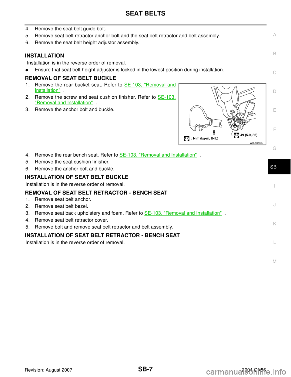
3. Remove the anchor bolt and buckle.
4. Remove the rear bench seat. Refer to SE-103, "
Removal and Installation" .
5. Remove the seat cushion finisher.
6. Remove the anchor bolt and buckle.
INSTALLATION OF SEAT BELT BUCKLE
Installation is in the reverse order of removal.
REMOVAL OF SEAT BELT RETRACTOR - BENCH SEAT
1. Remove seat belt anchor.
2. Remove seat belt bezel.
3. Remove seat back upholstery and foam. Refer to SE-103, "
Removal and Installation" .
4. Remove seat belt retractor cover.
5. Remove bolt and remove seat belt retractor and belt assembly.
INSTALLATION OF SEAT BELT RETRACTOR - BENCH SEAT
Installation is in the reverse order of removal.
WHIA0229E
Page 2918 of 3371
SEAT BELTS
SB-11
C
D
E
F
G
I
J
K
L
MA
B
SB
Revision: August 20072004 QX56
SEAT BELT RETRACTOR ON-VEHICLE CHECK
Emergency Locking Retractors (ELR) and Automatic Locking Retractors (ALR)
NOTE:
All seat belt retractors are of the Emergency Locking Retractors (ELR) type. In an emergency (sudden stop)
the retractor will lock and prevent the belt from extending any further. All 3-point type seat belt retractors
except the driver's seat belt also have an Automatic Locking Retractors (ALR) mode. The ALR mode (also
called child restraint mode) is used when installing child seats. The ALR mode is activated when the seat belt
is fully extended. When the belt is then retracted partially, the ALR mode automatically locks the seat belt in a
specific position so the belt cannot be extended any further. To cancel the ALR mode, allow the seat belt to
fully wind back into the retractor.
Check the seat belt retractors using the following test(s) to determine if a seat belt retractor and belt assembly
is operating properly.
ELR Function Stationary Check
Grasp the shoulder belt and pull forward quickly. The retractor should lock and prevent the belt from extending
further.
ALR Function Stationary Check
1. Pull out entire length of seat belt from retractor until a click is heard.
2. Retract the belt partially. A clicking noise should be heard as the belt retracts indicating that the retractor is
in the Automatic Locking Retractor (ALR) mode.
3. Grasp the seat belt and try to pull out the retractor. The belt must lock and not extend any further. If neces-
sary replace the seat belt retractor and belt assembly.
4. Allow the entire length of the belt to retract to cancel the automatic locking mode.
ELR Function Moving Check
WA RN ING:
Perform the following test in a safe, open area clear of other vehicles and obstructions (for example, a
large, empty parking lot). Road surface must be paved and dry. DO NOT perform the following test on
wet or gravel roads or on public streets and highways. This could result in an accident and serious
personal injury. The driver and passenger must be prepared to brace themselves in the event the
retractor does not lock.
1. Fasten drivers seat belt. Buckle a passenger into the seat for the belt that is to be tested.
2. Proceed to the designated safe area.
3. Drive the vehicle at approximately 16 km/h (10 MPH). Notify any passengers of a pending sudden stop.
The driver and passenger must be prepared to brace themselves in the event the retractor does not lock.
Apply brakes firmly and make a very hard stop.
During stop, seat belts should lock and not be extended. If the seat belt retractor and belt assembly does not
lock, perform the retractor off-vehicle check.
SEAT BELT RETRACTOR OFF-VEHICLE CHECK
1. Remove the seat belt retractor and belt assembly.
2. Slowly pull out belt while tilting the retractor assembly forward from the mounted position without twisting
the retractor assembly as shown in the illustration.