Page 2661 of 3371

PG-2Revision: August 20072004 QX56 SRS COMPONENT TYPE) ................................. 70
ELECTRICAL UNITS ................................................ 71
Terminal Arrangement ............................................ 71
STANDARDIZED RELAY .......................................... 72
Description .............................................................. 72
NORMAL OPEN, NORMAL CLOSED AND
MIXED TYPE RELAYS ........................................ 72
TYPE OF STANDARDIZED RELAYS .................. 72SUPER MULTIPLE JUNCTION (SMJ) ......................74
Terminal Arrangement .............................................74
FUSE BLOCK-JUNCTION BOX(J/B) .......................76
Terminal Arrangement .............................................76
FUSE AND FUSIBLE LINK BOX ..............................77
Terminal Arrangement .............................................77
FUSE AND RELAY BOX ...........................................78
Terminal Arrangement .............................................78
Page 2676 of 3371

IPDM E/R (INTELLIGENT POWER DISTRIBUTION MODULE ENGINE ROOM)
PG-17
C
D
E
F
G
H
I
J
L
MA
B
PG
Revision: August 20072004 QX56
IPDM E/R (INTELLIGENT POWER DISTRIBUTION MODULE ENGINE ROOM)
PFP:284B7
System DescriptionEKS007NN
�IPDM E/R (Intelligent Power Distribution Module Engine Room) integrates the relay box and fuse block
which were originally placed in engine compartment. It controls integrated relays via IPDM E/R control cir-
cuits.
�IPDM E/R-integrated control circuits perform ON-OFF operation of relays, CAN communication control,
etc.
�It controls operation of each electrical component via ECM, BCM and CAN communication lines.
CAUTION:
None of the IPDM E/R integrated relays can be removed.
SYSTEMS CONTROLLED BY IPDM E/R
1. Lamp control
Using CAN communication lines, it receives signals from the BCM and controls the following lamps:
�Headlamps (Hi, Lo)
�Parking lamps
�Tail lamps
�Front fog lamps
2. Wiper control
Using CAN communication lines, it receives signals from the BCM and controls the front wipers.
3. Rear window defogger relay control
Using CAN communication lines, it receives signals from the BCM and controls the rear window defogger
relay.
4. A/C compressor control
Using CAN communication lines, it receives signals from the ECM and controls the A/C compressor
(magnetic clutch).
5. Starter control
Using CAN communication lines, it receives signals from the ECM and controls the starter relay.
6. Cooling fan control
Using CAN communication lines, it receives signals from the ECM and controls the cooling fan relays.
7. Horn control
Using CAN communication lines, it receives signals from the BCM and controls the horn relay.
CAN COMMUNICATION LINE CONTROL
With CAN communication, by connecting each control unit using two communication lines (CAN L-line, CAN
H-line), it is possible to transmit a maximum amount of information with minimum wiring. Each control unit can
transmit and receive data, and reads necessary information only.
1. Fail-safe control
�When CAN communication with other control units is impossible, IPDM E/R performs fail-safe control.
After CAN communication returns to normal operation, it also returns to normal control.
�Operation of control parts by IPDM E/R during fail-safe mode is as follows:
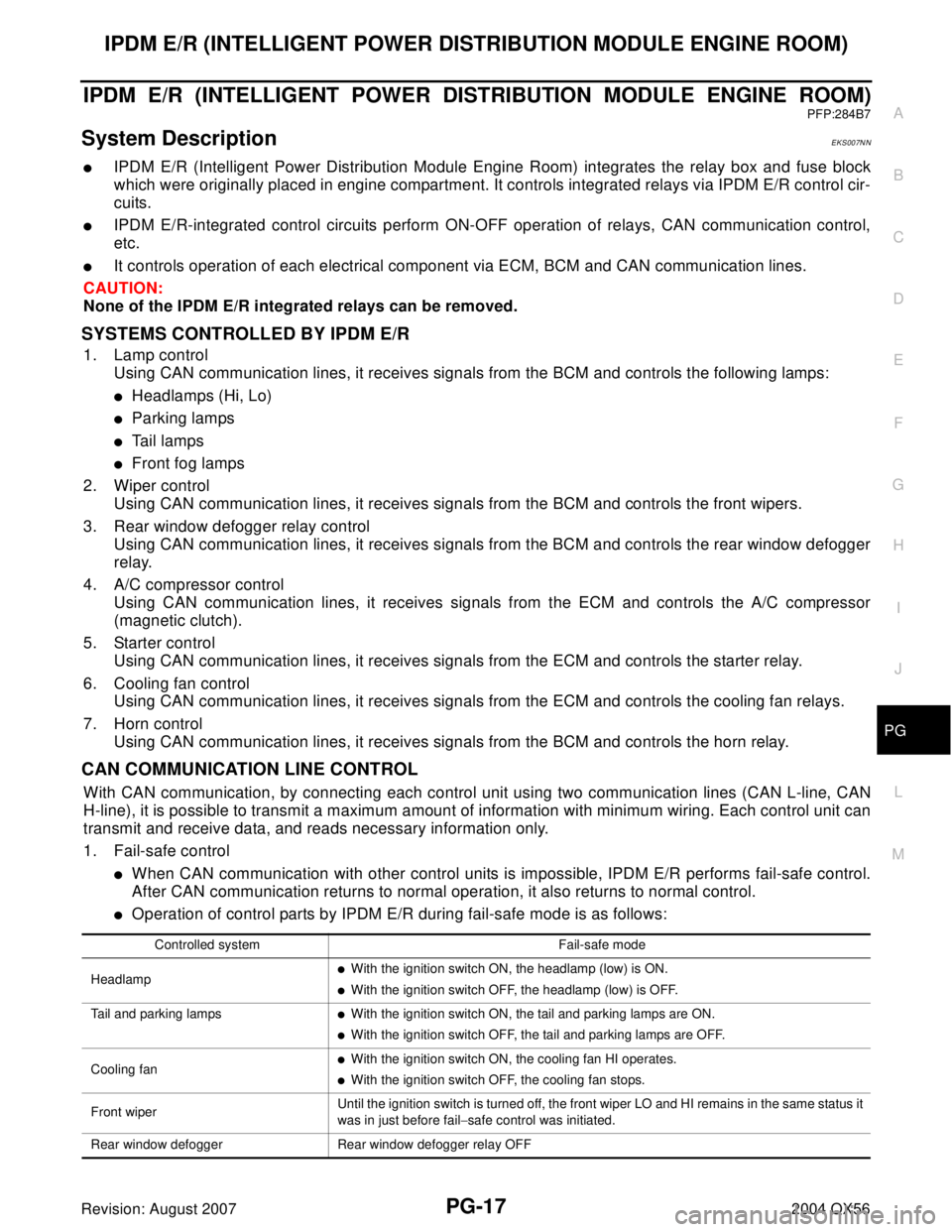
Controlled system Fail-safe mode
Headlamp
�With the ignition switch ON, the headlamp (low) is ON.
�With the ignition switch OFF, the headlamp (low) is OFF.
Tail and parking lamps
�With the ignition switch ON, the tail and parking lamps are ON.
�With the ignition switch OFF, the tail and parking lamps are OFF.
Cooling fan
�With the ignition switch ON, the cooling fan HI operates.
�With the ignition switch OFF, the cooling fan stops.
Front wiperUntil the ignition switch is turned off, the front wiper LO and HI remains in the same status it
was in just before fail−safe control was initiated.
Rear window defogger Rear window defogger relay OFF
Page 2686 of 3371

IPDM E/R (INTELLIGENT POWER DISTRIBUTION MODULE ENGINE ROOM)
PG-27
C
D
E
F
G
H
I
J
L
MA
B
PG
Revision: August 20072004 QX56
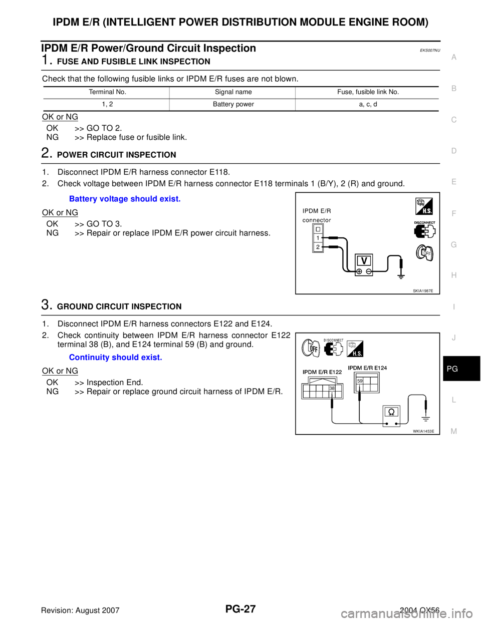
IPDM E/R Power/Ground Circuit InspectionEKS007NU
1. FUSE AND FUSIBLE LINK INSPECTION
Check that the following fusible links or IPDM E/R fuses are not blown.
OK or NG
OK >> GO TO 2.
NG >> Replace fuse or fusible link.
2. POWER CIRCUIT INSPECTION
1. Disconnect IPDM E/R harness connector E118.
2. Check voltage between IPDM E/R harness connector E118 terminals 1 (B/Y), 2 (R) and ground.
OK or NG
OK >> GO TO 3.
NG >> Repair or replace IPDM E/R power circuit harness.
3. GROUND CIRCUIT INSPECTION
1. Disconnect IPDM E/R harness connectors E122 and E124.
2. Check continuity between IPDM E/R harness connector E122
terminal 38 (B), and E124 terminal 59 (B) and ground.
OK or NG
OK >> Inspection End.
NG >> Repair or replace ground circuit harness of IPDM E/R.
Terminal No. Signal name Fuse, fusible link No.
1, 2 Battery power a, c, d
Battery voltage should exist.
SKIA1987E
Continuity should exist.
WKIA1453E
Page 2726 of 3371

ELECTRICAL UNITS LOCATION
PG-67
C
D
E
F
G
H
I
J
L
MA
B
PG
Revision: August 20072004 QX56
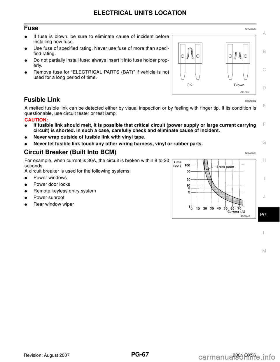
Fuse EKS007O1
�If fuse is blown, be sure to eliminate cause of incident before
installing new fuse.
�Use fuse of specified rating. Never use fuse of more than speci-
fied rating.
�Do not partially install fuse; always insert it into fuse holder prop-
erly.
�Remove fuse for “ELECTRICAL PARTS (BAT)” if vehicle is not
used for a long period of time.
Fusible Link EKS007O2
A melted fusible link can be detected either by visual inspection or by feeling with finger tip. If its condition is
questionable, use circuit tester or test lamp.
CAUTION:
�If fusible link should melt, it is possible that critical circuit (power supply or large current carrying
circuit) is shorted. In such a case, carefully check and eliminate cause of incident.
�Never wrap outside of fusible link with vinyl tape.
�Never let fusible link touch any other wiring harness, vinyl or rubber parts.
Circuit Breaker (Built Into BCM)EKS007O3
For example, when current is 30A, the circuit is broken within 8 to 20
seconds.
A circuit breaker is used for the following systems:
�Power windows
�Power door locks
�Remote keyless entry system
�Power sunroof
�Rear window wiper
CEL083
SBF 2 84 E
Page 2735 of 3371
PG-76
FUSE BLOCK-JUNCTION BOX(J/B)
Revision: August 20072004 QX56
FUSE BLOCK-JUNCTION BOX(J/B)PFP:24350
Terminal ArrangementEKS007O8
WKIA2016E
Page 2736 of 3371
FUSE AND FUSIBLE LINK BOX
PG-77
C
D
E
F
G
H
I
J
L
MA
B
PG
Revision: August 20072004 QX56
FUSE AND FUSIBLE LINK BOXPFP:24381
Terminal ArrangementEKS007O9
WKIA3543E
Page 2737 of 3371
PG-78
FUSE AND RELAY BOX
Revision: August 20072004 QX56
FUSE AND RELAY BOXPFP:24012
Terminal ArrangementEKS007OA
WKIA4248E
Page 2780 of 3371
POWER STEERING OIL PUMP
PS-29
C
D
E
F
H
I
J
K
L
MA
B
PS
Revision: August 20072004 QX56
2. Install oil seal to body assembly using suitable tool.
NOTE:
Do not reuse oil seal.
3. Apply a coat of Genuine NISSAN PSF or equivalent to drive shaft assembly and press drive shaft assem-
bly into body assembly with suitable tool, then install snap ring.
NOTE:
Do not reuse snap ring.
4. Apply a coat of Genuine NISSAN PSF or equivalent to O-ring and install O-ring into body assembly.
NOTE:
Do not reuse O-ring.
5. Install side plate to body assembly.
6. Install lock pin into lock pin hole, and install cam-ring as shown.
�When installing cam ring, align letter "E" to rear cover as
shown.
CAUTION:
Do not confuse the assembling direction of cam ring. If
cam ring is installed facing the incorrect direction, it may
cause pump operation malfunction.
7. Install rotor to body assembly.
SST 0 38 A
SGIA0422E
WGIA0079E