Page 2811 of 3371
RF-10
SUNROOF
Revision: August 20072004 QX56
SUNROOFPFP:91210
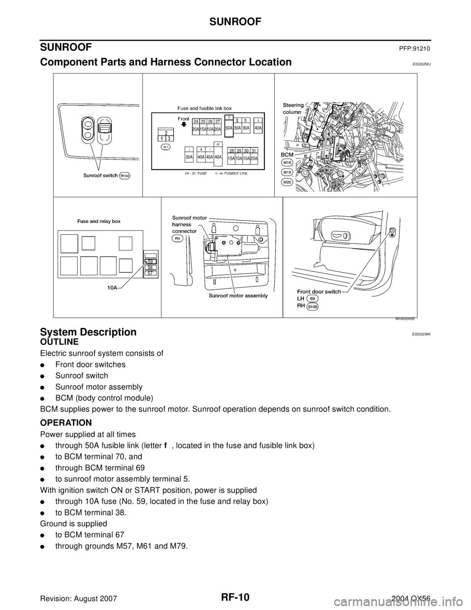
Component Parts and Harness Connector LocationEIS002WJ
System DescriptionEIS002WK
OUTLINE
Electric sunroof system consists of
�Front door switches
�Sunroof switch
�Sunroof motor assembly
�BCM (body control module)
BCM supplies power to the sunroof motor. Sunroof operation depends on sunroof switch condition.
OPERATION
Power supplied at all times
�through 50A fusible link (letter f , located in the fuse and fusible link box)
�to BCM terminal 70, and
�through BCM terminal 69
�to sunroof motor assembly terminal 5.
With ignition switch ON or START position, power is supplied
�through 10A fuse (No. 59, located in the fuse and relay box)
�to BCM terminal 38.
Ground is supplied
�to BCM terminal 67
�through grounds M57, M61 and M79.
WIIA0545E
Page 2819 of 3371

RF-18
SUNROOF
Revision: August 20072004 QX56
BCM Power Supply and Ground Circuit CheckEIS002WV
1. CHECK FUSE
Check the following BCM fuse and fusible link.
NOTE:
Refer to RF-10, "
Component Parts and Harness Connector Location" .
OK or NG
OK >> GO TO 2.
NG >> If fuse is blown, be sure to eliminate cause of problem before installing new fuse. Refer to PG-4,
"POWER SUPPLY ROUTING CIRCUIT" .
2. CHECK POWER SUPPLY CIRCUIT
1. Turn ignition switch OFF.
2. Disconnect BCM connectors.
3. Check voltage between BCM connectors M18 and M20 termi-
nals 38, 70 and ground.
OK or NG
OK >> GO TO 3.
NG >> Repair or replace harness.
3. CHECK GROUND CIRCUIT
Check continuity between BCM connector M20 terminals 67 and
ground.
OK or NG
OK >> Power supply and ground circuits are OK.
NG >> Repair or replace harness.
Retained power operation does not operate properly.1. Check the retained power operation mode settingRF-112. BCM power supply and ground circuit checkRF-18
3. Door switch checkRF-22
4. Replace sunroof motor assemblyRF-27
Motor does not stop at the sunroof fully-open or fully-closed
position.1. Initialization procedure checkRF-11
2. Replace sunroof motor assemblyRF-27
Sunroof does not do the interruption detection. 1. Replace sunroof motor assemblyRF-27
Symptom Diagnostic procedure and repair order Refer to page
Component Parts Terminal No. (SIGNAL) Ampere No. Location
BCM38 (IGN power supply) 10A 59 Fuse and relay box
70 (BAT power supply) 50A f Fuse and fusible link box
ConnectorTerminals
(Wire color)
ConditionVoltage (V)
(Approx.)
(+) (–)
M18 38 (W/L)
GroundIgnition switch ON
Battery voltage
M20 70 (W/B) Ignition switch OFF
WIIA0229E
Connector Terminals (Wire color) Continuity
M20 67 (B) Ground Yes
WIIA0230E
Page 2882 of 3371

TROUBLE DIAGNOSES FOR SYMPTOMS
RSU-23
C
D
F
G
H
I
J
K
L
MA
B
RSU
Revision: August 20072004 QX56
TROUBLE DIAGNOSES FOR SYMPTOMSPFP:99999
Load Leveling Rear Air Suspension System Does Not OperateEES0011D
1. CHECK WARNING LAMP ACTIVATION
Make sure warning lamp remains off while driving.
OK or NG
OK >> GO TO 2.
NG >> Carry out self-diagnosis. Refer to RSU-14, "
SELF-DIAGNOSIS" .
2. CHECK FUSES
�Check that the following fuses are not blown.
OK or NG
OK >> GO TO 3.
NG >> If fuse is blown, be sure to eliminate cause of blown fuse before installing new fuse. Refer to PG-
4, "POWER SUPPLY ROUTING CIRCUIT" .
3. CHECK SUSPENSION CONTROL UNIT POWER AND GROUND
1. Turn the ignition switch ON.
2. Check voltage between suspension control unit connector B3
terminal 6 (G/R) and ground and between suspension control
unit connector B3 terminal 7 (W/L) and ground.
3. Turn ignition switch OFF.
4. Check resistance between suspension control unit connector B3
terminal 16 (B) and ground.
OK or NG
OK >> GO TO 4.
NG >> Repair the circuit.
Unit Terminals Signal name Fuse or Fusible Link
Suspension control unit6 Ignition switch ON or START 12 (10A)
7
Battery power29 (10A)
Compressor motor relay 5 g (30A)
Combination meter24 Ignition switch ON or START 14 (10A)
8 Battery power 19 (10A)
Voltage : Approx. 12V
WEIA0069E
Continuity should exist.
WEIA0070E
Page 2931 of 3371

SC-10
STARTING SYSTEM
Revision: August 20072004 QX56
STARTING SYSTEMPFP:23300
System DescriptionEKS00798
Power is supplied at all times:
�through 40A fusible link (letter m , located in the fuse and fusible link box)
�to ignition switch terminal B.
With the ignition switch in the START position, power is supplied:
�from ignition switch terminal ST
�to IPDM E/R terminal 21.
With the ignition switch in the ON or START position, power is supplied to IPDM E/R (intelligent power distribu-
tion module engine room) CPU.
With the selector lever in the P or N position, power is supplied:
�through A/T assembly terminal 9
�to IPDM E/R terminal 48.
Ground is supplied at all times:
�to IPDM E/R terminals 38 and 59
�from body grounds E9, E15 and E24.
Then the starter relay is turned on.
The IPDM E/R is energized and power is supplied:
�from terminal 19 of the IPDM E/R
�to terminal 1 of the starter motor windings.
The starter motor plunger closes and provides a closed circuit between the battery and the starter motor. The
starter motor is grounded to the cylinder block. With power and ground supplied, the starter motor operates.
Page 2935 of 3371

SC-14
STARTING SYSTEM
Revision: August 20072004 QX56
DIAGNOSTIC PROCEDURE 1
Check Terminal "2" Circuit
1. CHECK POWER SUPPLY FOR STARTER MOTOR “2” TERMINAL
1. Remove the fuel pump fuse.
2. Crank or start the engine (where possible) until the fuel pressure is released.
3. Turn the ignition switch OFF.
4. Check that the starter motor connector F27 connection is clean and tight.
5. Check voltage between starter motor connector F27 terminal 2
(B/R) and ground using a digital circuit tester.
OK or NG
OK >> GO TO 2.
NG >> Check harness between the battery and the starter
motor for open circuit.
2. CHECK BATTERY CABLE CONNECTION QUALITY (VOLTAGE DROP TEST)
Check voltage between starter motor connector F27 terminal 2 (B/R)
and battery positive terminal using a digital circuit tester.
OK or NG
OK >> GO TO 3.
NG >> Check harness between the battery and the starter
motor for poor continuity.
3. CHECK STARTER MOTOR GROUND CIRCUIT (VOLTAGE DROP TEST)
Check voltage between starter motor case and battery negative ter-
minal using a digital circuit tester.
OK or NG
OK >> Starter motor “2” terminal circuit is OK. Further inspec-
tion is necessary. Refer to SC-13, "
WORK FLOW" .
NG >> Check harness between the starter motor case and
ground for poor continuity. Battery voltage should
exist.
WKIA2105E
Ignition switch in
START.: Less than 0.5V
WKIA2106E
Ignition switch in
START.: Less than 0.2V
WKIA2107E
Page 2936 of 3371

STARTING SYSTEM
SC-15
C
D
E
F
G
H
I
J
L
MA
B
SC
Revision: August 20072004 QX56
DIAGNOSTIC PROCEDURE 2
Check Terminal "1" Circuit
1. CHECK POWER SUPPLY FOR STARTER MOTOR “1” TERMINAL
1. Remove the fuel pump fuse.
2. Crank or start the engine (where possible) until the fuel pressure is released.
3. Turn the ignition switch OFF.
4. Disconnect starter motor connector F28.
5. Check voltage between starter motor connector F28 terminal 1
(W/R) and ground using a digital circuit tester.
OK or NG
OK >> GO TO 2.
NG >> Check the following.
�40A fusible link (letter m , located in fuse and fusible
link box)
�Ignition switch
�Starter relay [within the intelligent power distribution module engine room (IPDM E/R)]
�Harness for open or short
2. CHECK “1” TERMINAL CONNECTION QUALITY (VOLTAGE DROP TEST)
1. Turn the ignition switch OFF.
2. Connect starter motor connector F28.
3. Check voltage between starter motor connector F28 terminal 1
(W/R) and battery positive terminal using a digital circuit tester.
OK or NG
OK >> Starter motor “1” terminal circuit is OK. Further inspec-
tion is necessary. Refer to SC-13, "
WORK FLOW" .
NG >> Check harness between the battery and the starter
motor “1” terminal for poor continuity. Ignition switch in
START.: Battery voltage
WKIA2108E
Ignition switch in
START.: Less than 1V
WKIA1792E
Page 2938 of 3371

CHARGING SYSTEM
SC-17
C
D
E
F
G
H
I
J
L
MA
B
SC
Revision: August 20072004 QX56
CHARGING SYSTEMPFP:23100
System DescriptionEKS0079E
The generator provides DC voltage to operate the vehicle's electrical system and to keep the battery charged.
The voltage output is controlled by the IC regulator.
Power is supplied at all times to generator terminal 4 through:
�10A fuse (No. 30, located in the fuse and fusible link box).
Terminal 1 supplies power to charge the battery and operate the vehicle's electrical system. Output voltage is
controlled by the IC regulator at terminal 4 detecting the input voltage. The charging circuit is protected by the
140A fusible link (letter a , located in the fusible link box).
Ground is supplied:
�to generator terminal 2
�through body ground E203.
With the ignition switch in the ON or START position, power is supplied:
�through 10A fuse [No. 14, located in the fuse block (J/B)]
�to combination meter terminal 24 for the charge warning lamp.
Ground is supplied to terminal 13 of the combination meter through terminal 3 of the generator. With power
and ground supplied, the charge warning lamp will illuminate. When the generator is providing sufficient volt-
age with the engine running, the ground is opened and the charge warning lamp will go off.
If the charge warning lamp illuminates with the engine running, a fault is indicated.
Page 2943 of 3371
SC-22
CHARGING SYSTEM
Revision: August 20072004 QX56
DIAGNOSTIC PROCEDURE 1
Check Terminal "3" Circuit
1. CHECK “3” TERMINAL CONNECTION
1. Turn the ignition switch OFF.
2. Check to see if “3” terminal is clean and tight.
OK or NG
OK >> GO TO 2.
NG >> Repair “3” terminal connection. Confirm repair by performing complete Battery/Starting/Charging
system test.
2. CHECK “3” TERMINAL CIRCUIT
1. Disconnect E205 connector from generator.
2. Apply ground to connector E205 terminal 3 (BR/W) with the igni-
tion switch in the ON position.
OK or NG
OK >> GO TO SC-21, "WORK FLOW" .
NG >> Check the following.
�10A fuse [No. 14, located in fuse block (J/B)]
�CHARGE lamp
�Harness for open or short between combination
meter and fuse
�Harness for open or short between combination meter and generator CHARGE lamp should light up.
WKIA2110E