Page 1210 of 3371

PRECAUTIONS
EC-19
C
D
E
F
G
H
I
J
K
L
MA
EC
Revision: August 20072004 QX56
�Do not operate fuel pump when there is no fuel in lines.
�Tighten fuel hose clamps to the specified torque.
�Do not depress accelerator pedal when starting.
�Immediately after starting, do not rev up engine unneces-
sarily.
�Do not rev up engine just prior to shutdown.
�When installing C.B. ham radio or a mobile phone, be sure
to observe the following as it may adversely affect elec-
tronic control systems depending on installation location.
–Keep the antenna as far as possible from the electronic
control units.
–Keep the antenna feeder line more than 20 cm (8 in) away
from the harness of electronic controls.
Do not let them run parallel for a long distance.
–Adjust the antenna and feeder line so that the standing-
wave radio can be kept smaller.
–Be sure to ground the radio to vehicle body.
Wiring Diagrams and Trouble DiagnosisUBS00GZ8
When you read wiring diagrams, refer to the following:
�GI-15, "How to Read Wiring Diagrams"
�PG-4, "POWER SUPPLY ROUTING CIRCUIT" for power distribution circuit
When you perform trouble diagnosis, refer to the following:
�GI-11, "HOW TO FOLLOW TEST GROUPS IN TROUBLE DIAGNOSES"
�GI-27, "How to Perform Efficient Diagnosis for an Electrical Incident"
BBIA0402E
SEF 7 09 Y
SEF 7 08 Y
Page 1214 of 3371
ENGINE CONTROL SYSTEM
EC-23
C
D
E
F
G
H
I
J
K
L
MA
EC
Revision: August 20072004 QX56
ENGINE CONTROL SYSTEMPFP:23710
System DiagramUBS00GZB
PBIB2051E
Page 1215 of 3371
EC-24Revision: August 2007
ENGINE CONTROL SYSTEM
2004 QX56
Vacuum Hose DrawingUBS00GZC
Refer to EC-23, "System Diagram" for Vacuum Control System.
PBIB2052E
Page 1232 of 3371
 SENSOR 1 HARNESS
1. Turn ignition switch OFF and disconnect battery ground cable.")
BASIC SERVICE PROCEDURE
EC-41
C
D
E
F
G
H
I
J
K
L
MA
EC
Revision: August 20072004 QX56
21. CHECK AIR FUEL RATIO (A/F) SENSOR 1 HARNESS
1. Turn ignition switch OFF and disconnect battery ground cable.
2. Disconnect ECM harness connector.
3. Disconnect A/F sensor 1 harness connector.
4. Check harness continuity between the following terminals. Refer to EC-431, "
Wiring Diagram" .
5. Also check harness for short to ground and short to power.
OK or NG
OK >> GO TO 22.
NG >> 1. Repair open circuit or short to ground or short to power in harness or connectors between ECM
and A/F sensor 1.
2. GO TO 4.
22. PERFORM ACCELERATOR PEDAL RELEASED POSITION LEARNING
1. Reconnect ECM harness connector.
2. Perform EC-44, "
Accelerator Pedal Released Position Learning" .
>> GO TO 23.
23. PERFORM THROTTLE VALVE CLOSED POSITION LEARNING
Perform EC-44, "
Throttle Valve Closed Position Learning" .
>> GO TO 24.
24. PERFORM IDLE AIR VOLUME LEARNING
Refer to EC-44, "
Idle Air Volume Learning" .
Is Idle Air Volume Learning carried out successfully?
Ye s o r N o
Yes (With CONSULT-II)>>GO TO 25.
Yes (Without CONSULT-II)>>GO TO 26.
No >> 1. Follow the instruction of Idle Air Volume Learning.
2. GO TO 4.
Bank 1 Bank 2
A/F sensor 1 terminal ECM terminal A/F sensor 1 terminal ECM terminal
1161 76
275277
42424
535557
656658
Continuity should exist.
Page 1285 of 3371
EC-94Revision: August 2007
TROUBLE DIAGNOSIS
2004 QX56
Circuit DiagramUBS00H02
BBWA1788E
Page 1319 of 3371
EC-128Revision: August 2007
POWER SUPPLY AND GROUND CIRCUIT
2004 QX56
POWER SUPPLY AND GROUND CIRCUITPFP:24110
Wiring DiagramUBS00H0F
BBWA11 55 E
Page 1321 of 3371
EC-130Revision: August 2007
POWER SUPPLY AND GROUND CIRCUIT
2004 QX56
4. DETECT MALFUNCTIONING PART
Check the following.
�10A fuse
�Harness for open or short between ECM and ignition switch
>> Repair harness or connectors.
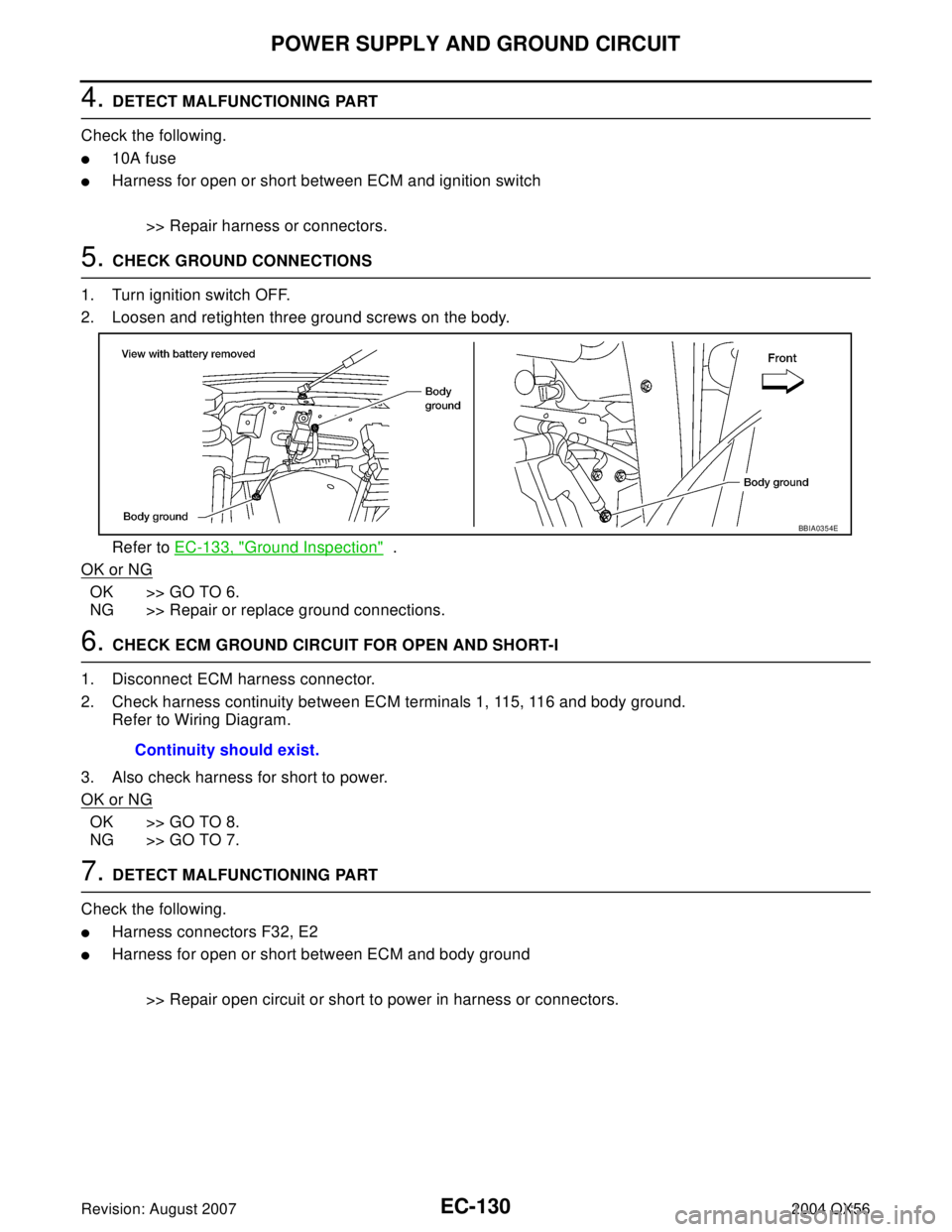
5. CHECK GROUND CONNECTIONS
1. Turn ignition switch OFF.
2. Loosen and retighten three ground screws on the body.
Refer to EC-133, "
Ground Inspection" .
OK or NG
OK >> GO TO 6.
NG >> Repair or replace ground connections.
6. CHECK ECM GROUND CIRCUIT FOR OPEN AND SHORT-I
1. Disconnect ECM harness connector.
2. Check harness continuity between ECM terminals 1, 115, 116 and body ground.
Refer to Wiring Diagram.
3. Also check harness for short to power.
OK or NG
OK >> GO TO 8.
NG >> GO TO 7.
7. DETECT MALFUNCTIONING PART
Check the following.
�Harness connectors F32, E2
�Harness for open or short between ECM and body ground
>> Repair open circuit or short to power in harness or connectors.
BBIA0354E
Continuity should exist.
Page 1323 of 3371

EC-132Revision: August 2007
POWER SUPPLY AND GROUND CIRCUIT
2004 QX56
11 . CHECK ECM POWER SUPPLY CIRCUIT-V
1. Disconnect ECM harness connector.
2. Disconnect IPDM E/R harness connector E119.
3. Check harness continuity between ECM terminals 119, 120 and IPDM E/R terminal 3.
Refer to Wiring Diagram.
4. Also check harness for short to ground and short to power.
OK or NG
OK >> GO TO 14.
NG >> Repair open circuit or short to ground or short to power in harness or connectors.
12. CHECK ECM POWER SUPPLY CIRCUIT-VI
1. Disconnect ECM harness connector.
2. Disconnect IPDM E/R harness connector E119.
3. Check harness continuity between ECM terminal 111 and IPDM E/R terminal 7.
Refer to Wiring Diagram.
4. Also check harness for short to ground and short to power.
OK or NG
OK >> GO TO 13.
NG >> Repair open circuit or short to ground or short to power in harness or connectors.
13. CHECK 20A FUSE
Check 20A fuse (No. 53, located in the IPDM E/R).
OK or NG
OK >> GO TO 17.
NG >> Replace 20A fuse.
14. CHECK GROUND CONNECTIONS
1. Turn ignition switch OFF.
2. Loosen and retighten three ground screws on the body.
Refer to EC-133, "
Ground Inspection" .
OK or NG
OK >> GO TO 15.
NG >> Repair or replace ground connections.Continuity should exist.
Continuity should exist.
BBIA0354E