Page 873 of 3371
BL-108
AUTOMATIC BACK DOOR SYSTEM
Revision: August 20072004 QX56
Wiring Diagram — B/CLOS —EIS002SX
WIWA0863E
Page 906 of 3371
IVIS (INFINITI VEHICLE IMMOBILIZER SYSTEM-NATS)
BL-141
C
D
E
F
G
H
J
K
L
MA
B
BL
Revision: August 20072004 QX56
Wiring Diagram — NATS —EIS002TP
WIWA1079E
Page 911 of 3371

Revision: August 20072004 QX56
Trouble DiagnosesEIS002TT
SYMPTOM MATRIX CHART 1
Self-diagnosis related item
*: When IVIS (NATS) detects trouble,")
BL-146
IVIS (INFINITI VEHICLE IMMOBILIZER SYSTEM-NATS)
Revision: August 20072004 QX56
Trouble DiagnosesEIS002TT
SYMPTOM MATRIX CHART 1
Self-diagnosis related item
*: When IVIS (NATS) detects trouble, the security indicator lights up while ignition key is in the “ON” position.SymptomDisplayed “SELF-DIAG
RESULTS” on CON-
SULT-II screen.Diagnostic Procedure
(Reference page)System
(Malfunctioning part or
mode)Reference Part No. Of
Illustration On System
Diagram
�Security indicator
lighting up*
�Engine cannot be
startedCHAIN OF ECM-IMMU
[P1612]PROCEDURE 1
(BL-148
)In rare case, “CHAIN OF
ECM-IMMU” might be
stored during key regis-
tration procedure, even if
the system is not mal-
functioning.—
Open circuit in battery
voltage line of BCM cir-
cuitC1
Open circuit in ignition
line of BCM circuitC2
Open circuit in ground
line of BCM circuitC3
Open or short circuit
between BCM and ECM
communication lineC4
ECM B
BCM A
DIFFERENCE OF KEY
[P1615]PROCEDURE 2
(BL-149
)Unregistered key D
BCM A
CHAIN OF IMMU-KEY
[P1614]PROCEDURE 5
(BL-152
)Malfunction of key ID
chipE5
Communication line
between ANT/ AMP and
BCM:
Open circuit or short cir-
cuit of battery voltage
line or ground lineE1
E2
Open circuit in power
source line of ANT/ AMP
circuitE3
Open circuit in ground
line of ANT/ AMP circuitE4
NATS antenna amp. E6
BCM A
ID DISCORD, IMM-ECM
[P1611]PROCEDURE 3
(BL-150
)System initialization has
not yet been completed.F
ECM B
LOCK MODE
[P1610]PROCEDURE 4
(BL-151
)LOCK MODE D
Security indicator light-
ing up*DON'T ERASE
BEFORE CHECKING
ENG DIAGWORK FLOW
(BL-145
)Engine trouble data and
IVIS (NATS) trouble data
have been detected in
ECM—
Page 912 of 3371
IVIS (INFINITI VEHICLE IMMOBILIZER SYSTEM-NATS)
BL-147
C
D
E
F
G
H
J
K
L
MA
B
BL
Revision: August 20072004 QX56
SYMPTOM MATRIX CHART 2
Non self-diagnosis related item
*: CONSULT-II self-diagnostic results display screen “no malfunction is detected”.
DIAGNOSTIC SYSTEM DIAGRAM
SymptomDiagnostic Procedure
(Reference page)System
(Malfunctioning part or mode)Reference Part No. Of Illustra-
tion On System Diagram
Security indicator does not light
up*.PROCEDURE 6
(BL-155
)Combination meter (security
indictor lamp)—
Open circuit between fuse and
BCM—
BCM A
WIIA0550E
Page 922 of 3371
HOMELINK UNIVERSAL TRANSCEIVER
BL-157
C
D
E
F
G
H
J
K
L
MA
B
BL
Revision: August 20072004 QX56
HOMELINK UNIVERSAL TRANSCEIVERPFP:96401
Wiring Diagram — TRNSCV —EIS002U1
WIWA1080E
Page 1014 of 3371

BRC-1
BRAKE CONTROL SYSTEM
F BRAKES
CONTENTS
C
D
E
G
H
I
J
K
L
M
SECTION BRC
A
B
BRC
Revision: August 20072004 QX56VDC/TCS/ABS
PRECAUTIONS .......................................................... 3
Precautions for Supplemental Restraint System
(SRS) “AIR BAG” and “SEAT BELT PRE-TEN-
SIONER” .................................................................. 3
Precautions for Brake System .................................. 3
Precautions When Using CONSULT-II ..................... 3
CHECK POINTS FOR USING CONSULT-II ......... 3
Precautions for Brake Control .................................. 4
Precautions for CAN System ................................... 4
Wiring Diagrams and Trouble Diagnosis .................. 5
PREPARATION ........................................................... 6
Special Service Tool ................................................. 6
Commercial Service Tools ........................................ 6
SYSTEM DESCRIPTION ............................................ 7
System Components ................................................ 7
ABS Function ........................................................... 8
EBD Function ........................................................... 8
TCS Function ........................................................... 8
VDC Function ........................................................... 8
Fail-Safe Function .................................................... 8
ABS/EBD SYSTEM ............................................... 9
VDC/TCS SYSTEM ............................................... 9
ACTIVE BOOSTER ............................................... 9
Hydraulic Circuit Diagram ........................................ 9
CAN COMMUNICATION .......................................... 10
System Description ................................................ 10
TROUBLE DIAGNOSIS .............................................11
How to Perform Trouble Diagnoses for Quick and
Accurate Repair ......................................................11
INTRODUCTION ..................................................11
WORK FLOW ...................................................... 12
CLARIFY CONCERN .......................................... 13
EXAMPLE OF DIAGNOSIS SHEET ................... 13
Component Parts and Harness Connector Location ... 14
Schematic .............................................................. 15
Wiring Diagram — VDC — ..................................... 16
Basic Inspection ..................................................... 23
BRAKE FLUID LEVEL, FLUID LEAK, AND
BRAKE PAD INSPECTION ................................. 23POWER SYSTEM TERMINAL LOOSENESS
AND BATTERY INSPECTION ............................. 23
ABS WARNING LAMP, SLIP INDICATOR LAMP
AND VDC OFF INDICATOR LAMP INSPECTION ... 23
Warning Lamp and Indicator Timing ....................... 24
Control Unit Input/Output Signal Standard ............. 24
REFERENCE VALUE FROM CONSULT-II ......... 24
CONSULT-II Function (ABS) .................................. 28
CONSULT-II BASIC OPERATION PROCEDURE
... 28
SELF-DIAGNOSIS .............................................. 29
DATA MONITOR ................................................. 32
ACTIVE TEST ..................................................... 36
TROUBLE DIAGNOSIS FOR SELF-DIAGNOSTIC
ITEMS ........................................................................ 38
Wheel Sensor System Inspection ........................... 38
Engine System Inspection ...................................... 39
ABS/TCS/VDC Control Unit Inspection .................. 40
Steering Angle Sensor System ............................... 40
Yaw Rate/Side/Decel G Sensor System Inspection ... 41
Solenoid and VDC Change-Over Valve System
Inspection ............................................................... 43
Actuator Motor, Motor Relay, and Circuit Inspection ... 44
Stop Lamp Switch System Inspection .................... 45
ABS/TCS/VDC Control Unit Power and Ground
Systems Inspection ................................................ 46
Brake Fluid Level Switch System Inspection .......... 47
Active Booster System Inspection .......................... 48
Delta Stroke Sensor System Inspection ................. 49
Pressure Sensor System Inspection ...................... 51
Steering Angle Sensor Safe Mode Inspection ........ 53
CAN Communication System Inspection ................ 54
ICC System Inspection ........................................... 54
Inspection For Self-diagnosis Result "ST ANGLE
SEN SIGNAL" ......................................................... 55
Inspection For Self-diagnosis Result "DECEL G
SEN SET" ............................................................... 55
VDC OFF Indicator lamp Does Not Illuminate ........ 55
Component Inspection ............................................ 56
VDC OFF SWITCH ............................................. 56
Page 1018 of 3371
PRECAUTIONS
BRC-5
[VDC/TCS/ABS]
C
D
E
G
H
I
J
K
L
MA
B
BRC
Revision: August 20072004 QX56
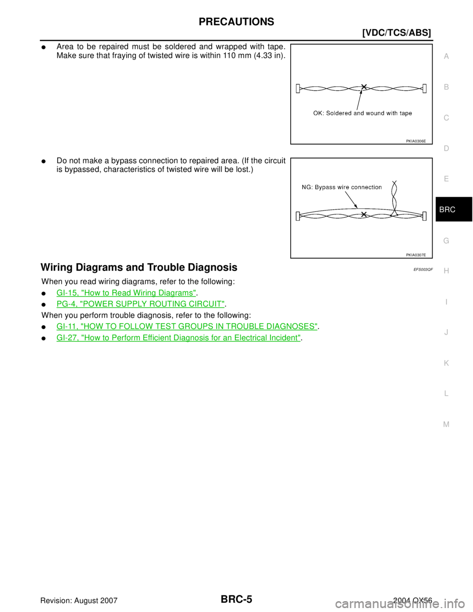
�Area to be repaired must be soldered and wrapped with tape.
Make sure that fraying of twisted wire is within 110 mm (4.33 in).
�Do not make a bypass connection to repaired area. (If the circuit
is bypassed, characteristics of twisted wire will be lost.)
Wiring Diagrams and Trouble Diagnosis EF S0 03 QF
When you read wiring diagrams, refer to the following:
�GI-15, "How to Read Wiring Diagrams".
�PG-4, "POWER SUPPLY ROUTING CIRCUIT".
When you perform trouble diagnosis, refer to the following:
�GI-11, "HOW TO FOLLOW TEST GROUPS IN TROUBLE DIAGNOSES".
�GI-27, "How to Perform Efficient Diagnosis for an Electrical Incident".
PKIA0306E
PKIA0307E
Page 1022 of 3371
![INFINITI QX56 2004 Factory Service Manual SYSTEM DESCRIPTION
BRC-9
[VDC/TCS/ABS]
C
D
E
G
H
I
J
K
L
MA
B
BRC
Revision: August 20072004 QX56
ABS/EBD SYSTEM
In case of an electrical malfunction with the ABS, the ABS warning lamp, VDC OFF indicat](/manual-img/42/57034/w960_57034-1021.png "INFINITI QX56 2004 Factory Service Manual SYSTEM DESCRIPTION
BRC-9
[VDC/TCS/ABS]
C
D
E
G
H
I
J
K
L
MA
B
BRC
Revision: August 20072004 QX56
ABS/EBD SYSTEM
In case of an electrical malfunction with the ABS, the ABS warning lamp, VDC OFF indicat")
SYSTEM DESCRIPTION
BRC-9
[VDC/TCS/ABS]
C
D
E
G
H
I
J
K
L
MA
B
BRC
Revision: August 20072004 QX56
ABS/EBD SYSTEM
In case of an electrical malfunction with the ABS, the ABS warning lamp, VDC OFF indicator lamp and SLIP
indicator lamp will turn on. In case of an electrical malfunction with the EBD system, the BRAKE warning lamp,
ABS warning lamp, VDC OFF indicator lamp and SLIP indicator lamp will turn on.
The system will revert to one of the following conditions of the Fail-Safe function.
1. For ABS malfunction, only the EBD is operative and the condition of the vehicle is the same condition of
vehicles without ABS/TCS/VDC system.
2. For EBD malfunction, the EBD and ABS become inoperative, and the condition of the vehicle is the same
as the condition of vehicles without ABS/TCS/VDC or EBD system.
VDC/TCS SYSTEM
In case of TCS/VDC system malfunction, the VDC OFF indicator lamp and SLIP indicator lamp are turned on
and the condition of the vehicle is the same as the condition of vehicles without TCS/VDC system. In case of
an electrical malfunction with the TCS/VDC system, the ABS control continues to operate normally without
TCS/VDC control.
ACTIVE BOOSTER
The active brake booster consists of a vacuum booster, an active booster control group and a delta stroke
sensor. In case of brake booster system malfunction due to loss of vacuum, the delta stroke sensor will signal
the ABS actuator and electric unit (control unit) that a booster failure has occurred. The active booster then
applies supplemental force to the master cylinder relative to the amount of force exerted on the brake pedal.
Hydraulic Circuit DiagramEFS003QO
WFIA0187E


BL-141
C
D
E
F
G
H
J
K
L
MA
B
BL
Revision: August 20072004 QX56
Wiring Diagram — NATS —EIS002TP
WIWA1079E")

BL-147
C
D
E
F
G
H
J
K
L
MA
B
BL
Revision: August 20072004 QX56
SYMPTOM MATRIX CHART 2
Non self-diagnosis related item
*: CONSULT-II self-diagnostic res")