Page 1383 of 3371
EC-192Revision: August 2007
DTC P0138, P0158 HO2S2
2004 QX56
2. CHECK HO2S2 GROUND CIRCUIT FOR OPEN AND SHORT
1. Disconnect heated oxygen sensor 2 harness connector.
2. Check harness continuity between HO2S2 terminal 4 and body ground.
Refer to Wiring Diagram.
3. Also check harness for short to power.
OK or NG
OK >> GO TO 4.
NG >> GO TO 3.
3. DETECT MALFUNCTIONING PART
Check the following.
�Harness connectors E5, F14
�Harness for open or short between heated oxygen sensor 2 and body ground
>> Repair open circuit or short to power in harness or connectors. Continuity should exist.
BBIA0435E
Page 1384 of 3371

DTC P0138, P0158 HO2S2
EC-193
C
D
E
F
G
H
I
J
K
L
MA
EC
Revision: August 20072004 QX56
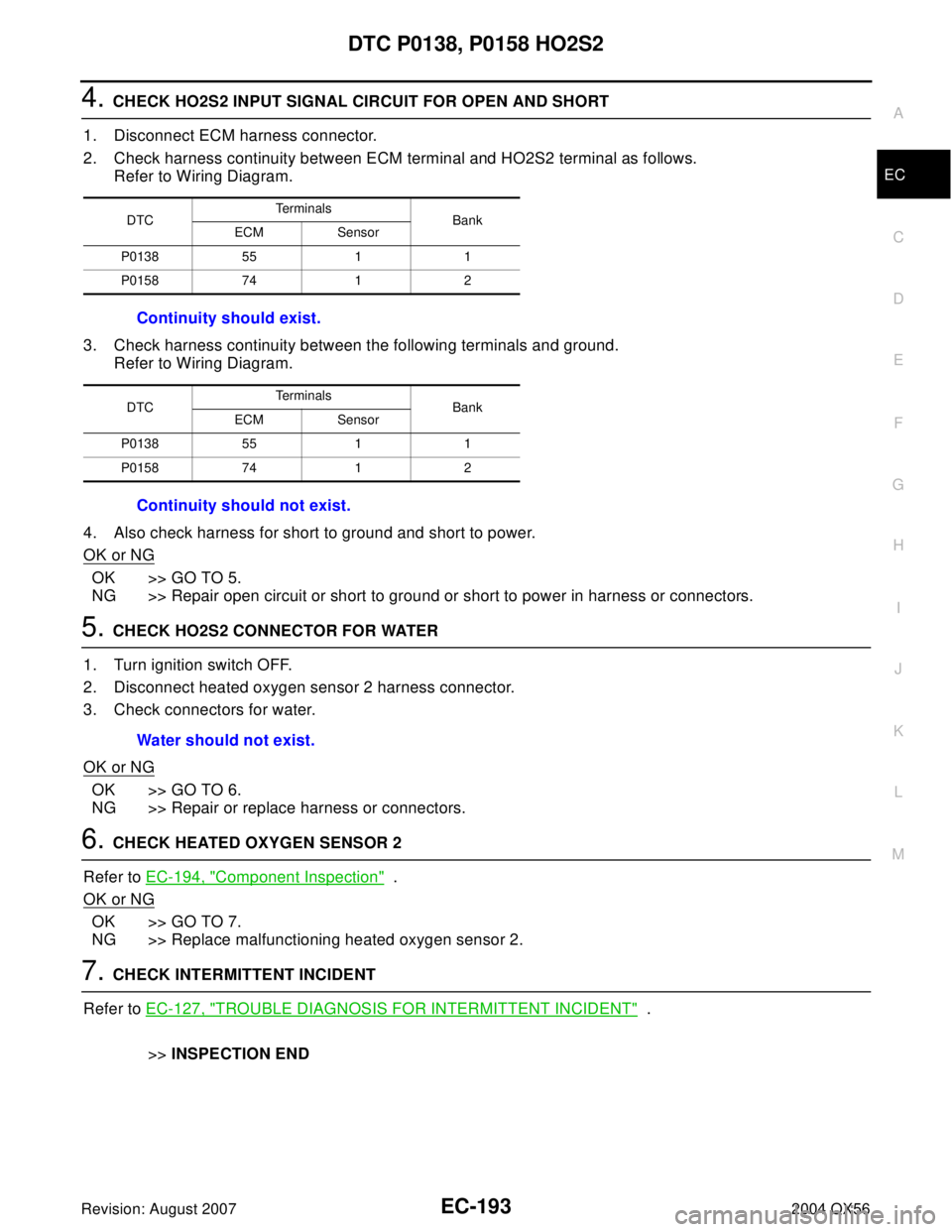
4. CHECK HO2S2 INPUT SIGNAL CIRCUIT FOR OPEN AND SHORT
1. Disconnect ECM harness connector.
2. Check harness continuity between ECM terminal and HO2S2 terminal as follows.
Refer to Wiring Diagram.
3. Check harness continuity between the following terminals and ground.
Refer to Wiring Diagram.
4. Also check harness for short to ground and short to power.
OK or NG
OK >> GO TO 5.
NG >> Repair open circuit or short to ground or short to power in harness or connectors.
5. CHECK HO2S2 CONNECTOR FOR WATER
1. Turn ignition switch OFF.
2. Disconnect heated oxygen sensor 2 harness connector.
3. Check connectors for water.
OK or NG
OK >> GO TO 6.
NG >> Repair or replace harness or connectors.
6. CHECK HEATED OXYGEN SENSOR 2
Refer to EC-194, "
Component Inspection" .
OK or NG
OK >> GO TO 7.
NG >> Replace malfunctioning heated oxygen sensor 2.
7. CHECK INTERMITTENT INCIDENT
Refer to EC-127, "
TROUBLE DIAGNOSIS FOR INTERMITTENT INCIDENT" .
>>INSPECTION END
DTCTe r m i n a l s
Bank
ECM Sensor
P0138 55 1 1
P0158 74 1 2
Continuity should exist.
DTCTe r m i n a l s
Bank
ECM Sensor
P0138 55 1 1
P0158 74 1 2
Continuity should not exist.
Water should not exist.
Page 1390 of 3371
DTC P0139, P0159 HO2S2
EC-199
C
D
E
F
G
H
I
J
K
L
MA
EC
Revision: August 20072004 QX56
Wiring DiagramUBS00H2S
BANK 1
BBWA11 58 E
Page 1395 of 3371
EC-204Revision: August 2007
DTC P0139, P0159 HO2S2
2004 QX56
3. CHECK HO2S2 GROUND CIRCUIT FOR OPEN AND SHORT
1. Turn ignition switch OFF.
2. Disconnect heated oxygen sensor 2 harness connector.
3. Check harness continuity between HO2S2 terminal 4 and body ground.
Refer to Wiring Diagram.
4. Also check harness for short to power.
OK or NG
OK >> GO TO 5.
NG >> GO TO 4.
4. DETECT MALFUNCTIONING PART
Check the following.
�Harness connectors E5, F14
�Harness for open or short between heated oxygen sensor 2 and body ground
>> Repair open circuit or short to power in harness or connectors. Continuity should exist.
BBIA0435E
Page 1396 of 3371

DTC P0139, P0159 HO2S2
EC-205
C
D
E
F
G
H
I
J
K
L
MA
EC
Revision: August 20072004 QX56
5. CHECK HO2S2 INPUT SIGNAL CIRCUIT FOR OPEN AND SHORT
1. Disconnect ECM harness connector.
2. Check harness continuity between ECM terminal and HO2S2 terminal as follows.
Refer to Wiring Diagram.
3. Check harness continuity between the following terminals and ground.
Refer to Wiring Diagram.
4. Also check harness for short to ground and short to power.
OK or NG
OK >> GO TO 6.
NG >> Repair open circuit or short to ground or short to power in harness or connectors.
6. CHECK HEATED OXYGEN SENSOR 2
Refer to EC-205, "
Component Inspection" .
OK or NG
OK >> GO TO 7.
NG >> Replace malfunctioning heated oxygen sensor 2.
7. CHECK INTERMITTENT INCIDENT
Refer to EC-127, "
TROUBLE DIAGNOSIS FOR INTERMITTENT INCIDENT" .
>>INSPECTION END
Component InspectionUBS00H2U
HEATED OXYGEN SENSOR 2
With CONSULT-II
1. Turn ignition switch ON and select “DATA MONITOR” mode with
CONSULT-II.
2. Start engine and warm it up to the normal operating tempera-
ture.
3. Turn ignition switch OFF and wait at least 10 seconds.
4. Start engine and keep the engine speed between 3,500 and
4,000 rpm for at least 1 minute under no load.
5. Let engine idle for 1 minute.
DTCTe r m i n a l s
Bank
ECM Sensor
P0139 55 1 1
P0159 74 1 2
Continuity should exist.
DTCTe r m i n a l s
Bank
ECM Sensor
P0139 55 1 1
P0159 74 1 2
Continuity should not exist.
SEF 1 74 Y
Page 1401 of 3371
EC-210Revision: August 2007
DTC P0171, P0174 FUEL INJECTION SYSTEM FUNCTION
2004 QX56
Wiring DiagramUBS00H2Y
BANK 1
BBWA11 62 E
Page 1404 of 3371
DTC P0171, P0174 FUEL INJECTION SYSTEM FUNCTION
EC-213
C
D
E
F
G
H
I
J
K
L
MA
EC
Revision: August 20072004 QX56
3. CHECK A/F SENSOR 1 INPUT SIGNAL CIRCUIT
1. Turn ignition switch OFF.
2. Disconnect corresponding A/F sensor 1 harness connector.
3. Disconnect ECM harness connector.
4. Check harness continuity between the following terminals.
Refer to Wiring Diagram.
5. Check harness continuity between the following terminals and ground.
Refer to Wiring Diagram.
6. Also check harness for short to power.
OK or NG
OK >> GO TO 4.
NG >> Repair open circuit or short to ground or short to power in harness or connectors.
A/F sensor 1 terminal ECM terminal
Bank1116
275
535
656
Bank 2176
277
557
658
Continuity should exist.
Bank 1 Bank 2
A/F sensor 1 terminal ECM terminal A/F sensor 1 terminal ECM terminal
116176
275277
535557
656658
Continuity should not exist.
BBIA0376E
Page 1410 of 3371
DTC P0172, P0175 FUEL INJECTION SYSTEM FUNCTION
EC-219
C
D
E
F
G
H
I
J
K
L
MA
EC
Revision: August 20072004 QX56
Wiring DiagramUBS00H32
BANK 1
BBWA11 62 E