Page 85 of 4449

AT-8
PRECAUTIONS
Revision: 2004 November 2004 FX35/FX45
Precautions ACS002L6
�Before connecting or disconnecting the A/T assembly har-
ness connector, turn ignition switch “OFF” and disconnect
the battery cable from the negative terminal. Because bat-
tery voltage is applied to TCM even if ignition switch is
turned “OFF”.
�After performing each TROUBLE DIAGNOSIS, perform
“DTC (Diagnostic Trouble Code) Confirmation Procedure”.
If the repair is completed the DTC should not be displayed
in the “DTC Confirmation Procedure”.
�Always use the specified brand of ATF. Refer to MA-12, "Fluids and Lubricants" .
�Use paper rags not cloth rags during work.
�After replacing the ATF, dispose of the waste oil using the methods prescribed by law, ordinance, etc.
�Before proceeding with disassembly, thoroughly clean the outside of the transmission. It is important to
prevent the internal parts from becoming contaminated by dirt or other foreign matter.
�Disassembly should be done in a clean work area.
�Use lint-free cloth or towels for wiping parts clean. Common shop rags can leave fibers that could interfere
with the operation of the transmission.
�Place disassembled parts in order for easier and proper assembly.
�All parts should be carefully cleaned with a general purpose, non-flammable solvent before inspection or
reassembly.
�Gaskets, seals and O-rings should be replaced any time the transmission is disassembled.
�It is very important to perform functional tests whenever they are indicated.
�The valve body contains precision parts and requires extreme care when parts are removed and serviced.
Place disassembled valve body parts in order for easier and proper assembly. Care will also prevent
springs and small parts from becoming scattered or lost.
�Properly installed valves, sleeves, plugs, etc. will slide along bores in valve body under their own weight.
�Before assembly, apply a coat of recommended ATF to all parts. Apply petroleum jelly to protect O-rings
and seals, or hold bearings and washers in place during assembly. Do not use grease.
�Extreme care should be taken to avoid damage to O-rings, seals and gaskets when assembling.
�After overhaul, refill the transmission with new ATF.
�When the A/T drain plug is removed, only some of the fluid is drained. Old A/T fluid will remain in torque
converter and ATF cooling system.
Always follow the procedures under “Changing A/T Fluid” in the AT section when changing A/T fluid. Refer
to AT- 1 2 , "
Changing A/T Fluid" , AT- 1 2 , "Checking A/T Fluid" .
SEF289H
SEF217U
Page 89 of 4449

AT-12
A/T FLUID
Revision: 2004 November 2004 FX35/FX45
A/T FLUIDPFP:KLE40
Changing A/T FluidACS0079Z
1. Warm up ATF.
2. Stop engine.
3. Loosen the level gauge bolt.
4. Drain ATF from drain plug and refill with new ATF. Always refill
same volume with drained fluid.
�To replace the ATF, pour in new fluid at the charging pipe with
the engine idling and at the same time drain the old fluid from
the radiator cooler hose return side.
�When the color of the fluid coming out is about the same as
the color of the new fluid, the replacement is complete. The
amount of new transmission fluid to use should be 30 to 50%
increase of the stipulated amount.
CAUTION:
�Use only Genuine Nissan Matic J ATF. Do not mix with other fluid.
�Using automatic transmission fluid other than Genuine Nissan Matic J ATF will cause deteriora-
tion in drive ability and automatic transmission durability, and may damage the automatic trans-
mission, which is not covered by the warranty.
�When filling ATF, take care not to splash heat generating parts such as exhaust with ATF.
�Do not reuse drain plug gasket.
5. Run engine at idle speed for 5 minutes.
6. Check fluid level and condition. Refer to AT- 1 2 , "
Checking A/T Fluid" . If fluid is still dirty, repeat step 2
through 5.
7. Install the removed A/T fluid level gauge in the A/T fluid charging pipe.
8. Tighten the level gauge bolt.
Checking A/T FluidACS007A0
1. Warm up engine.
2. Check for fluid leakage.
3. Loosen the level gauge bolt.
4. Before driving, fluid level can be checked at fluid temperatures
of 30 to 50°C (86 to 122°F) using “COLD” range on A/T fluid
level gauge as follows.
a. Park vehicle on level surface and set parking brake.
b. Start engine and move selector lever through each gear posi-
tion. Leave selector lever in “P” position.
c. Check fluid level with engine idling.
d. Remove A/T fluid level gauge and wipe clean with lint-free
paper.
CAUTION:
When wiping away the A/T fluid level gauge, always use
lint-free paper, not a cloth one.A/T fluid: Genuine Nissan Matic J ATF
Fluid capacity: 10.3 (10-7/8 US qt, 9-1/8 lmp qt)
Drain plug:
: 34 N·m (3.5 kg-m, 25 ft-lb)
Level gauge bolt:
: 5.1 N·m (0.52 kg-m, 45 in-lb)
SCIA4896E
SCIA4835E
Page 319 of 4449
AT-242
ON-VEHICLE SERVICE
Revision: 2004 November 2004 FX35/FX45
ON-VEHICLE SERVICEPFP:00000
Control Valve with TCM and A/T Fluid Temperature Sensor 2ACS007GZ
COMPONENTS
CONTROL VALVE WITH TCM REMOVAL AND INSTALLATION
Removal
1. Disconnect the battery cable from the negative terminal.
2. Remove front cross bar. Refer to FSU-8, "
Components" .
3. Disconnect heated oxygen sensor 2 harness connector.
4. Drain ATF through drain plug.
5. Disconnect A/T assembly harness connector.
1. Transmission 2. Control valve with TCM 3. Bracket
4. A/T fluid temperature sensor 2 5. Oil pan gasket 6. Oil pan
7. Magnet 8. Drain plug gasket 9. Drain plug
10. Oil pan mounting bolt 11. Snap ring 12. O-ring
SCIA5137E
Page 320 of 4449
ON-VEHICLE SERVICE
AT-243
D
E
F
G
H
I
J
K
L
MA
B
AT
Revision: 2004 November 2004 FX35/FX45
6. Remove snap ring from A/T assembly harness connector.
7. Push A/T assembly harness connector.
CAUTION:
Be careful not to damage connector.
8. Remove oil pan and oil pan gasket.
9. Check foreign materials in oil pan to help determine causes of
malfunction. If the fluid is very dark, smells burned, or contains
foreign particles, the frictional material (clutches, band) may
need replacement. A tacky film that will not wipe clean indicates
varnish build up. Varnish can cause valves, servo, and clutches
to stick and can inhibit pump pressure.
�If frictional material is detected, perform A/T fluid cooler
cleaning. Refer to AT- 1 4 , "
A/T Fluid Cooler Cleaning" .
10. Remove magnets from oil pan.
SCIA5021E
SCIA5022E
SCIA2308E
SCIA5199E
SCIA5200E
Page 325 of 4449
AT-248
ON-VEHICLE SERVICE
Revision: 2004 November 2004 FX35/FX45
9. Connect revolution sensor connector.
10. Securely fasten revolution sensor harness with terminal clips.
11. Install magnets in oil pan.
12. Install oil pan to transmission case.
a. Install oil pan gasket to oil pan.
CAUTION:
�Do not reuse oil pan gasket.
�Install it in the direction to align hole positions.
�Complete remove all moisture, oil and old gasket, etc. from oil pan gasket mounting surface.
b. Install oil pan (with oil pan gasket) to transmission case.
CAUTION:
�Install it so that drain plug comes to the position as
shown in the figure.
�Be careful not to pinch harnesses.
�Complete remove all moisture, oil and old gasket, etc.
from oil pan mounting surface.
SCIA5024E
SCIA3969E
SCIA5200E
SCIA2308E
Page 326 of 4449

ON-VEHICLE SERVICE
AT-249
D
E
F
G
H
I
J
K
L
MA
B
AT
Revision: 2004 November 2004 FX35/FX45
c. Tighten oil pan mounting bolts to the specified torque in numeri-
cal order as shown in the figure after temporarily tightening
them.
CAUTION:
Do not reuse oil pan mounting bolts.
13. Install drain plug to oil pan.
CAUTION:
Do not reuse drain plug gasket.
14. Pull up A/T assembly harness connector.
CAUTION:
Be careful not to damage connector.
15. Install snap ring to A/T assembly harness connector.
16. Connect A/T assembly harness connector.
17. Connect heated oxygen sensor 2 harness connector.
18. Install front cross bar. Refer to FSU-8, "
Components" .
19. Pour ATF into transmission assembly. Refer to AT- 1 2 , "
Chang-
ing A/T Fluid" .
20. Connect the battery cable to the negative terminal.
A/T FLUID TEMPERATURE SENSOR 2 REMOVAL AND INSTALLATION
Removal
1. Disconnect the battery cable from the negative terminal.
2. Remove front cross bar. Refer to FSU-8, "
Components" .
3. Disconnect heated oxygen sensor 2 harness connector.
4. Drain ATF through drain plug.
5. Remove oil pan and oil pan gasket.: 7.9 N·m (0.81 kg-m, 70 in-lb)
: 34 N·m (3.5 kg-m, 25 ft-lb)
SCIA2492E
SCIA5038E
SCIA5039E
SCIA2308E
Page 328 of 4449
ON-VEHICLE SERVICE
AT-251
D
E
F
G
H
I
J
K
L
MA
B
AT
Revision: 2004 November 2004 FX35/FX45
Installation
CAUTION:
After completing installation, check A/T fluid leakage and fluid level. Refer to AT- 1 2 , "
Changing A/T
Fluid" , AT- 1 2 , "Checking A/T Fluid" .
1. Install A/T fluid temperature sensor 2 to bracket.
2. Install A/T fluid temperature sensor 2 in control valve with TCM.
(With bracket.)
3. Connect A/T fluid temperature sensor 2 connector.
4. Securely fasten A/T fluid temperature sensor 2 harness with ter-
minal clip.
5. Install oil pan to transmission case.
a. Install oil pan gasket to oil pan.
CAUTION:
�Do not reuse oil pan gasket.
�Install it in the direction to align hole positions.
�Complete remove all moisture, oil and old gasket, etc. from oil pan mounting surface.
SCIA5264E
: 7.9 N·m (0.81 kg-m, 70 in-lb)
SCIA5302E
SCIA5023E
SCIA5146E
Page 329 of 4449
AT-252
ON-VEHICLE SERVICE
Revision: 2004 November 2004 FX35/FX45
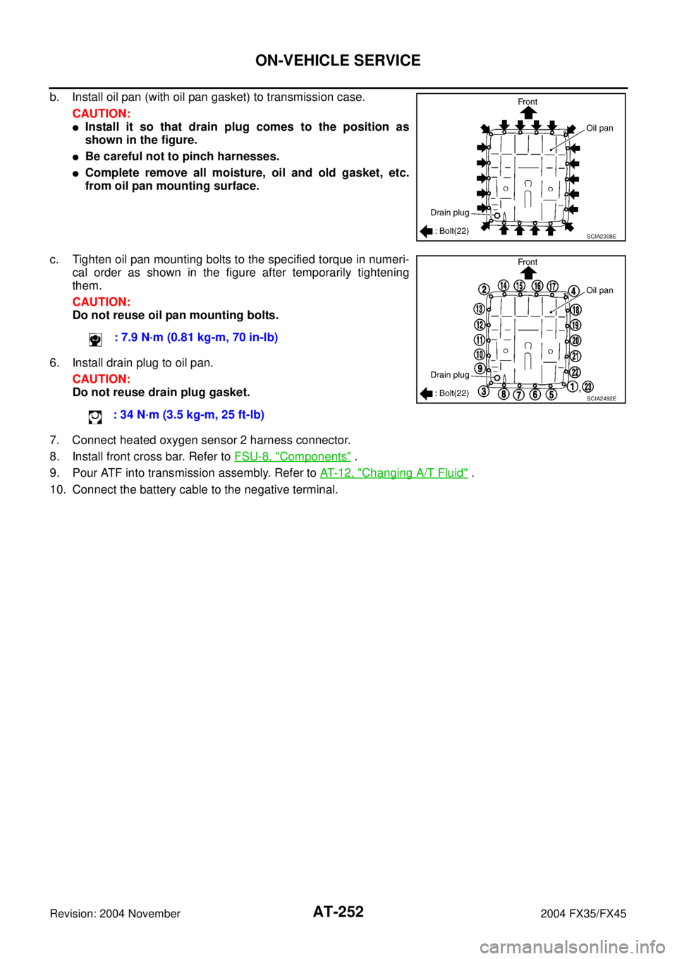
b. Install oil pan (with oil pan gasket) to transmission case.
CAUTION:
�Install it so that drain plug comes to the position as
shown in the figure.
�Be careful not to pinch harnesses.
�Complete remove all moisture, oil and old gasket, etc.
from oil pan mounting surface.
c. Tighten oil pan mounting bolts to the specified torque in numeri-
cal order as shown in the figure after temporarily tightening
them.
CAUTION:
Do not reuse oil pan mounting bolts.
6. Install drain plug to oil pan.
CAUTION:
Do not reuse drain plug gasket.
7. Connect heated oxygen sensor 2 harness connector.
8. Install front cross bar. Refer to FSU-8, "
Components" .
9. Pour ATF into transmission assembly. Refer to AT- 1 2 , "
Changing A/T Fluid" .
10. Connect the battery cable to the negative terminal.
SCIA2308E
: 7.9 N·m (0.81 kg-m, 70 in-lb)
: 34 N·m (3.5 kg-m, 25 ft-lb)
SCIA2492E