Page 960 of 4449
FRONT DOOR LOCK
BL-153
C
D
E
F
G
H
J
K
L
MA
B
BL
Revision: 2004 November 2004 FX35/FX45
CAUTION:
Do not forcibly remove the TORX bolt (T30).
5. Reach to separate the key cylinder rod connection (on the handle).
6. While pulling the outside handle, remove door key cylinder
assembly (driver side) and outside handle escutcheon (passen-
ger side).
7. Disconnect the door request switch connector. (intelligent key only)
8. While pulling outside handle, slide toward rear of vehicle to
remove outside handle.
9. Remove the front gasket and rear gasket.
PIIA3553E
PIIA3554E
PIIA3555E
PIIA3557E
Page 963 of 4449
BL-156
REAR DOOR LOCK
Revision: 2004 November 2004 FX35/FX45
REAR DOOR LOCKPFP:82502
Removal and InstallationAIS004O2
REMOVAL
1. Remove the rear door finisher. Refer to EI-35, "Removal and Installation" .
2. Disconnect the inside handle knob cable and lock knob cable
from the back side of the front door finisher.
3. Remove the rear door sealing, glass and corner piece assembly. Refer to GW-80, "
Removal and Installa-
tion" .
4. Remove door side grommet, and remove outside handle escutcheon bolt (TORX T30) from grommet
hole.
1. Front gasket 2. Outside handle 3. Outside handle escutcheon
4. Rear gasket 5. Outside handle bracket 6. Grommet
7. TORX bolt (T30) 8. Outside handle cable 9. TORX bolts (T30)
10. Door lock assembly 11. Inside handle knob cable 12. Lock knob cable
13. Screw 14. Inside handle
PIIA6027E
PIIA4014E
Page 964 of 4449
REAR DOOR LOCK
BL-157
C
D
E
F
G
H
J
K
L
MA
B
BL
Revision: 2004 November 2004 FX35/FX45
CAUTION:
Do not forcibly remove the TORX bolt (T30).
5. While pulling the outside handle, remove outside handle
escutcheon.
6. While pulling outside handle, slide toward rear of vehicle to
remove outside handle.
7. Remove the front gasket and rear gasket.
PIIA3553E
PIIA6344E
PIIA3555E
PIIA3557E
Page 1062 of 4449

BODY REPAIR
BL-255
C
D
E
F
G
H
J
K
L
MA
B
BL
Revision: 2004 November2004 FX35/FX45
Handling Precautions For PlasticsAIS00628
HANDLING PRECAUTIONS FOR PLASTICS
1. When repairing and painting a portion of the body adjacent to plastic parts, consider their characteristics
(influence of heat and solvent) and remove them if necessary or take suitable measures to protect them.
2. Plastic parts should be repaired and painted using methods suiting the materials
,characteristics.
Abbre-
viationMaterial nameHeat
resisting
temperature
°C(°F)Resistance to gasoline and
solventsOther cautions
PE Polyethylene 60(140)Gasoline and most solvents are
harmless if applied for a very
short time (wipe up quickly).Flammable
PVC Poly Vinyl Chloride 80(176) Same as above.Poison gas is emitted
when burned.
EPM/
EPDMEthylene Propylene (Diene)
copolymer80(176) Same as above. Flammable
PP Polypropylene 90(194) Same as above.Flammable, avoid
battery acid.
UP Unsaturated Polyester 90(194) Same as above. Flammable
PS Polystyrene 80(176) Avoid solvents. Flammable
ABS Acrylonitrile Butadiene Styrene 80(176) Avoid gasoline and solvents.
AES Acrylonitrile Ethylene Styrene 80(176) Same as above.
PMMA Poly Methyl Methacrylate 85(185) Same as above.
EVAC Ethylene Vinyl Acetate 90(194) Same as above.
ASA Acrylonitrile Styrene Acrylate 100(222) Same as above. Flammable
PPE Poly Phenylene Ether 110(230) Same as above.
PC Polycarbonate 120(248) Same as above.
PAR Polyarylate 180(356) Same as above.
PUR Polyurethane 90(194) Same as above.
POM Poly Oxymethylene 120(248) Same as above. Avoid battery acid.
PBT+
PCPoly Butylene Terephthalate +
Polycarbonate120(248) Same as above. Flammable
PA Polyamide 140(284) Same as above.Avoid immersing in
water.
PBT Poly Butylene Terephthalate 140(284) Same as above.
PET Polyester 180(356) Same as above.
PEI Polyetherimide 200(392) Same as above.
Page 1066 of 4449

BODY REPAIR
BL-259
C
D
E
F
G
H
J
K
L
MA
B
BL
Revision: 2004 November2004 FX35/FX45
Read the Following Precautions When Repairing HSS:
1. Additional points to consider
lThe repair of reinforcements (such as side members) by heat-
ing is not recommended since it may weaken the component.
When heating is unavoidable, do not heat HSS parts above
550°C (1,022°F).
Verify heating temperature with a thermometer.
(Crayon-type and other similar type thermometer are appro-
priate.)
lWhen straightening body panels, use caution in pulling any
HSS panel. Because HSS is very strong, pulling may cause
deformation in adjacent portions of the body. In this case,
increase the number of measuring points, and carefully pull
the HSS panel.
lWhen cutting HSS panels, avoid gas (torch) cutting if possi-
ble. Instead, use a saw to avoid weakening surrounding areas
due to heat. If gas (torch) cutting is unavoidable, allow a mini-
mum margin of 50 mm (1.97in).
lWhen welding HSS panels, use spot welding whenever possi-
ble in order to minimize weakening surrounding areas due to
heat.
If spot welding is impossible, use M.I.G. welding. Do not use
gas (torch) welding because it is inferior in welding strength.
PIIA0115E
PIIA0116E
PIIA0117E
PIIA0144E
Page 1096 of 4449
 “AIR BAG” and “SEAT
BELT PRE-TENSIONER")
PRECAUTIONS
BR-3
C
D
E
G
H
I
J
K
L
MA
B
BR
Revision: 2004 November 2004 FX35/FX45
PRECAUTIONSPFP:00001
Precautions for Supplemental Restraint System (SRS) “AIR BAG” and “SEAT
BELT PRE-TENSIONER”
AFS0028A
The Supplemental Restraint System such as “AIR BAG” and “SEAT BELT PRE-TENSIONER”, used along
with a front seat belt, helps to reduce the risk or severity of injury to the driver and front passenger for certain
types of collision. This system includes seat belt switch inputs and dual stage front air bag modules. The SRS
system uses the seat belt switches to determine the front air bag deployment, and may only deploy one front
air bag, depending on the severity of a collision and whether the front occupants are belted or unbelted.
Information necessary to service the system safely is included in the SRS and SB section of this Service Man-
ual.
WARNING:
�To avoid rendering the SRS inoperative, which could increase the risk of personal injury or death
in the event of a collision which would result in air bag inflation, all maintenance must be per-
formed by an authorized NISSAN/INFINITI dealer.
�Improper maintenance, including incorrect removal and installation of the SRS, can lead to per-
sonal injury caused by unintentional activation of the system. For removal of Spiral Cable and Air
Bag Module, see the SRS section.
�Do not use electrical test equipment on any circuit related to the SRS unless instructed to in this
Service Manual. SRS wiring harnesses can be identified by yellow and/or orange harnesses or
harness connectors.
Precautions for Brake SystemAFS001MQ
�Recommended fluid is brake fluid “DOT 3”.
�Do not reuse drained brake fluid.
�Be careful not to splash brake fluid on painted areas.
�To clean or wash all parts of master cylinder, disc brake caliper and wheel cylinder, use clean brake fluid.
�Do not use mineral oils such as gasoline or kerosene. They will ruin rubber parts of the hydraulic system.
�Use flare nut wrench when removing and installing brake tube.
�When installing brake piping, be sure to check torque.
�Before working, turn ignition switch OFF and disconnect con-
nectors for ABS actuator and electric unit (control unit) or battery
terminal.
�Burnish the brake contact surfaces after refinishing or replacing
drums or rotors, after replacing pads or linings, or if a soft pedal
occurs at very low mileage.
Refer to BR-24, "
BRAKE BURNISHING PROCEDURE" .
WARNING:
�Clean brake pads and shoes with a waste cloth, then wipe
with a dust collector.SBR686C
Page 1107 of 4449
BR-14
BRAKE MASTER CYLINDER
Revision: 2004 November 2004 FX35/FX45
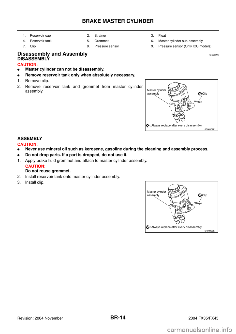
Disassembly and AssemblyAFS001N5
DISASSEMBLY
CAUTION:
�Master cylinder can not be disassembly.
�Remove reservoir tank only when absolutely necessary.
1. Remove clip.
2. Remove reservoir tank and grommet from master cylinder
assembly.
ASSEMBLY
CAUTION:
�Never use mineral oil such as kerosene, gasoline during the cleaning and assembly process.
�Do not drop parts. If a part is dropped, do not use it.
1. Apply brake fluid grommet and attach to master cylinder assembly.
CAUTION:
Do not reuse grommet.
2. Install reservoir tank onto master cylinder assembly.
3. Install clip.
1. Reservoir cap 2. Strainer 3. Float
4. Reservoir tank 5. Grommet 6. Master cylinder sub-assembly
7. Clip 8. Pressure sensor 9. Pressure sensor (Only ICC models)
SFIA1132E
SFIA1132E
Page 1109 of 4449

BR-16
BRAKE BOOSTER
Revision: 2004 November 2004 FX35/FX45
Removal and InstallationAFS001N7
REMOVAL
CAUTION:
�Be careful not to deform or bend brake piping while removing and installing brake booster.
�Replace clevis pin if it is damaged.
�Be careful not to damage brake booster stud bolt threads. If brake booster is tilted or inclined dur-
ing installation, dash panel may damage the threads.
�Attach the check valve in the correct direction.
1. Remove brake piping from brake master cylinder.
2. Remove brake master cylinder. Refer to BR-13, "
Removal and Installation" .
3. Remove vacuum hose from brake booster. Refer to BR-18, "
VACUUM LINES" .
4. Disconnect harness connector from brake booster assembly. (ICC model)
5. Remove brake pedal attachment snap pin and clevis pin from inside the vehicle.
6. Remove nuts on brake booster and brake pedal assembly.
7. Remove brake booster assembly from dash panel.
INSPECTION AFTER REMOVAL
Output Rod Length Inspection
1. Using a handy vacuum pump, apply a vacuum of – 66.7 kPa (–
500 mmHg, –19.69 inHg) to brake booster.
2. Check output rod length.
1. Reservoir tank 2. Master cylinder 3. Gasket
4. Brake pedal 5. Lock nut 6. Brake booster
SFIA1033E
Standard dimension when vacuum
-66.7kpa (500mmHg, -19.69inHg):
15.6 − 15.9 mm (0.614 − 0.626 in)
SFIA2146E
.
5. Reach to separate the key cylinder rod connection (on th")

.
5. While pulling the outside handle, remove outside handle
e")