Page 4213 of 4449
SE-84
AUTOMATIC DRIVE POSITIONER
Revision: 2004 November 2004 FX35/FX45
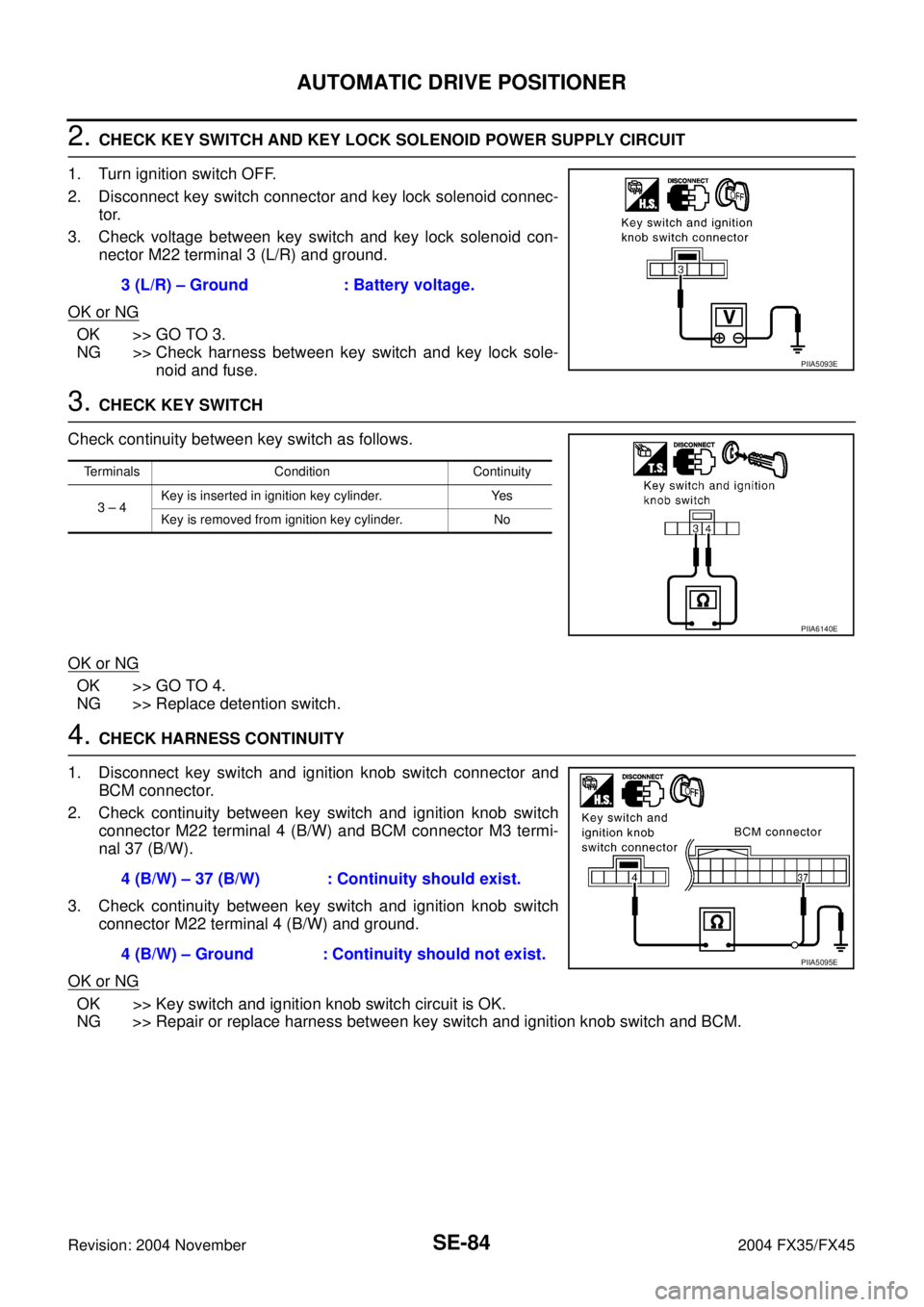
2. CHECK KEY SWITCH AND KEY LOCK SOLENOID POWER SUPPLY CIRCUIT
1. Turn ignition switch OFF.
2. Disconnect key switch connector and key lock solenoid connec-
tor.
3. Check voltage between key switch and key lock solenoid con-
nector M22 terminal 3 (L/R) and ground.
OK or NG
OK >> GO TO 3.
NG >> Check harness between key switch and key lock sole-
noid and fuse.
3. CHECK KEY SWITCH
Check continuity between key switch as follows.
OK or NG
OK >> GO TO 4.
NG >> Replace detention switch.
4. CHECK HARNESS CONTINUITY
1. Disconnect key switch and ignition knob switch connector and
BCM connector.
2. Check continuity between key switch and ignition knob switch
connector M22 terminal 4 (B/W) and BCM connector M3 termi-
nal 37 (B/W).
3. Check continuity between key switch and ignition knob switch
connector M22 terminal 4 (B/W) and ground.
OK or NG
OK >> Key switch and ignition knob switch circuit is OK.
NG >> Repair or replace harness between key switch and ignition knob switch and BCM.3 (L/R) – Ground : Battery voltage.
PIIA5093E
Terminals Condition Continuity
3 – 4Key is inserted in ignition key cylinder. Yes
Key is removed from ignition key cylinder. No
PIIA6140E
4 (B/W) – 37 (B/W) : Continuity should exist.
4 (B/W) – Ground : Continuity should not exist.
PIIA5095E
Page 4214 of 4449
AUTOMATIC DRIVE POSITIONER
SE-85
C
D
E
F
G
H
J
K
L
MA
B
SE
Revision: 2004 November 2004 FX35/FX45
Key Switch Circuit Check (Without Intelligent Key)AIS003G1
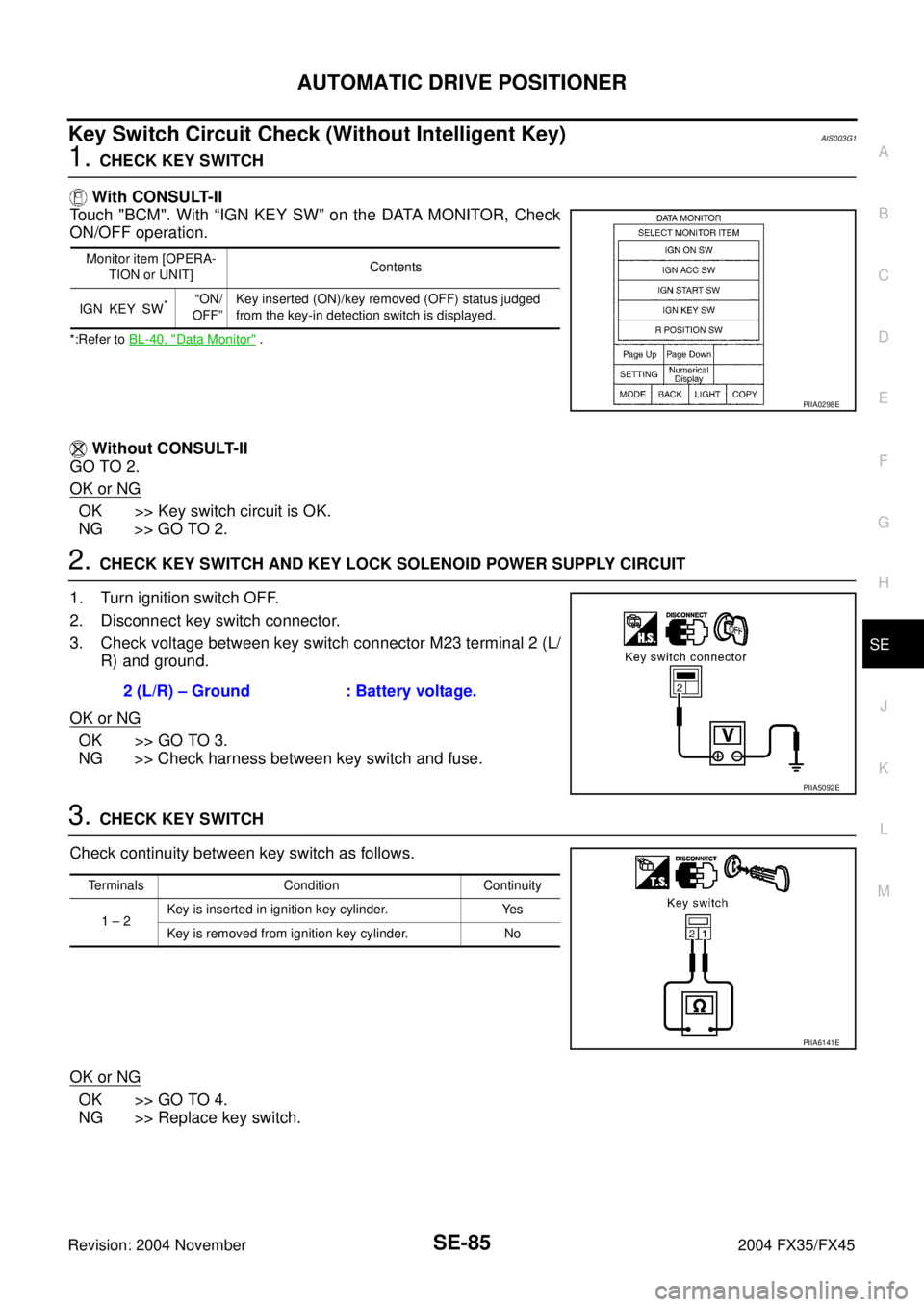
1. CHECK KEY SWITCH
With CONSULT-II
Touch "BCM". With “IGN KEY SW” on the DATA MONITOR, Check
ON/OFF operation.
*:Refer to BL-40, "Data Monitor" .
Without CONSULT-II
GO TO 2.
OK or NG
OK >> Key switch circuit is OK.
NG >> GO TO 2.
2. CHECK KEY SWITCH AND KEY LOCK SOLENOID POWER SUPPLY CIRCUIT
1. Turn ignition switch OFF.
2. Disconnect key switch connector.
3. Check voltage between key switch connector M23 terminal 2 (L/
R) and ground.
OK or NG
OK >> GO TO 3.
NG >> Check harness between key switch and fuse.
3. CHECK KEY SWITCH
Check continuity between key switch as follows.
OK or NG
OK >> GO TO 4.
NG >> Replace key switch.
Monitor item [OPERA-
TION or UNIT]Contents
IGN KEY SW
*“ON/
OFF”Key inserted (ON)/key removed (OFF) status judged
from the key-in detection switch is displayed.
PIIA0298E
2 (L/R) – Ground : Battery voltage.
PIIA5092E
Terminals Condition Continuity
1 – 2Key is inserted in ignition key cylinder. Yes
Key is removed from ignition key cylinder. No
PIIA6141E
Page 4217 of 4449
SE-88
AUTOMATIC DRIVE POSITIONER
Revision: 2004 November 2004 FX35/FX45
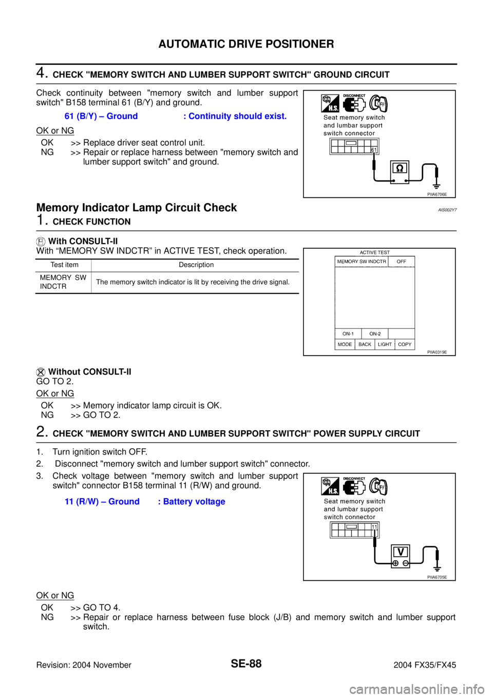
4. CHECK "MEMORY SWITCH AND LUMBER SUPPORT SWITCH" GROUND CIRCUIT
Check continuity between "memory switch and lumber support
switch" B158 terminal 61 (B/Y) and ground.
OK or NG
OK >> Replace driver seat control unit.
NG >> Repair or replace harness between "memory switch and
lumber support switch" and ground.
Memory Indicator Lamp Circuit CheckAIS002Y7
1. CHECK FUNCTION
With CONSULT-II
With “MEMORY SW INDCTR” in ACTIVE TEST, check operation.
Without CONSULT-II
GO TO 2.
OK or NG
OK >> Memory indicator lamp circuit is OK.
NG >> GO TO 2.
2. CHECK "MEMORY SWITCH AND LUMBER SUPPORT SWITCH" POWER SUPPLY CIRCUIT
1. Turn ignition switch OFF.
2. Disconnect "memory switch and lumber support switch" connector.
3. Check voltage between "memory switch and lumber support
switch" connector B158 terminal 11 (R/W) and ground.
OK or NG
OK >> GO TO 4.
NG >> Repair or replace harness between fuse block (J/B) and memory switch and lumber support
switch. 61 (B/Y) – Ground : Continuity should exist.
PIIA6706E
Test item Description
MEMORY SW
INDCTRThe memory switch indicator is lit by receiving the drive signal.
PIIA0319E
11 (R/W) – Ground : Battery voltage
PIIA6705E
Page 4220 of 4449
AUTOMATIC DRIVE POSITIONER
SE-91
C
D
E
F
G
H
J
K
L
MA
B
SE
Revision: 2004 November 2004 FX35/FX45
Lumber Support Circuit CheckAIS003C1
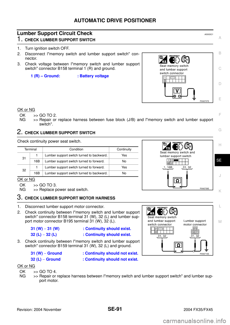
1. CHECK LUMBER SUPPORT SWITCH
1. Turn ignition switch OFF.
2. Disconnect l"memory switch and lumber support switch" con-
nector.
3. Check voltage between l"memory switch and lumber support
switch" connector B158 terminal 1 (R) and ground.
OK or NG
OK >> GO TO 2.
NG >> Repair or replace harness between fuse block (J/B) and l"memory switch and lumber support
switch".
2. CHECK LUMBER SUPPORT SWITCH
Check continuity power seat switch.
OK or NG
OK >> GO TO 3.
NG >> Replace power seat switch.
3. CHECK LUMBER SUPPORT MOTOR HARNESS
1. Disconnect lumber support motor connector.
2. Check continuity between l"memory switch and lumber support
switch" connector B158 terminal 31 (W), 32 (L) and lumber sup-
port motor connector B195 terminal 31 (W), 32 (L).
3. Check continuity between l"memory switch and lumber support
switch" connector B159 terminal 31 (W), 32 (L) and ground.
OK or NG
OK >> GO TO 4.
NG >> Repair or replace harness between l"memory switch and lumber support switch" and lumber sup-
port motor. 1 (R) – Ground: : Battery voltage
PIIA6707E
Terminal Condition Continuity
311 Lumber support switch turned to backward. Yes
16B Lumber support switch turned to forward. No
321 Lumber support switch turned to forward. Yes
16B Lumber support switch turned to backward. No
PIIA6709E
31 (W) − 31 (W) : Continuity should exist.
32 (L) − 32 (L) : Continuity should exist.
31 (W) − Ground : Continuity should not exist.
32 (L) − Ground : Continuity should not exist.
PIIA6710E
Page 4222 of 4449
POWER SEAT
SE-93
C
D
E
F
G
H
J
K
L
MA
B
SE
Revision: 2004 November 2004 FX35/FX45
POWER SEATPFP:87016
Automatic Drive Positioner Interlocking Power SeatAIS003L4
A trouble diagnosis of a automatic drive positioner interlocking power seat is refer toSE-11, "AUTOMATIC
DRIVE POSITIONER" .
Page 4238 of 4449
REAR SEAT
SE-109
C
D
E
F
G
H
J
K
L
MA
B
SE
Revision: 2004 November 2004 FX35/FX45
REMOVAL
1. Pull the lock at the front bottom of the seat cushion forward (1
for each side), and pull the seat cushion upward to release the
wire from the plastic hook, then pull the seat cushion forward to
remove.
2. Remove the seatback mounting nuts.
3. Remove the seatback mounting bolt and nut.
Remove the remote control wire.
INSTALLATION
Install in the reverse order of removal.
NOTE:
After rear wheel house finisher assembly is remove the seatback is installed. Refer to EI-44, "
Removal and
Installation" .
REMOVAL OF SEAT CUSHION TRIM AND PAD
1. Remove the cup holder in the back of the seat cushion.
2. Removal the hog rings to separate the trim and pad.
PIIA6034E
PIIA6035E
PIIA6036E
PIIA4985E
Page 4275 of 4449
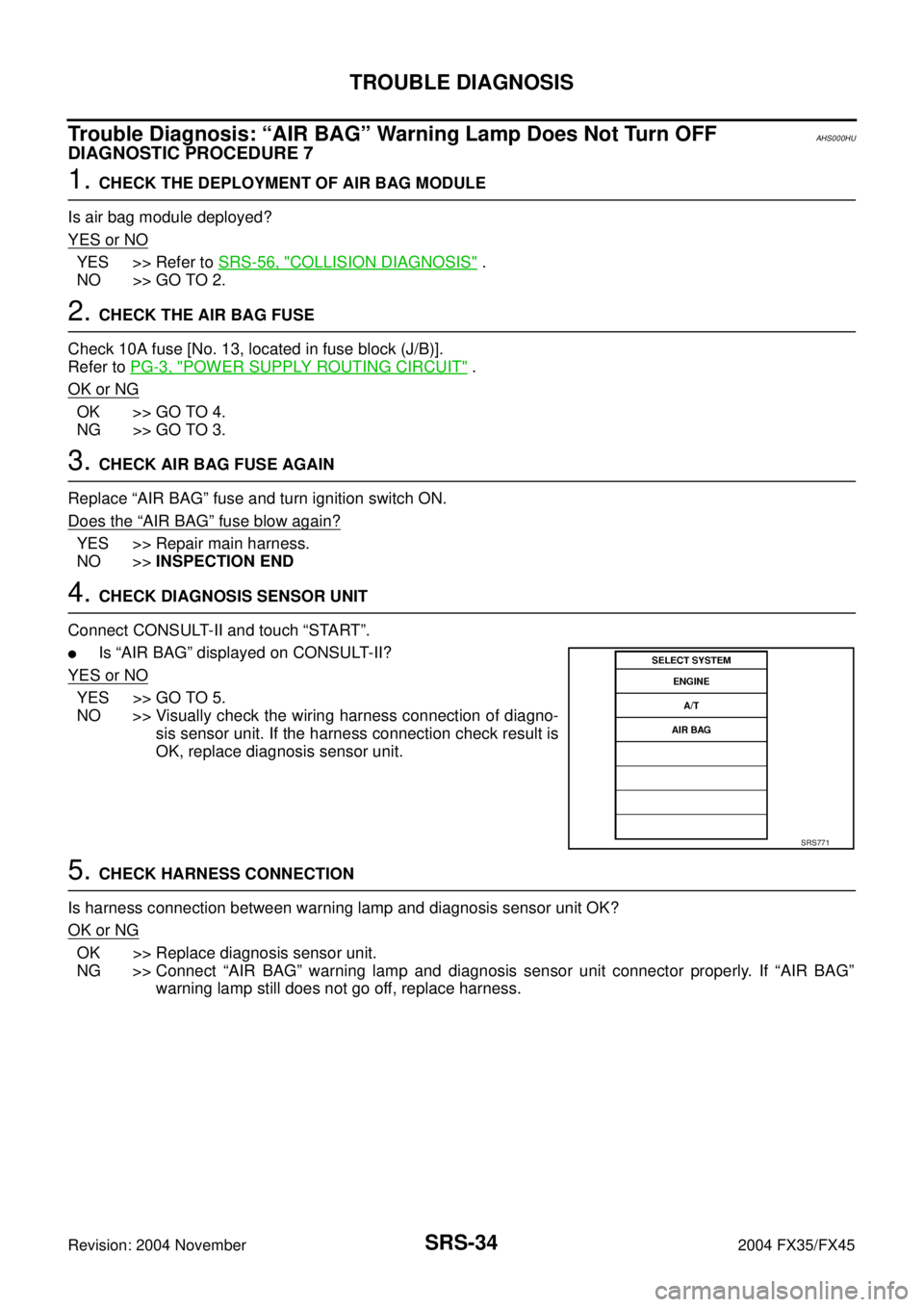
SRS-34
TROUBLE DIAGNOSIS
Revision: 2004 November 2004 FX35/FX45
Trouble Diagnosis: “AIR BAG” Warning Lamp Does Not Turn OFFAHS000HU
DIAGNOSTIC PROCEDURE 7
1. CHECK THE DEPLOYMENT OF AIR BAG MODULE
Is air bag module deployed?
YES or NO
YES >> Refer to SRS-56, "COLLISION DIAGNOSIS" .
NO >> GO TO 2.
2. CHECK THE AIR BAG FUSE
Check 10A fuse [No. 13, located in fuse block (J/B)].
Refer to PG-3, "
POWER SUPPLY ROUTING CIRCUIT" .
OK or NG
OK >> GO TO 4.
NG >> GO TO 3.
3. CHECK AIR BAG FUSE AGAIN
Replace “AIR BAG” fuse and turn ignition switch ON.
Does the
“AIR BAG” fuse blow again?
YES >> Repair main harness.
NO >>INSPECTION END
4. CHECK DIAGNOSIS SENSOR UNIT
Connect CONSULT-II and touch “START”.
�Is “AIR BAG” displayed on CONSULT-II?
YES or NO
YES >> GO TO 5.
NO >> Visually check the wiring harness connection of diagno-
sis sensor unit. If the harness connection check result is
OK, replace diagnosis sensor unit.
5. CHECK HARNESS CONNECTION
Is harness connection between warning lamp and diagnosis sensor unit OK?
OK or NG
OK >> Replace diagnosis sensor unit.
NG >> Connect “AIR BAG” warning lamp and diagnosis sensor unit connector properly. If “AIR BAG”
warning lamp still does not go off, replace harness.
SRS771
Page 4276 of 4449
TROUBLE DIAGNOSIS
SRS-35
C
D
E
F
G
I
J
K
L
MA
B
SRS
Revision: 2004 November 2004 FX35/FX45
Trouble Diagnosis: “AIR BAG” Warning Lamp Does Not Turn ONAHS000HV
DIAGNOSTIC PROCEDURE 8
1. CHECK METER FUSE
Check 10A fuse [No. 14, located in fuse block (J/B)].
Refer to PG-3, "
POWER SUPPLY ROUTING CIRCUIT" .
OK or NG
OK >> GO TO 3.
NG >> GO TO 2.
2. CHECK METER FUSE AGAIN
Replace 10A fuse [No. 14, located in fuse block (J/B)] and turn ignition switch ON.
Does the meter fuse blow again?
YES >> Repair the related harness.
NO >>INSPECTION END
3. CHECK HARNESS CONNECTION BETWEEN DIAGNOSIS SENSOR UNIT AND COMBINATION
METER
Disconnect diagnosis sensor unit connector and turn ignition switch ON.
�Does “AIR BAG” warning lamp turn ON?
YES or NO
YES >> Replace diagnosis sensor unit.
NO >> Check the ground circuit of “AIR BAG” warning lamp.