Page 4068 of 4449

SHOCK ABSORBER
RSU-9
C
D
F
G
H
I
J
K
L
MA
B
RSU
Revision: 2004 November 2004 FX35/FX45
SHOCK ABSORBERPFP:56210
Removal and InstallationAES000MN
REMOVAL
1. Remove tire with power tool.
2. Set jack under rear lower link.
3. Remove fixing bolt in lower side of shock absorber assembly with power tool.
4. Remove fixing nuts in upper side of shock absorber assembly
with power tool and remove shock absorber assembly from
vehicle.
INSPECTION AFTER REMOVAL
�Check shock absorber assembly for deformation, cracks, or damage, and replace if necessary.
�Check piston rod for damage, uneven wear, or distortion, and replace if necessary.
�Check welded and sealed areas for oil leakage, and replace if necessary.
INSTALLATION
�Refer to RSU-7, "Components" for tightening torque. Install in the reverse order of removal.
NOTE:
Refer to component parts location and do not reuse non-reusable parts.
�Perform final tightening of shock absorber assembly lower side (rubber bushing) under unladen condi-
tions with tires on level ground. Check wheel alignment. Refer to RSU-5, "
Wheel Alignment Inspection" .
�After adjusting wheel alignment, adjust neutral position of steering angle sensor. Refer to BRC-6, "Adjust-
ment of Steering Angle Sensor Neutral Position" .
Disassembly and AssemblyAES000MO
DISASSEMBLY
CAUTION:
Make sure piston rod on shock absorber is not damaged when removing components from shock
absorber.
1. Remove mounting seal from mounting seal bracket.
2. Wrap a shop cloth around lower side of shock absorber and fix it in a vise.
CAUTION:
Do not set the cylindrical part of shock absorber in vise.
3. Fix piston rod with hexagon wrench, and remove piston rod lock
nut.
4. Remove mounting seal bracket, bushing, distance tube, bound
bumper cover and bound bumper from shock absorber.
FA-0274D
SEIA0366E
Page 4082 of 4449

SEAT BELTS
SB-5
C
D
E
F
G
I
J
K
L
MA
B
SB
Revision: 2004 November 2004 FX35/FX45
REMOVAL OF FRONT SEAT BELT RETRACTOR
1. Remove the adjuster cover on the through anchor.
2. Remove the anchor bolt.
3. Remove the seat cushion outer finisher cover, and remove the anchor bolt.
NOTE:
Set the front and rear cushion lifter to the down position.
4. Remove the center pillar upper and lower garnish. Refer to EI-37, "
Removal and Installation" .
5. Disconnect the seat belt pre-tensioner connector.
CAUTION:
�For installing/removing seat belt pre-tensioner connector,
insert thin screwdriver wrapped in tape into notch, lift lock
and remove connector.
�Install connector with lock raised, and push lock into con-
nector.
6. Remove the seat belt pre-tensioner retractor fixing screw and anchor bolt, and then remove the seat belt
retractor.
INSTALLATION OF FRONT SEAT BELT RETRACTOR
CAUTION:
Before servicing SRS, turn ignition switch OFF, disconnect both battery cables and wait at least 3 min-
utes.
Install in the reverse order of removal.
REMOVAL OF FRONT SEAT BELT BUCKLE
1. Remove the front seat. Refer to SE-101, "Removal and Installa-
tion" .
2. Disconnect the buckle switch connector.
3. Remove the anchor bolt, and remove the buckle.
INSTALLATION OF FRONT SEAT BELT BUCKLE
Install in the reverse order of removal.
PHIA0341E
PHIA0346E
Page 4086 of 4449
 and Automatic Locking Retractors (ALR)
NOT")
SEAT BELTS
SB-9
C
D
E
F
G
I
J
K
L
MA
B
SB
Revision: 2004 November 2004 FX35/FX45
SEAT BELT RETRACTOR ON-VEHICLE INSPECTION
Emergency Locking Retractors (ELR) and Automatic Locking Retractors (ALR)
NOTE:
All seat belt retractors are of the Emergency Locking Retractors (ELR) type. In an emergency (sudden stop)
the retractor will lock and prevent the webbing from extending any further. All 3-point type seat belt retractors
except the driver's seat belt also have an Automatic Locking Retractors (ALR) mode. The ALR mode (also
called child restraint mode) is used when installing child seats. The ALR mode is activated when the seat belt
is fully extended. When the webbing is then retracted partially, the ALR mode automatically locks the seat belt
in a specific position so the webbing cannot be extended any further. To cancel the ALR mode, allow the seat
belt to fully wind back into the retractor.
Check the seat belt retractors using the following test(s) to determine if a retractor assembly is operating prop-
erly.
Stationary Inspection for ELR Function
Grasp the shoulder webbing and pull forward quickly. The retractor should lock and prevent the belt from
extending further.
Stationary Inspection for ALR Function
1. Pull out entire length of seat belt from retractor until a click is heard.
2. Retract the webbing partially. A clicking noise should be heard as the webbing retracts indicating that the
retractor is in the Automatic Locking Retractor (ALR) mode.
3. Grasp the seat belt and try to pull out the retractor. The webbing must lock and not extend any further. If
necessary replace the retractor assembly.
4. Allow the entire length of the webbing to retract to cancel the automatic locking mode.
Moving Inspection for ELR Function
WARNING:
Perform the following test in a safe, open area clear of other vehicles and obstructions (for example, a
large, empty parking lot). Road surface must be paved and dry. DO NOT perform the following test on
wet or gravel roads or on public streets and highways. This could result in an accident and serious
personal injury. The driver and passenger must be prepared to brace themselves in the event the
retractor does not lock.
1. Fasten driver's seat belt. Buckle a passenger into the seat for the belt that is to be tested.
2. Proceed to the designated safe area.
3. Drive the vehicle at approximately 16 km/h (10 MPH). Notify any passengers of a pending sudden stop.
The driver and passenger must be prepared to brace themselves in the event the retractor does not lock.
Apply brakes firmly and make a very hard stop.
During stop, seat belts should lock and not be extended. If the seat belt retractor assembly does not lock, per-
form the retractor off-vehicle inspection.
Page 4087 of 4449
SB-10
SEAT BELTS
Revision: 2004 November 2004 FX35/FX45
SEAT BELT RETRACTOR OFF-VEHICLE INSPECTION
1. Remove the seat belt retractor assembly.
2. Slowly pull out webbing while tilting the retractor assembly forward from the mounted position without
twisting the retractor assembly as shown in the figure.
If NG, replace the retractor assembly.15 degrees or less tilt : Webbing can be pulled out.
35 degrees or more tilt : Webbing locks and cannot be pulled out.
PHIA0257E
Page 4099 of 4449

SC-10
STARTING SYSTEM
Revision: 2004 November 2004 FX35/FX45
STARTING SYSTEMPFP:23300
System Description AKS0079C
Power is supplied at all times:
�through 40A fusible link (letter F, located in the fuse and fusible link box)
�to ignition switch terminal 1
�through 15A fuse (No. 78, located in the IPDM E/R)
�to CPU of IPDM E/R
�through 10A fuse (No. 71, located in the IPDM E/R)
�to CPU of IPDM E/R.
When the selector lever in the P or N position, power is supplied:
�from TCM, and through A/T assembly terminal 9
�to IPDM E/R terminal 53.
Ground is supplied:
�to IPDM E/R terminals 38, 50 and 60
�from body grounds E21, E50 and E51.
With the ignition switch in the START position, and provided that the IPDM E/R receives a starter relay ON sig-
nal from the CAN lines, the IPDM E/R is energized and power is supplied:
�from ignition switch terminal 5
�to IPDM E/R terminal 4 and
�through IPDM E/R terminal 3
�to starter motor terminal 1.
The starter motor plunger closes and provides a closed circuit between the battery and starter motor. The
starter motor is grounded to the engine block. With power and ground supplied, cranking occurs and the
engine starts.
Page 4106 of 4449
STARTING SYSTEM
SC-17
C
D
E
F
G
H
I
J
L
MA
B
SC
Revision: 2004 November 2004 FX35/FX45
Removal and Installation AKS00BQ1
VK45DE ENGINE MODELS
Removal
1. Disconnect negative battery cable.
2. Remove engine front and rear undercover, using power tools.
3. Disconnect S connector.
4. Remove B terminal nut.
5. Remove starter motor mounting bolts.
6. Loosen A/T fluid cooler tube clip bolts. Refer to AT- 2 6 6 ,
"TRANSMISSION ASSEMBLY" in “AUTOMATIC TRANSMIS-
SION (A/T)” section.
7. Remove starter motor to the direction of under side the vehicle.
Installation
Install in the reverse order of removal.
CAUTION:
Be sure to tighten B terminal nut carefully.
1. Starter motor 2. Starter motor mounting bolt 3. B terminal harness
4. B terminal nut 5. S connector 6. Cylinder block
PKIA2809E
PKIA2810E
Page 4111 of 4449
SC-22
STARTING SYSTEM
Revision: 2004 November 2004 FX35/FX45
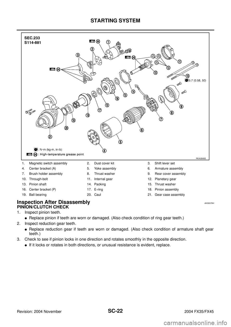
Inspection After Disassembly AKS0079H
PINION/CLUTCH CHECK
1. Inspect pinion teeth.
�Replace pinion if teeth are worn or damaged. (Also check condition of ring gear teeth.)
2. Inspect reduction gear teeth.
�Replace reduction gear if teeth are worn or damaged. (Also check condition of armature shaft gear
teeth.)
3. Check to see if pinion locks in one direction and rotates smoothly in the opposite direction.
�If it locks or rotates in both directions, or unusual resistance is evident, replace.
1. Magnetic switch assembly 2. Dust cover kit 3. Shift lever set
4. Center bracket (A) 5. Yoke assembly 6. Armature assembly
7. Brush holder assembly 8. Thrust washer 9. Rear cover assembly
10. Through-bolt 11. Internal gear 12. Planetary gear
13. Pinion shaft 14. Packing 15. Thrust washer
16. Center bracket (P) 17. E-ring 18. Pinion assembly
19. Ball bearing 20. Caul 21. Gear case assembly
PKIA2845E
Page 4112 of 4449

CHARGING SYSTEM
SC-23
C
D
E
F
G
H
I
J
L
MA
B
SC
Revision: 2004 November 2004 FX35/FX45
CHARGING SYSTEMPFP:23100
System DescriptionAKS0079I
The alternator provides DC voltage to operate the vehicle's electrical system and to keep the battery charged.
The voltage output is controlled by the IC regulator.
Power is supplied at all times:
�through 10A fuse (No. 33, located in the fuse and fusible link box)
�to alternator terminal 4 (S).
Terminal B supplies power to charge the battery and operate the vehicle's electrical system. Output voltage is
controlled by the IC regulator at terminal 4 (S) detecting the input voltage.
The charging circuit is protected by the 120A fusible link (VK45DE and VQ35DE AWD).
The alternator is grounded to the engine block.
With the ignition switch in the ON or START position, power is supplied:
�through 10A fuse [No. 14, located in the fuse block (J/B)]
�to combination meter terminal 7 for the charge warning lamp.
Ground is supplied:
�to combination meter terminal 2
�through alternator terminal 3 (L)
�to alternator terminal E (VK45DE) or through body ground (VQ35DE)
�through body ground E304 (VK45DE).
With power and ground supplied, the charge warning lamp will illuminate. When the alternator is providing suf-
ficient voltage with the engine running, the ground is opened and the charge warning lamp will go off.
If the charge warning lamp illuminates with the engine running, a malfunction is indicated.