Page 4040 of 4449
REAR FINAL DRIVE ASSEMBLY
RFD-13
C
E
F
G
H
I
J
K
L
MA
B
RFD
Revision: 2004 November 2004 FX35/FX45
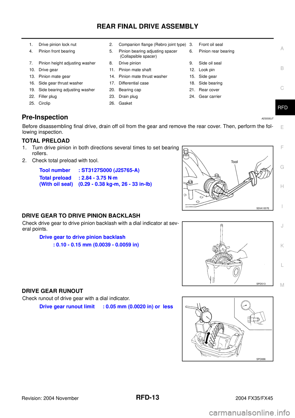
Pre-InspectionADS000JT
Before disassembling final drive, drain off oil from the gear and remove the rear cover. Then, perform the fol-
lowing inspection.
TOTAL PRELOAD
1. Turn drive pinion in both directions several times to set bearing
rollers.
2. Check total preload with tool.
DRIVE GEAR TO DRIVE PINION BACKLASH
Check drive gear to drive pinion backlash with a dial indicator at sev-
eral points.
DRIVE GEAR RUNOUT
Check runout of drive gear with a dial indicator.
1. Drive pinion lock nut 2. Companion flange (Rebro joint type) 3. Front oil seal
4. Pinion front bearing 5. Pinion bearing adjusting spacer
(Collapsible spacer)6. Pinion rear bearing
7. Pinion height adjusting washer 8. Drive pinion 9. Side oil seal
10. Drive gear 11. Pinion mate shaft 12. Look pin
13. Pinion mate gear 14. Pinion mate thrust washer 15. Side gear
16. Side gear thrust washer 17. Differential case 18. Side bearing
19. Side bearing adjusting washer 20. Bearing cap 21. Rear cover
22. Filler plug 23. Drain plug 24. Gear carrier
25. Circlip 26. Gasket
Tool number : ST3127S000 (J25765-A)
Total preload
(With oil seal): 2.84 - 3.75 N·m
(0.29 - 0.38 kg-m, 26 - 33 in-lb)
SDIA1007E
Drive gear to drive pinion backlash
: 0.10 - 0.15 mm (0.0039 - 0.0059 in)
SPD513
Drive gear runout limit : 0.05 mm (0.0020 in) or less
SPD886
Page 4045 of 4449
RFD-18
REAR FINAL DRIVE ASSEMBLY
Revision: 2004 November 2004 FX35/FX45
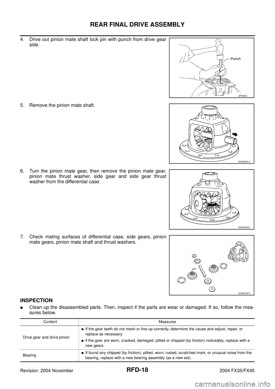
4. Drive out pinion mate shaft lock pin with punch from drive gear
side.
5. Remove the pinion mate shaft.
6. Turn the pinion mate gear, then remove the pinion mate gear,
pinion mate thrust washer, side gear and side gear thrust
washer from the differential case.
7. Check mating surfaces of differential case, side gears, pinion
mate gears, pinion mate shaft and thrust washers.
INSPECTION
�Clean up the disassembled parts. Then, inspect if the parts are wear or damaged. If so, follow the mea-
sures below.
SPD025
SDIA0031J
SDIA0032J
SDIA0187J
Content Measures
Drive gear and drive pinion
�If the gear teeth do not mesh or line-up correctly, determine the cause and adjust, repair, or
replace as necessary.
�if the gear are worn, cracked, damaged, pitted or chipped (by friction) noticeably, replace with a
new gears.
Bearing
�If found any chipped (by friction), pitted, worn, rusted, scratched mark, or unusual noise from the
bearing, replace with a new bearing assembly (as a new set).
Page 4046 of 4449
REAR FINAL DRIVE ASSEMBLY
RFD-19
C
E
F
G
H
I
J
K
L
MA
B
RFD
Revision: 2004 November 2004 FX35/FX45
ADJUSTMENT OF DIFFERENTIAL CASE
Thrust Washer Selection
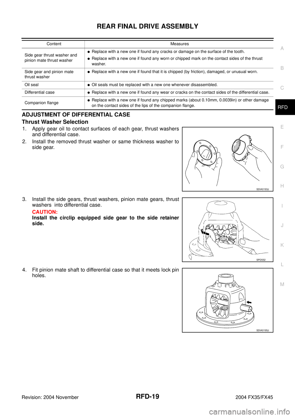
1. Apply gear oil to contact surfaces of each gear, thrust washers
and differential case.
2. Install the removed thrust washer or same thickness washer to
side gear.
3. Install the side gears, thrust washers, pinion mate gears, thrust
washers into differential case.
CAUTION:
Install the circlip equipped side gear to the side retainer
side.
4. Fit pinion mate shaft to differential case so that it meets lock pin
holes.
Side gear thrust washer and
pinion mate thrust washer�Replace with a new one if found any cracks or damage on the surface of the tooth.
�Replace with a new one if found any worn or chipped mark on the contact sides of the thrust
washer.
Side gear and pinion mate
thrust washer
�Replace with a new one if found that it is chipped (by friction), damaged, or unusual worn.
Oil seal
�Oil seals must be replaced with a new one whenever disassembled.
Differential case
�Replace with a new one if found any wear or cracks on the contact sides of the differential case.
Companion flange
�Replace with a new one if found any chipped marks (about 0.10mm, 0.0039in) or other damage
on the contact sides of the lips of the companion flange. Content Measures
SDIA0193J
SPD552
SDIA0195J
Page 4048 of 4449
REAR FINAL DRIVE ASSEMBLY
RFD-21
C
E
F
G
H
I
J
K
L
MA
B
RFD
Revision: 2004 November 2004 FX35/FX45
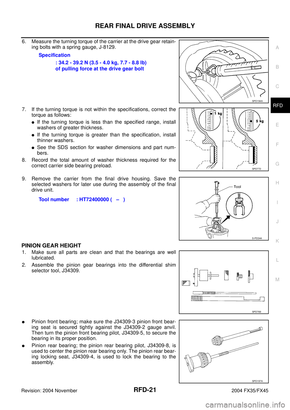
6. Measure the turning torque of the carrier at the drive gear retain-
ing bolts with a spring gauge, J-8129.
7. If the turning torque is not within the specifications, correct the
torque as follows:
�If the turning torque is less than the specified range, install
washers of greater thickness.
�If the turning torque is greater than the specification, install
thinner washers.
�See the SDS section for washer dimensions and part num-
bers.
8. Record the total amount of washer thickness required for the
correct carrier side bearing preload.
9. Remove the carrier from the final drive housing. Save the
selected washers for later use during the assembly of the final
drive unit.
PINION GEAR HEIGHT
1. Make sure all parts are clean and that the bearings are well
lubricated.
2. Assemble the pinion gear bearings into the differential shim
selector tool, J34309.
�Pinion front bearing; make sure the J34309-3 pinion front bear-
ing seat is secured tightly against the J34309-2 gauge anvil.
Then turn the pinion front bearing pilot, J34309-5, to secure the
bearing in its proper position.
�Pinion rear bearing; the pinion rear bearing pilot, J34309-8, is
used to center the pinion rear bearing only. The pinion rear bear-
ing locking seat, J34309-4, is used to lock the bearing to the
assembly.Specification
: 34.2 - 39.2 N (3.5 - 4.0 kg, 7.7 - 8.8 lb)
of pulling force at the drive gear bolt
SPD194A
SPD772
Tool number : HT72400000 ( – )
S-PD344
SPD769
SPD197A
Page 4052 of 4449
REAR FINAL DRIVE ASSEMBLY
RFD-25
C
E
F
G
H
I
J
K
L
MA
B
RFD
Revision: 2004 November 2004 FX35/FX45
1. Thoroughly clean drive gear and drive pinion teeth.
2. Lightly apply a mixture of powdered ferric oxide and oil or the
equivalent. Apply it to 3 or 4 teeth of drive gear drive side.
3. Hold companion flange steady by hand and rotate the drive gear
in both directions.
ASSEMBLY OF DIFFERENTIAL CASE ASSEMBLY
1. Install pinion mate shaft lock pin with a punch.
Make sure lock pin is flush with case.
CAUTION:
Do not reuse the lock pin. Always replace the lock pin with
a new one.
SPD357
SDIA0813E
SDIA1796E
SPD030
Page 4053 of 4449
RFD-26
REAR FINAL DRIVE ASSEMBLY
Revision: 2004 November 2004 FX35/FX45
2. Place differential case on drive gear.
3. Apply genuine medium strength locking sealant or equivalent.
Refer to GI-48, "
RECOMMENDED CHEMICAL PRODUCTS
AND SEALANTS" to drive gear bolts, and install them.
CAUTION:
Do not reuse the bolts. Always replace the bolts with a new
one.
�Tighten bolts in a crisscross fashion.
�After tightening the bolt to the specified torque, turn the bolt
31 to 36 more degrees.
4. Press-fit side bearing inner race on differential case with tool.
INSTALLATION OF DRIVE PINION ASSEMBLY
1. Press-fit front and rear bearing outer races with tools.
2. Select drive pinion height adjusting washer. Refer to RFD-31, "
AVAILABLE PINION HEIGHT ADJUSTING
WASHERS"
SPD554
Tool number A : KV38100300 (J25523)
B : ST33061000 (J8107-2)
SPD353
Tool number A : Suitable tool
B : ST30611000 (J25742-1)
C : ST30613000 (J25742-3)
SPD992
Page 4054 of 4449
REAR FINAL DRIVE ASSEMBLY
RFD-27
C
E
F
G
H
I
J
K
L
MA
B
RFD
Revision: 2004 November 2004 FX35/FX45
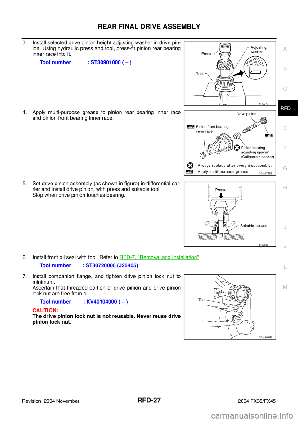
3. Install selected drive pinion height adjusting washer in drive pin-
ion. Using hydraulic press and tool, press-fit pinion rear bearing
inner race into it.
4. Apply multi-purpose grease to pinion rear bearing inner race
and pinion front bearing inner race.
5. Set drive pinion assembly (as shown in figure) in differential car-
rier and install drive pinion, with press and suitable tool.
Stop when drive pinion touches bearing.
6. Install front oil seal with tool. Refer to RFD-7, "
Removal and Installation" .
7. Install companion flange, and tighten drive pinion lock nut to
minimum.
Ascertain that threaded portion of drive pinion and drive pinion
lock nut are free from oil.
CAUTION:
The drive pinion lock nut is not reusable. Never reuse drive
pinion lock nut.Tool number : ST30901000 ( – )
SPD377
SDIA1797E
SPD896
Tool number : ST30720000 (J25405)
Tool number : KV40104000 ( – )
SDIA1011E
Page 4055 of 4449
RFD-28
REAR FINAL DRIVE ASSEMBLY
Revision: 2004 November 2004 FX35/FX45
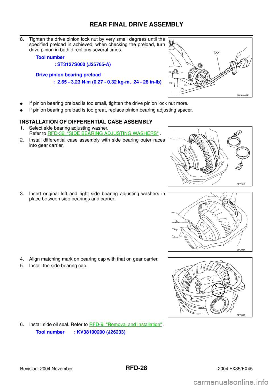
8. Tighten the drive pinion lock nut by very small degrees until the
specified preload in achieved, when checking the preload, turn
drive pinion in both directions several times.
�If pinion bearing preload is too small, tighten the drive pinion lock nut more.
�If pinion bearing preload is too great, replace pinion bearing adjusting spacer.
INSTALLATION OF DIFFERENTIAL CASE ASSEMBLY
1. Select side bearing adjusting washer.
Refer to RFD-32, "
SIDE BEARING ADJUSTING WASHERS" .
2. Install differential case assembly with side bearing outer races
into gear carrier.
3. Insert original left and right side bearing adjusting washers in
place between side bearings and carrier.
4. Align matching mark on bearing cap with that on gear carrier.
5. Install the side bearing cap.
6. Install side oil seal. Refer to RFD-9, "
Removal and Installation" . Tool number
: ST3127S000 (J25765-A)
Drive pinion bearing preload
: 2.65 - 3.23 N·m (0.27 - 0.32 kg-m, 24 - 28 in-lb)
SDIA1007E
SPD919
SPD924
SPD889
Tool number : KV38100200 (J26233)