Page 4334 of 4449

TROUBLE DIAGNOSIS FOR SYMPTOMS
TF-33
C
E
F
G
H
I
J
K
L
MA
B
TF
Revision: 2004 November 2004 FX35/FX45
2. CHECK AWD CONTROL UNIT POWER SUPPLY CIRCUIT
1. Turn ignition switch “OFF”.
2. Disconnect AWD control unit harness connector.
3. Turn ignition switch “ON”. (Do not start engine.)
4. Check voltage between AWD control unit harness connector ter-
minals and ground.
5. Turn ignition switch “OFF”.
6. Check voltage between AWD control unit harness connector ter-
minals and ground.
OK or NG
OK >> GO TO 3.
NG >> Check the following. If any items are damaged, repair or
replace damaged parts.
�10A fuse [No. 12 or 21, located in the fuse block (J/B)]
�Harness for short or open between battery and AWD control unit harness connector terminal 9
�Harness for short or open between ignition switch and AWD control unit harness connector ter-
minal 7
�Ignition switch. Refer to PG-3, "POWER SUPPLY ROUTING CIRCUIT" .
3. CHECK AWD CONTROL UNIT GROUND CIRCUIT
1. Turn ignition switch “OFF”.
2. Disconnect AWD control unit harness connector.
3. Check continuity between AWD control unit harness connector
M92 terminals 10 (B), 11 (B) and ground.
Also check harness for short to ground and short to power.
OK or NG
OK >> GO TO 4.
NG >> Repair open circuit or short to ground or short to power
in harness or connectors.
Connector Terminal (Wire color) Voltage (Approx.)
M927 (G/R) - Ground
Battery voltage
9 (G/W) - Ground
SDIA2319E
Connector Terminal (Wire color) Voltage (Approx.)
M927 (G/R) - Ground 0V
9 (G/W) - Ground Battery voltage
SDIA2320E
Continuity should exist.
SDIA1883E
Page 4341 of 4449
TF-40
REAR OIL SEAL
Revision: 2004 November 2004 FX35/FX45
REAR OIL SEALPFP:33140
Removal and InstallationADS000RQ
REMOVAL
1. Remove the rear propeller shaft. Refer to PR-6, "REAR PROPELLER SHAFT" .
2. Remove companion flange lock nut using the flange wrench.
3. Put matching mark on the end of the main shaft corresponding
to the B position matching mark on the companion flange.
CAUTION:
�For matching mark, use paint. Do not damage main shaft.
�The mark on the transfer companion flange indicates the
maximum vertical runout position.
4. Remove the companion flange using a puller.
5. Remove the rear oil seal using a tool.
CAUTION:
Be careful not to damage the rear case.Tool number : KV38108300 (J44195)
SDIA1784E
SDIA1798E
SDIA1785E
Tool number : KV381054S0 (J34286)
SDIA1786E
Page 4342 of 4449
REAR OIL SEAL
TF-41
C
E
F
G
H
I
J
K
L
MA
B
TF
Revision: 2004 November 2004 FX35/FX45
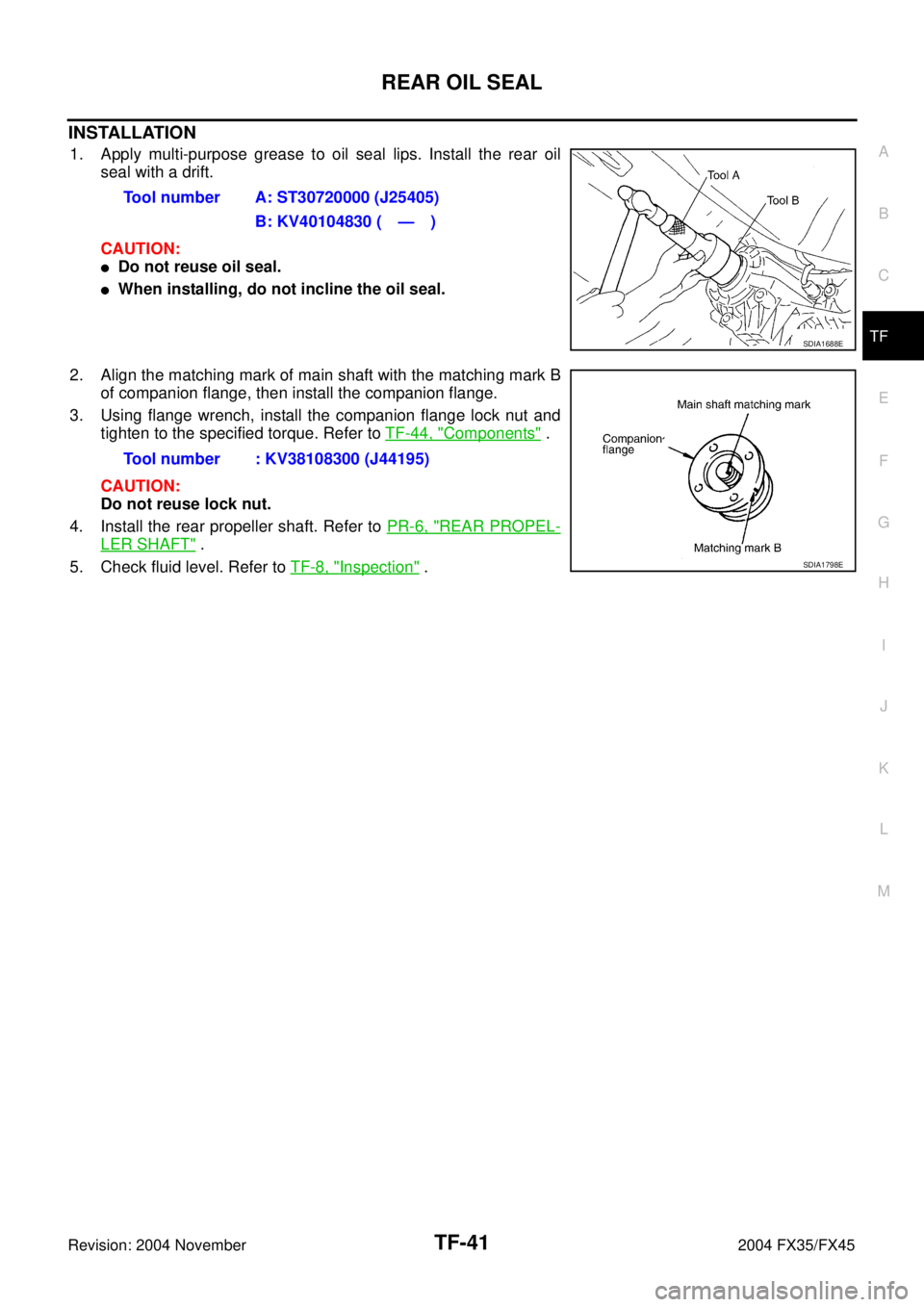
INSTALLATION
1. Apply multi-purpose grease to oil seal lips. Install the rear oil
seal with a drift.
CAUTION:
�Do not reuse oil seal.
�When installing, do not incline the oil seal.
2. Align the matching mark of main shaft with the matching mark B
of companion flange, then install the companion flange.
3. Using flange wrench, install the companion flange lock nut and
tighten to the specified torque. Refer to TF-44, "
Components" .
CAUTION:
Do not reuse lock nut.
4. Install the rear propeller shaft. Refer to PR-6, "
REAR PROPEL-
LER SHAFT" .
5. Check fluid level. Refer to TF-8, "
Inspection" . Tool number A: ST30720000 (J25405)
B: KV40104830 ( — )
SDIA1688E
Tool number : KV38108300 (J44195)
SDIA1798E
Page 4345 of 4449
TF-44
TRANSFER ASSEMBLY
Revision: 2004 November 2004 FX35/FX45
ComponentsADS000RT
1. Front case 2. Front oil seal 3. Main shaft oil seal
4. Main shaft bearing 5. Snap ring (hole) 6. Main shaft
7. Needle bearing 8. Sprocket 9. Bolts
10. Electric controlled coupling 11. Oil cover 12. Spacer
13. Snap ring (shaft) 14. Rear bearing 15. Snap ring (hole)
16. Rear oil seal 17. Spacer 18. Companion flange lock nut
19. Companion flange 20. Baffle plate 21. Rear case
22. Filler plug 23. Oil gutter 24. Seal washer
25. Drain plug 26. Retainer 27. Drive chain
28. Front drive shaft rear bearing 29. Front drive shaft 30. Front drive shaft front bearing
31. Dynamic damper 32. Dynamic damper bracket
SDIA2311E
Page 4347 of 4449
TF-46
TRANSFER ASSEMBLY
Revision: 2004 November 2004 FX35/FX45
4. Remove snap ring from front case.
5. Remove main shaft bearing from front case.
Rear Case
1. Remove the drive chain and front drive shaft from rear case.
2. Remove companion flange lock nut from main shaft using the
flange wrench.
3. Put matching mark on the end of the main shaft corresponding
to the B position matching mark on the companion flange.
SDIA1601E
SDIA1595E
SDIA1693E
Tool number : KV38108300 (J44195)
SDIA1694E
SDIA1798E
Page 4350 of 4449

TRANSFER ASSEMBLY
TF-49
C
E
F
G
H
I
J
K
L
MA
B
TF
Revision: 2004 November 2004 FX35/FX45
Main Shaft and Electric Controlled Coupling
1. Remove the snap ring from main shaft.
2. Remove the spacer, electric controlled coupling, sprocket and
needle bearing from main shaft.
INSPECTION
Gears
�Check the gear faces and shaft for wear, cracks, damage, and seizure.
Bearings
�Check for seizure, peeling, wear, corrosion, sticking/abnormal noise/roughness in hand turning, and other
damage.
CAUTION:
When replacing the bearing, always replace the inner race and outer race as a pair.
Front Case and Rear Case
�Replace with a new one if found any wear or cracks on the contact sides of the case.
Washers
�Check for seizure, damage, and unusual wear.
Oil Seals
�Discard old oil seals, replace with new ones.
�If wear, deterioration of adherence (sealing force of lips), or damage is detected on the lips, replace them.
Snap Ring
�Discard old snap rings, replace with new ones.
Lock Nut
�Discard old lock nut, replace with new ones.
ASSEMBLY
Rear Case
1. Install the baffle plate into rear case.
2. Install the main shaft rear bearing into rear case.
SDIA1602E
SDIA1701E
Page 4354 of 4449
TRANSFER ASSEMBLY
TF-53
C
E
F
G
H
I
J
K
L
MA
B
TF
Revision: 2004 November 2004 FX35/FX45
2. Install the coupling connector to rear case.
3. Install coupling connector to the ring after applying grease to the
ring.
4. Install the retainer to connector.
5. Install the oil cover and temperature sensor bolt into rear case.
Using harness dolly of oil cover, install electric controlled cou-
pling harness between dolly and case.
6. Install the oil gutter into rear case.
7. Install the companion flange and spacer to main shaft.
8. Install companion flange lock nut to companion flange.
CAUTION:
Do not companion flange lock nut.
SDIA1597E
SDIA1728E
SDIA1598E
SDIA1694E
Page 4395 of 4449

WW-4
FRONT WIPER AND WASHER SYSTEM
Revision: 2004 November 2004 FX35/FX45
FRONT WIPER AND WASHER SYSTEMPFP:28810
Components Parts and Harness Connector LocationAKS0056O
System DescriptionAKS0056P
�All front wiper relays (HI, LO) are included in IPDM E/R.
�Wiper switch (combination switch) is composed of a combination of 5 output terminals and 5 input termi-
nals. Terminal combination status is read by BCM when switch is turned ON.
�BCM controls front wiper LO, HI, and INT (intermittent) operation.
�IPDM E/R operates wiper motor according to CAN communication signals from BCM.
Power is supplied at all times
�through 50 A fusible link (letter M, located in fusible link block)
�to BCM (body control module) terminal 55
�through 15 A fuse [No. 22, located in fuse block (J/B)]
�to BCM (body control module) terminal 42
�through 30 A fuse [No. 73, located in IPDM E/R (intelligent power distribution module engine room)]
�to front wiper relay [located in IPDM E/R (intelligent power distribution module engine room)]
�through 15 A fuse [No. 78, located in IPDM E/R (intelligent power distribution module engine room)]
�to CPU (central processing unit) [located in IPDM E/R (intelligent power distribution module engine room)]
�through 10 A fuse [No. 71, located in IPDM E/R (intelligent power distribution module engine room)]
�to CPU (central processing unit) [located in IPDM E/R (intelligent power distribution module engine
room)].
When the ignition switch ON or START position, power is supplied
�through 15 A fuse [No. 1, located in fuse block (J/B)]
�to BCM (body control module) terminal 38
�through ignition relay [located in IPDM E/R (intelligent power distribution module engine room)]
�to front wiper relay [located in IPDM E/R (intelligent power distribution module engine room)]
SKIA5289E

 6. Main shaft
7. Need")

