Page 323 of 4449

AT-246
ON-VEHICLE SERVICE
Revision: 2004 November 2004 FX35/FX45
Installation
CAUTION:
After completing installation, check A/T fluid leakage and fluid level. Refer to AT- 1 2 , "
Changing A/T
Fluid" , AT- 1 2 , "Checking A/T Fluid" .
1. Install O-ring in A/T assembly harness connector.
CAUTION:
�Do not reuse O-ring.
�Apply ATF to O-ring.
2. Install A/T fluid temperature sensor 2 to bracket.
3. Install A/T fluid temperature sensor 2 in control valve with TCM.
(With bracket.)
CAUTION:
Adjust bolt hole of bracket to bolt hole of control valve with
TCM.
4. Install control valve with TCM in transmission case.
CAUTION:
�Make sure that turbine revolution sensor securely installs
turbine revolution sensor hole.
�Hang down revolution sensor harness toward outside so
as not to disturb installation of control valve with TCM.
�Adjust A/T assembly harness connector of control valve
with TCM to terminal hole of transmission case.
SCIA5155E
SCIA5264E
: 7.9 N·m (0.81 kg-m, 70 in-lb)
SCIA5301E
SCIA5034E
Page 324 of 4449
ON-VEHICLE SERVICE
AT-247
D
E
F
G
H
I
J
K
L
MA
B
AT
Revision: 2004 November 2004 FX35/FX45
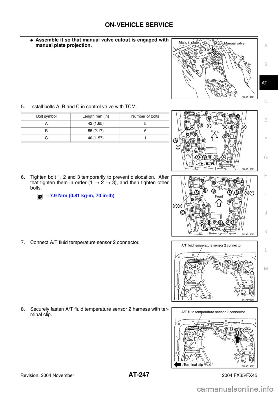
�Assemble it so that manual valve cutout is engaged with
manual plate projection.
5. Install bolts A, B and C in control valve with TCM.
6. Tighten bolt 1, 2 and 3 temporarily to prevent dislocation. After
that tighten them in order (1 → 2 → 3), and then tighten other
bolts.
7. Connect A/T fluid temperature sensor 2 connector.
8. Securely fasten A/T fluid temperature sensor 2 harness with ter-
minal clip.
SCIA5142E
Bolt symbol Length mm (in) Number of bolts
A 42 (1.65) 5
B 55 (2.17) 6
C 40 (1.57) 1
SCIA5139E
: 7.9 N·m (0.81 kg-m, 70 in-lb)
SCIA5140E
SCIA5023E
SCIA5146E
Page 326 of 4449

ON-VEHICLE SERVICE
AT-249
D
E
F
G
H
I
J
K
L
MA
B
AT
Revision: 2004 November 2004 FX35/FX45
c. Tighten oil pan mounting bolts to the specified torque in numeri-
cal order as shown in the figure after temporarily tightening
them.
CAUTION:
Do not reuse oil pan mounting bolts.
13. Install drain plug to oil pan.
CAUTION:
Do not reuse drain plug gasket.
14. Pull up A/T assembly harness connector.
CAUTION:
Be careful not to damage connector.
15. Install snap ring to A/T assembly harness connector.
16. Connect A/T assembly harness connector.
17. Connect heated oxygen sensor 2 harness connector.
18. Install front cross bar. Refer to FSU-8, "
Components" .
19. Pour ATF into transmission assembly. Refer to AT- 1 2 , "
Chang-
ing A/T Fluid" .
20. Connect the battery cable to the negative terminal.
A/T FLUID TEMPERATURE SENSOR 2 REMOVAL AND INSTALLATION
Removal
1. Disconnect the battery cable from the negative terminal.
2. Remove front cross bar. Refer to FSU-8, "
Components" .
3. Disconnect heated oxygen sensor 2 harness connector.
4. Drain ATF through drain plug.
5. Remove oil pan and oil pan gasket.: 7.9 N·m (0.81 kg-m, 70 in-lb)
: 34 N·m (3.5 kg-m, 25 ft-lb)
SCIA2492E
SCIA5038E
SCIA5039E
SCIA2308E
Page 327 of 4449
AT-250
ON-VEHICLE SERVICE
Revision: 2004 November 2004 FX35/FX45
6. Check foreign materials in oil pan to help determine causes of
malfunction. If the fluid is very dark, smells burned, or contains
foreign particles, the frictional material (clutches, band) may
need replacement. A tacky film that will not wipe clean indicates
varnish build up. Varnish can cause valves, servo, and clutches
to stick and can inhibit pump pressure.
�If frictional material is detected, perform A/T fluid cooler
cleaning. Refer to AT- 1 4 , "
A/T Fluid Cooler Cleaning" .
7. Disconnect A/T fluid temperature sensor 2 connector.
CAUTION:
Be careful not to damage connector.
8. Straighten terminal clip to free A/T fluid temperature sensor 2
harness.
9. Remove A/T fluid temperature sensor 2 with bracket from con-
trol valve with TCM.
10. Remove bracket from A/T fluid temperature sensor 2.
SCIA5199E
SCIA5023E
SCIA5146E
SCIA5302E
SCIA5264E
Page 328 of 4449
ON-VEHICLE SERVICE
AT-251
D
E
F
G
H
I
J
K
L
MA
B
AT
Revision: 2004 November 2004 FX35/FX45
Installation
CAUTION:
After completing installation, check A/T fluid leakage and fluid level. Refer to AT- 1 2 , "
Changing A/T
Fluid" , AT- 1 2 , "Checking A/T Fluid" .
1. Install A/T fluid temperature sensor 2 to bracket.
2. Install A/T fluid temperature sensor 2 in control valve with TCM.
(With bracket.)
3. Connect A/T fluid temperature sensor 2 connector.
4. Securely fasten A/T fluid temperature sensor 2 harness with ter-
minal clip.
5. Install oil pan to transmission case.
a. Install oil pan gasket to oil pan.
CAUTION:
�Do not reuse oil pan gasket.
�Install it in the direction to align hole positions.
�Complete remove all moisture, oil and old gasket, etc. from oil pan mounting surface.
SCIA5264E
: 7.9 N·m (0.81 kg-m, 70 in-lb)
SCIA5302E
SCIA5023E
SCIA5146E
Page 356 of 4449
OVERHAUL
AT-279
D
E
F
G
H
I
J
K
L
MA
B
AT
Revision: 2004 November 2004 FX35/FX45
7. Pawl shaft 8. Seal ring 9. Needle bearing
10. Revolution sensor 11. Parking gear 12. Output shaft
13. Bearing race 14. Needle bearing 15. Manual plate
16. Parking rod 17. Manual shaft oil seal 18. Manual shaft
19. O-ring 20. Band servo anchor end pin 21. Detent spring
22. Spacer 23. Seal ring 24. Snap ring
25. O-ring 26. Transmission case 27. Retaining pin
28. Return spring 29. O-ring 30. Servo assembly
31. Snap ring 32. Control valve with TCM 33. Bracket
34. A/T fluid temperature sensor 2 35. Oil pan gasket 36. Oil pan
37. Magnet 38. Drain plug 39. Drain plug gasket
40. Oil pan mounting bolt
Page 358 of 4449
OVERHAUL
AT-281
D
E
F
G
H
I
J
K
L
MA
B
AT
Revision: 2004 November 2004 FX35/FX45
7. Pawl shaft 8. Self-sealing bolt 9. Seal ring
10. Needle bearing 11. Gasket 12. Revolution sensor
13. Parking gear 14. Output shaft 15. Bearing race
16. Needle bearing 17. Manual plate 18. Parking rod
19. Manual shaft oil seal 20. Manual shaft 21. O-ring
22. Band servo anchor end pin 23. Detent spring 24. Spacer
25. Seal ring 26. Return spring 27. O-ring
28. Servo assembly 29. Snap ring 30. Control valve with TCM
31. Bracket 32. A/T fluid temperature sensor 2 33. Oil pan
34. Magnet 35. Drain plug 36. Drain plug gasket
37. Oil pan mounting bolt 38. Oil pan gasket 39. O-ring
40. Snap ring 41. Transmission case 42. Retaining pin
Page 369 of 4449
AT-292
DISASSEMBLY
Revision: 2004 November 2004 FX35/FX45
28. Remove oil pan and oil pan gasket.
29. Check foreign materials in oil pan to help determine causes of
malfunction. If the A/T fluid is very dark, smells burned, or con-
tains foreign particles, the frictional material (clutches, band)
may need replacement. A tacky film that will not wipe clean indi-
cates varnish build up. Varnish can cause valves, servo, and
clutches to stick and can inhibit pump pressure.
�If frictional material is detected, perform A/T fluid cooler
cleaning. Refer to AT- 1 4 , "
A/T Fluid Cooler Cleaning" .
30. Remove magnets from oil pan.
31. Disconnect A/T fluid temperature sensor 2 connector.
CAUTION:
Be careful not to damage connector.
32. Straighten terminal clip to free A/T fluid temperature sensor 2
harness.
SCIA2308E
SCIA5199E
SCIA5200E
SCIA5023E
SCIA5146E