AWD SYSTEM
TF-9
C
E
F
G
H
I
J
K
L
MA
B
TF
Revision: 2004 November 2004 FX35/FX45
AWD SYSTEMPFP:41650
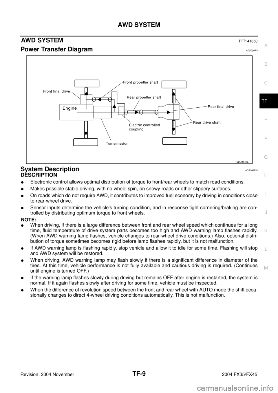
Power Transfer DiagramADS000RV
System DescriptionADS000RW
DESCRIPTION
�Electronic control allows optimal distribution of torque to front/rear wheels to match road conditions.
�Makes possible stable driving, with no wheel spin, on snowy roads or other slippery surfaces.
�On roads which do not require AWD, it contributes to improved fuel economy by driving in conditions close
to rear-wheel drive.
�Sensor inputs determine the vehicle's turning condition, and in response tight cornering/braking are con-
trolled by distributing optimum torque to front wheels.
NOTE:
�When driving, if there is a large difference between front and rear wheel speed which continues for a long
time, fluid temperature of drive system parts becomes too high and AWD warning lamp flashes rapidly.
(When AWD warning lamp flashes, vehicle changes to rear-wheel drive conditions.) Also, optional distri-
bution of torque sometimes becomes rigid before lamp flashes rapidly, but it is not malfunction.
�If AWD warning lamp is flashing rapidly, stop vehicle and allow it to idle for some time. Flashing will stop
and AWD system will be restored.
�When driving, AWD warning lamp may flash slowly if there is a significant difference in diameter of the
tires. At this time, vehicle performance is not fully available and cautious driving is required. (Continues
until engine is turned OFF.)
�If the warning lamp flashes slowly during driving but remains OFF after engine is restarted, the system is
normal. If it again flashes slowly after driving for some time, vehicle must be inspected.
�When the difference of revolution speed between the front and rear wheel with AUTO mode the shift occa-
sionally changes to direct 4-wheel driving conditions automatically. This is not malfunction.
SDIA1611E
TRANSFER ASSEMBLY
TF-53
C
E
F
G
H
I
J
K
L
MA
B
TF
Revision: 2004 November 2004 FX35/FX45
2. Install the coupling connector to rear case.
3. Install coupling connector to the ring after applying grease to the
ring.
4. Install the retainer to connector.
5. Install the oil cover and temperature sensor bolt into rear case.
Using harness dolly of oil cover, install electric controlled cou-
pling harness between dolly and case.
6. Install the oil gutter into rear case.
7. Install the companion flange and spacer to main shaft.
8. Install companion flange lock nut to companion flange.
CAUTION:
Do not companion flange lock nut.
SDIA1597E
SDIA1728E
SDIA1598E
SDIA1694E