Page 1 of 4449

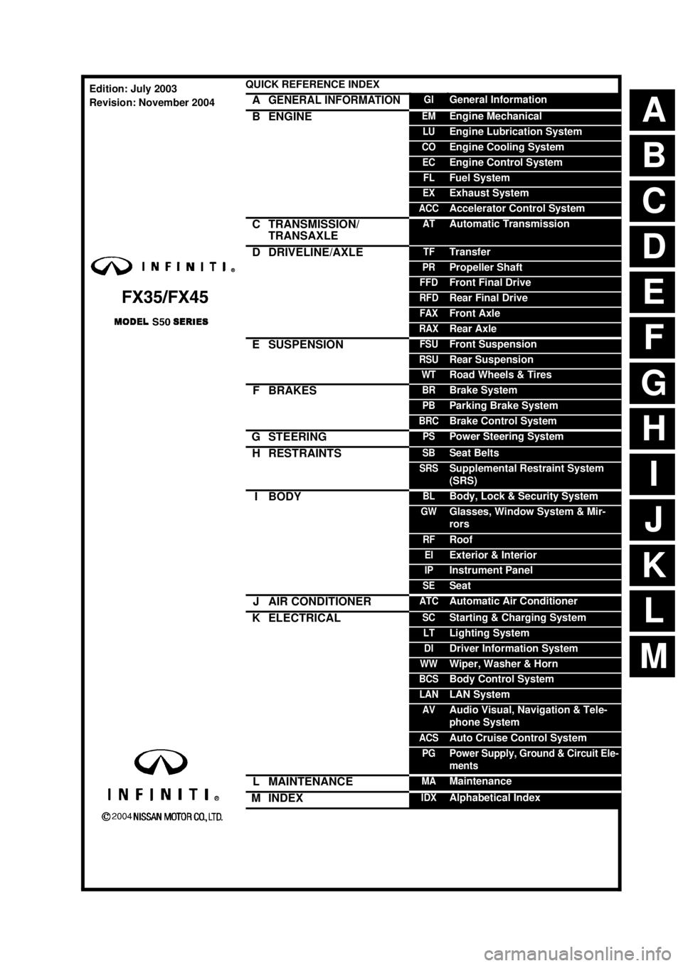
ABCDEFGHIJKMLQUICK REFERENCE INDEX AGENERAL INFORMATIONGIGeneral InformationBENGINEEMEngine MechanicalLUEngine Lubrication SystemCOEngine Cooling SystemECEngine Control SystemFLFuel SystemEXExhaust SystemACCAccelerator Control SystemCTRANSMISSION/
TRANSAXLEATAutomatic TransmissionDDRIVELINE/AXLETFTransferPRPropeller ShaftFFDFront Final DriveRFDRear Final DriveFAXFront AxleRAXRear AxleESUSPENSIONFSUFront SuspensionRSURear SuspensionWTRoad Wheels & TiresFBRAKESBRBrake SystemPBParking Brake SystemBRCBrake Control SystemGSTEERINGPSPower Steering SystemHRESTRAINTSSBSeat BeltsSRSSupplemental Restraint System
(SRS)IBODYBLBody, Lock & Security SystemGWGlasses, Window System & Mir-
rorsRFRoofEIExterior & InteriorIPInstrument PanelSESeatJAIR CONDITIONERATCAutomatic Air ConditionerKELECTRICALSCStarting & Charging SystemLTLighting SystemDIDriver Information SystemWWWiper, Washer & HornBCSBody Control SystemLANLAN SystemAVAudio Visual, Navigation & Tele-
phone SystemACSAuto Cruise Control SystemPGPower Supply, Ground & Circuit Ele-
mentsLMAINTENANCEMAMaintenanceMINDEXIDXAlphabetical IndexEdition: July 2003
Revision: November 2004
Page 129 of 4449

AT-52
TROUBLE DIAGNOSIS
Revision: 2004 November 2004 FX35/FX45
CAUTION:
Run the engine at idle for at least one minute.
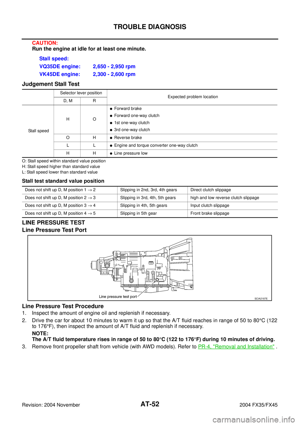
Judgement Stall Test
O: Stall speed within standard value position
H: Stall speed higher than standard value
L: Stall speed lower than standard value
Stall test standard value position
LINE PRESSURE TEST
Line Pressure Test Port
Line Pressure Test Procedure
1. Inspect the amount of engine oil and replenish if necessary.
2. Drive the car for about 10 minutes to warm it up so that the A/T fluid reaches in range of 50 to 80°C (122
to 176°F), then inspect the amount of A/T fluid and replenish if necessary.
NOTE:
The A/T fluid temperature rises in range of 50 to 80°C (122 to 176°F) during 10 minutes of driving.
3. Remove front propeller shaft from vehicle (with AWD models). Refer to PR-4, "
Removal and Installation" . Stall speed:
VQ35DE engine: 2,650 - 2,950 rpm
VK45DE engine: 2,300 - 2,600 rpm
Selector lever position
Expected problem location
D, M R
Stall speedHO
�Forward brake
�Forward one-way clutch
�1st one-way clutch
�3rd one-way clutch
OH
�Reverse brake
LL
�Engine and torque converter one-way clutch
HH
�Line pressure low
Does not shift up D, M position 1 → 2 Slipping in 2nd, 3rd, 4th gears Direct clutch slippage
Does not shift up D, M position 2 → 3 Slipping in 3rd, 4th, 5th gears high and low reverse clutch slippage
Does not shift up D, M position 3 → 4 Slipping in 4th, 5th gears Input clutch slippage
Does not shift up D, M position 4 → 5 Slipping in 5th gear Front brake slippage
SCIA2187E
Page 330 of 4449
ON-VEHICLE SERVICE
AT-253
D
E
F
G
H
I
J
K
L
MA
B
AT
Revision: 2004 November 2004 FX35/FX45
Parking Components (2WD Models Only)ACS007H0
COMPONENTS
REMOVAL
1. Drain ATF through drain plug.
2. Remove exhaust front tube and center muffler with power tool. Refer to EX-3, "
Removal and Installation" .
3. Remove rear propeller shaft. Refer to PR-7, "
Removal and Installation" .
4. Support transmission assembly with a transmission jack.
CAUTION:
When setting transmission jack, be careful not to allow it to collide against the drain plug.
5. Remove engine rear member with power tool. Refer to AT- 2 6 6 , "
Removal and Installation (2WD Models)"
.
1. Rear oil seal 2. Rear extension 3. Parking actuator support
4. Parking pawl 5. Return spring 6. Pawl shaft
7. Self-sealing bolt 8. Seal ring 9. Parking gear
10. Output shaft 11. Bearing race 12. Needle bearing
SCIA5216E
Page 335 of 4449

AT-258
ON-VEHICLE SERVICE
Revision: 2004 November 2004 FX35/FX45
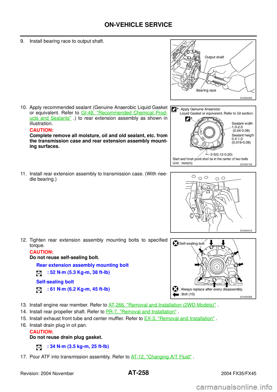
9. Install bearing race to output shaft.
10. Apply recommended sealant (Genuine Anaerobic Liquid Gasket
or equivalent. Refer to GI-48, "
Recommended Chemical Prod-
ucts and Sealants" .) to rear extension assembly as shown in
illustration.
CAUTION:
Complete remove all moisture, oil and old sealant, etc. from
the transmission case and rear extension assembly mount-
ing surfaces.
11. Install rear extension assembly to transmission case. (With nee-
dle bearing.)
12. Tighten rear extension assembly mounting bolts to specified
torque.
CAUTION:
Do not reuse self-sealing bolt.
13. Install engine rear member. Refer to AT- 2 6 6 , "
Removal and Installation (2WD Models)" .
14. Install rear propeller shaft. Refer to PR-7, "
Removal and Installation" .
15. Install exhaust front tube and center muffler. Refer to EX-3, "
Removal and Installation" .
16. Install drain plug in oil pan.
CAUTION:
Do not reuse drain plug gasket.
17. Pour ATF into transmission assembly. Refer to AT- 1 2 , "
Changing A/T Fluid" .
SCIA5245E
SCIA5212E
SCIA3431E
Rear extension assembly mounting bolt
: 52 N·m (5.3 Kg-m, 38 ft-lb)
Self-sealing bolt
: 61 N·m (6.2 Kg-m, 45 ft-lb)
SCIA3426E
: 34 N·m (3.5 kg-m, 25 ft-lb)
Page 336 of 4449

ON-VEHICLE SERVICE
AT-259
D
E
F
G
H
I
J
K
L
MA
B
AT
Revision: 2004 November 2004 FX35/FX45
Rear Oil SealACS007H1
REMOVAL
1. Remove center muffler with power tool. Refer to EX-3, "Removal
and Installation" .
2. Remove rear propeller shaft. Refer to PR-7, "
Removal and
Installation" .
3. Remove transfer assembly from transmission assembly (AWD
models). Refer to TF-43, "
Removal and Installation" .
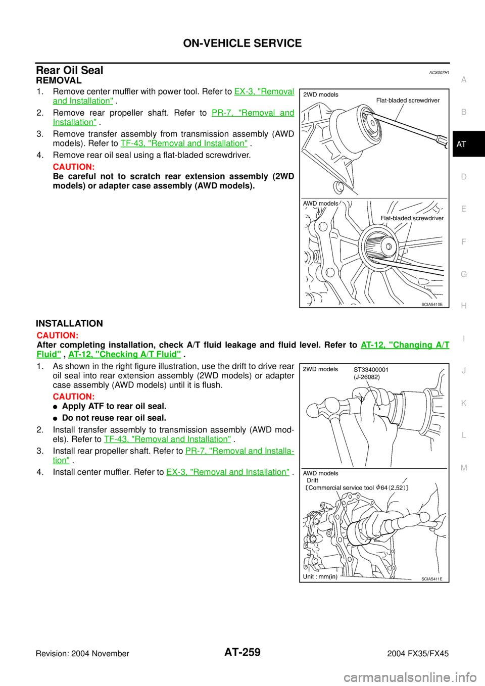
4. Remove rear oil seal using a flat-bladed screwdriver.
CAUTION:
Be careful not to scratch rear extension assembly (2WD
models) or adapter case assembly (AWD models).
INSTALLATION
CAUTION:
After completing installation, check A/T fluid leakage and fluid level. Refer to AT- 1 2 , "
Changing A/T
Fluid" , AT- 1 2 , "Checking A/T Fluid" .
1. As shown in the right figure illustration, use the drift to drive rear
oil seal into rear extension assembly (2WD models) or adapter
case assembly (AWD models) until it is flush.
CAUTION:
�Apply ATF to rear oil seal.
�Do not reuse rear oil seal.
2. Install transfer assembly to transmission assembly (AWD mod-
els). Refer to TF-43, "
Removal and Installation" .
3. Install rear propeller shaft. Refer to PR-7, "
Removal and Installa-
tion" .
4. Install center muffler. Refer to EX-3, "
Removal and Installation" .
SCIA5410E
SCIA5411E
Page 337 of 4449

AT-260
ON-VEHICLE SERVICE
Revision: 2004 November 2004 FX35/FX45
Revolution Sensor Components (2WD Models Only)ACS007H2
COMPONENTS
REMOVAL
1. Disconnect the battery cable from the negative terminal.
2. Drain ATF through drain plug.
3. Remove front cross bar. Refer to FSU-8, "
Components" .
4. Remove exhaust front tube and center muffler with power tool. Refer to EX-3, "
Removal and Installation" .
5. Remove rear propeller shaft. Refer to PR-7, "
Removal and Installation" .
6. Remove oil pan and oil pan gasket.
7. Support transmission assembly with a transmission jack.
CAUTION:
When setting transmission jack, place wooden blocks to
prevent from damaging control valve with TCM and trans-
mission case.
8. Remove engine rear member with power tool. Refer to AT- 2 6 6 ,
"Removal and Installation (2WD Models)" .
1. Rear extension 2. Transmission 3. Revolution sensor
4. Oil pan gasket 5. Oil pan 6. Oil pan mounting bolt
7. Drain plug gasket 8. Drain plug 9. Self-sealing bolt
SCIA5145E
SCIA2308E
Page 340 of 4449

ON-VEHICLE SERVICE
AT-263
D
E
F
G
H
I
J
K
L
MA
B
AT
Revision: 2004 November 2004 FX35/FX45
6. Tighten rear extension assembly mounting bolts to specified
torque.
CAUTION:
Do not reuse self-sealing bolt.
7. Install engine rear member. Refer to AT- 2 6 6 , "
Removal and Installation (2WD Models)" .
8. Install oil pan to transmission case.
a. Install oil pan gasket to oil pan.
CAUTION:
�Do not reuse oil pan gasket.
�Install it in the direction to align hole positions.
�Complete remove all moisture, oil and old gasket, etc. from oil pan mounting surface.
b. Install oil pan (with oil pan gasket) to transmission case.
CAUTION:
�Install it so that drain plug comes to the position as
shown in the figure.
�Be careful not to pinch harnesses.
�Complete remove all moisture, oil and old gasket, etc.
from oil pan mounting surface.
c. Tighten oil pan mounting bolts to the specified torque in numeri-
cal order as shown in the figure after temporarily tightening
them.
CAUTION:
Do not reuse oil pan mounting bolts.
9. Install drain plug to oil pan.
CAUTION:
Do not reuse drain plug gasket.
10. Install rear propeller shaft. Refer to PR-7, "
Removal and Installation" .
11. Install exhaust front tube and center muffler. Refer to EX-3, "
Removal and Installation" .
12. Install front cross bar. Refer to FSU-8, "
Components" .
13. Pour ATF into transmission assembly. Refer to AT- 1 2 , "
Changing A/T Fluid" .
14. Connect the battery cable to the negative terminal.Rear extension assembly mounting bolt
: 52 N·m (5.3 Kg-m, 38 ft-lb)
Self-sealing bolt
: 61 N·m (6.2 Kg-m, 45 ft-lb)
SCIA3426E
SCIA2308E
: 7.9 N·m (0.81 kg-m, 70 in-lb)
: 34 N·m (3.5 kg-m, 25 ft-lb)
SCIA2492E
Page 343 of 4449

AT-266
TRANSMISSION ASSEMBLY
Revision: 2004 November 2004 FX35/FX45
TRANSMISSION ASSEMBLYPFP:31020
Removal and Installation (2WD Models)ACS002S1
COMPONENTS
REMOVAL
CAUTION:
When removing the A/T assembly from engine, first remove the crankshaft position sensor (POS) from
the A/T assembly.
Be careful not to damage sensor edge.
1. Disconnect the battery cable from the negative terminal.
2. Remove engine cover.
3. Remove A/T fluid level gauge.
4. Remove engine under cover with power tool.
5. Remove front cross bar. Refer to FSU-8, "
Components" .
6. Remove exhaust front tube and center muffler with power tool. Refer to EX-3, "
Removal and Installation" .
7. Remove three way catalyst. Refer to EM-26, "
Removal and Installation" .
8. Remove rear propeller shaft. Refer to PR-7, "
Removal and Installation" .
9. Remove control rod. Refer to AT- 2 3 3 , "
Control Device Removal and Installation" .
1. Transmission assembly 2. A/T fluid charging pipe 3. O-ring
4. Fluid cooler tube 5. Copper washer 6. A/T fluid level gauge
7. Engine rear member 8. Insulator
SCIA5050E