Page 441 of 4449

ATC-12
PRECAUTIONS
Revision: 2004 November 2004 FX35/FX45
CAUTION:
The new and former refrigerant connections use different O-ring configurations. Do not confuse O-
rings since they are not interchangeable. If a wrong O-ring is installed, refrigerant will leak at, or
around, the connection.
O-Ring Part Numbers and Specifications
WARNING:
Make sure all refrigerant is discharged into the recycling equipment and the pressure in the system is
less than atmospheric pressure. Then gradually loosen the discharge side hose fitting and remove it.
CAUTION:
When replacing or cleaning refrigerant cycle components, observe the following.
�When the compressor is removed, store it in the same position as it is when mounted on the car.
Malfunction to do so will cause lubricant to enter the low-pressure chamber.
�When connecting tubes, always use a torque wrench and a back-up wrench.
�After disconnecting tubes, immediately plug all openings to prevent entry of dirt and moisture.
�When installing an air conditioner in the vehicle, connect the pipes as the final stage of the opera-
tion. Do not remove the seal caps of pipes and other components until just before required for
connection.
�Allow components stored in cool areas to warm to working area temperature before removing seal
caps. This prevents condensation from forming inside A/C components.
�Thoroughly remove moisture from the refrigeration system before charging the refrigerant.
�Always replace used O-rings.
�When connecting tube, apply lubricant to circle of the O-rings shown in illustration. Be careful not
to apply lubricant to threaded portion.
Lubricant name: Nissan A/C System Oil Type S
Part number: KLH00-PAGS0
�O-ring must be closely attached to dented portion of tube.
�When replacing the O-ring, be careful not to damage O-ring and tube.
�Connect tube until you hear it click, then tighten the nut or bolt by hand until snug. Make sure that
the O-ring is installed to tube correctly.
Connection type Piping connection point Part number QTY O-ring size
NewLow-pressure pipe 1 to low-pressure pipe 2 (One-touch joint) 92473 N8221 2 16
Low-pressure pipe 2 to expansion valve 92473 N8210 1 16
High-pressure pipe 1 to high-pressure pipe 2 (One-touch joint) 92471 N8221 2 8
High-pressure pipe 3 to expansion valve 92471 N8210 1 8
High-pressure pipe 2 to high-pressure pipe 3 (One-touch joint) 92471 N8221 2 8
Condenser to high-pressure flexible hose (One-touch joint) 92472 N8221 2 12
Condenser to high-pressure pipe 1 (One-touch joint) 92471 N8221 2 8
Low-pressure flexible hose to low-pressure pipe 1 (One-touch
joint)92473 N8221 2 16
Compressor to low-pressure flexible hose 92474 N8210 1 19
Compressor to high-pressure flexible hose 92472 N8210 1 12
Liquid tank to condenser pipeInlet
92471 N82101
8
Outlet 1
FormerRefrigerant pressure sensor to condenser J2476 89956 1 10
Expansion valve to evaporatorInlet 92475 71L00 1 12
Outlet 92475 72L00 1 16
Page 450 of 4449

REFRIGERATION SYSTEM
ATC-21
C
D
E
F
G
H
I
K
L
MA
B
AT C
Revision: 2004 November 2004 FX35/FX45
REFRIGERATION SYSTEMPFP:KA990
Refrigerant CycleAJS00146
REFRIGERANT FLOW
The refrigerant flows in the standard pattern, that is, through the compressor, the condenser with liquid tank,
through the evaporator, and back to the compressor. The refrigerant evaporation through the evaporator coil is
controlled by an externally equalized expansion valve, located inside the evaporator case.
FREEZE PROTECTION
Under usual operating conditions, when the A/C is switched on, the compressor runs continuously, and the
evaporator pressure, and therefore, temperature is controlled by the compressor to prevent freeze up.
Refrigerant System ProtectionAJS00147
REFRIGERANT PRESSURE SENSOR
The refrigerant system is protected against excessively high- or low-pressure by the refrigerant pressure sen-
sor, located on the condenser. If the system pressure rises above, or falls below the specifications, the refrig-
erant pressure sensor detects the pressure inside the refrigerant line and sends the voltage signal to the ECM.
ECM makes the A/C relay go OFF and stops the compressor when pressure on the high-pressure side
detected by refrigerant pressure sensor is over about 2,746 kPa (28 kg/cm
2 , 398 psi), or below about 134 kPa
(1.4 kg/cm
2 , 20 psi).
PRESSURE RELIEF VALVE
The refrigerant system is also protected by a pressure relief valve, located in the rear head of the compressor.
When the pressure of refrigerant in the system increases to an unusual level [more than 3,727 kPa (38 kg/cm
2
, 540 psi)], the release port on the pressure relief valve automatically opens and releases refrigerant into the
atmosphere.
RJIA0849E
Page 482 of 4449
TROUBLE DIAGNOSIS
ATC-53
C
D
E
F
G
H
I
K
L
MA
B
AT C
Revision: 2004 November 2004 FX35/FX45
Self-diagnosis FunctionAJS0014P
DESCRIPTION
The self-diagnostic system diagnoses sensors, door motors, blower motor, etc. by system line. Refer to appli-
cable sections (items) for details. Shifting from usual control to the self-diagnostic system is accomplished by
starting the engine (turning the ignition switch ON) and pressing OFF switch for at least 5 seconds. The OFF
switch must be pressed within 10 seconds after starting the engine (ignition switch is turned ON). This system
will be canceled by either pressing AUTO switch or turning the ignition switch OFF. Shifting from one step to
another is accomplished by means of pressing temperature switch (driver side), as required.
Additionally shifting from STEP-5 to AUXILIARY MECHANISM is accomplished by means of pressing (fan)
UP switch.
RJIA1967E
Page 483 of 4449

ATC-54
TROUBLE DIAGNOSIS
Revision: 2004 November 2004 FX35/FX45
FUNCTION CONFIRMATION PROCEDURE
1. SET IN SELF-DIAGNOSTIC MODE
1. Turn ignition switch ON.
2. Set in self-diagnostic mode as follows. Within 10 seconds after starting engine (ignition switch is turned
ON.), press OFF switch for at least 5 seconds.
CAUTION:
�If battery voltage drops below 12V during diagnosis STEP-3, actuator speed becomes slower and
as a result, the system may generate an error even when operation is usual. To avoid this, start
engine before performing this diagnosis.
�Former STEP-1 (LEDs and display screen are checked) does not exist in this self-diagnosis func-
tion.
>> GO TO 2.
2. STEP-2: SENSOR CIRCUITS ARE CHECKED FOR OPEN OR SHORT CIRCUIT
Does code No. 20 appear on the display?
YES >> GO TO 3.
NO >> GO TO 13.
3. CHECK TO ADVANCE SELF-DIAGNOSIS STEP-3
Press temperature (UP) switch (driver side).
Advance to self
-diagnosis STEP-3?
YES >> GO TO 4.
NO >> Malfunctioning OFF switch or unified meter and A/C amp. Refer to ATC-102, "
Self-diagnosis" .
4. CHECK TO RETURN SELF-DIAGNOSIS STEP-2
Press temperature (DOWN) switch (driver side).
Return to self
-diagnosis STEP-2?
YES >> GO TO 5.
NO >> Replace A/C and AV switch. Temperature switch malfunctions.
5. STEP-3: MODE DOOR AND INTAKE DOOR POSITIONS ARE CHECKED
Press temperature (UP) switch (driver side).
Does code No. 30 appear on the display?
YES >> GO TO 6.
NO >> GO TO 14.
RJIA0219E
RJIA0220E
Page 485 of 4449
 switch (driver side).
2. Code No. 51 appears on the display.")
ATC-56
TROUBLE DIAGNOSIS
Revision: 2004 November 2004 FX35/FX45
8. STEP-5: TEMPERATURE OF EACH SENSOR IS CHECKED
1. Press temperature (UP) switch (driver side).
2. Code No. 51 appears on the display.
>> GO TO 9.
9. CHECK AMBIENT SENSOR
Press (DEF) switch one time. Temperature detected by ambient
sensor is indicated on the display.
NOTE:
If temperature shown on display greatly differs from actual tempera-
ture, check sensor circuit first, then inspect sensor.
OK or NG
OK >> GO TO 10.
NG >> Go to Ambient Sensor Circuit. Refer to ATC-104, "
Ambi-
ent Sensor Circuit" .
10. CHECK IN-VEHICLE SENSOR
Press (DEF) switch a second time. Temperature detected by in-
vehicle sensor is indicated on the display.
NOTE:
If temperature shown on display greatly differs from actual tempera-
ture, check sensor circuit first, then inspect sensor.
OK or NG
OK >> GO TO 11.
NG >> Go to In-vehicle Sensor Circuit. Refer to ATC-107, "
In-
vehicle Sensor Circuit" .
11 . CHECK INTAKE SENSOR
Press (DEF) switch a third time. Temperature detected by intake
sensor is indicated on the display.
NOTE:
If temperature shown on display greatly differs from actual tempera-
ture, check sensor circuit first, then inspect sensor.
OK or NG
OK >> GO TO 12.
NG >> Go to Intake Sensor Circuit. Refer to AT C - 11 3 , "
Intake
Sensor Circuit" .
RJIA0223E
RJIA1271E
RJIA1272E
Page 493 of 4449

The unified meter and A/C amp. has a built-in microcomputer which")
ATC-64
TROUBLE DIAGNOSIS
Revision: 2004 November 2004 FX35/FX45
COMPONENT DESCRIPTION
Unified Meter and A/C amp. (Automatic Amplifier)
The unified meter and A/C amp. has a built-in microcomputer which
processes information sent from various sensors needed for air con-
ditioner operation. The air mix door motor, mode door motor, intake
door motor, blower motor and compressor are then controlled.
The unified meter and A/C amp. is unitized with control mechanisms.
When the various switches and temperature switch are operated,
data is input to the unified meter and A/C amp. from the DISPLAY
UNIT/DISPLAY C/U using CAN communication.
Self-diagnostic functions are also built into unified meter and A/C
amp. to provide quick check of malfunctions in the auto air condi-
tioner system.
Potentio Temperature Control (PTC)
The PTC is built into the A/C and AV switch. It can be set at an inter-
val of 0.5°C (1.0°F) in the 18°C (60°F) to 32°C (90°F) temperature
range by pressing temperature switch. The set temperature is dis-
played.
DIAGNOSTIC PROCEDURE FOR A/C SYSTEM
SYMPTOM: A/C system does not come on.
RJIA1965E
RJIA1982E
RJIA1983E
Page 502 of 4449
TROUBLE DIAGNOSIS
ATC-73
C
D
E
F
G
H
I
K
L
MA
B
AT C
Revision: 2004 November 2004 FX35/FX45
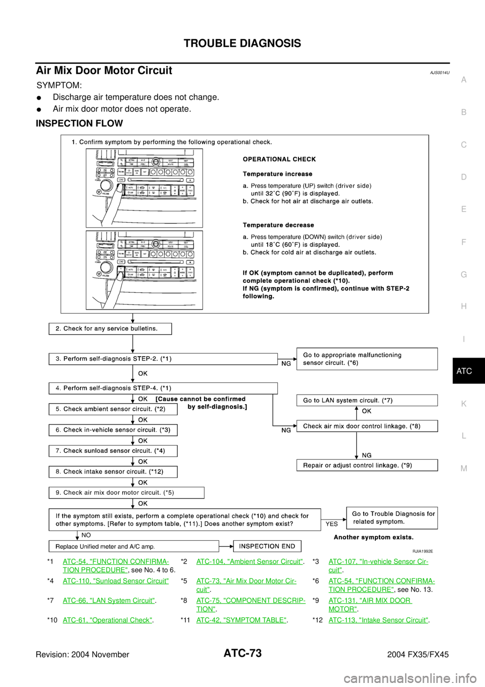
Air Mix Door Motor CircuitAJS0014U
SYMPTOM:
�Discharge air temperature does not change.
�Air mix door motor does not operate.
INSPECTION FLOW
*1ATC-54, "FUNCTION CONFIRMA-
TION PROCEDURE", see No. 4 to 6.*2ATC-104, "
Ambient Sensor Circuit".*3ATC-107, "In-vehicle Sensor Cir-
cuit".
*4ATC-110, "
Sunload Sensor Circuit"*5ATC-73, "Air Mix Door Motor Cir-
cuit".*6ATC-54, "
FUNCTION CONFIRMA-
TION PROCEDURE", see No. 13.
*7ATC-66, "
LAN System Circuit".*8ATC-75, "COMPONENT DESCRIP-
TION".*9ATC-131, "
AIR MIX DOOR
MOTOR".
*10ATC-61, "
Operational Check".*11ATC-42, "SYMPTOM TABLE".*12ATC-113, "Intake Sensor Circuit".
RJIA1992E
Page 506 of 4449
TROUBLE DIAGNOSIS
ATC-77
C
D
E
F
G
H
I
K
L
MA
B
AT C
Revision: 2004 November 2004 FX35/FX45
SYSTEM DESCRIPTION
Component Parts
Intake door control system components are:
�Unified meter and A/C amp.
�Intake door motor (LCU)
�A/C LAN system (PBR built-in mode door motor, air mix door motor and intake door motor)
�In-vehicle sensor
�Ambient sensor
�Sunload sensor
�Intake sensor
System Operation
The intake door control determines intake door position based on the ambient temperature, the intake air tem-
perature and the in-vehicle temperature. When the DEFROST, or OFF switches are pushed or A/C switch is
OFF, the unified meter and A/C amp. sets the intake door at the FRESH position.
Intake Door Control Specification
RJIA1786E
RJIA1787E