Page 3023 of 4449
![INFINITI FX35 2004 Service Manual FAX-14
[AWD]
FRONT DRIVE SHAFT
Revision: 2004 November 2004 FX35/FX45
INSTALLATION
�Refer to FAX-13, "Removal and Installation (Right Side)" for tightening torque. Install in the reverse order
of rem INFINITI FX35 2004 Service Manual FAX-14
[AWD]
FRONT DRIVE SHAFT
Revision: 2004 November 2004 FX35/FX45
INSTALLATION
�Refer to FAX-13, "Removal and Installation (Right Side)" for tightening torque. Install in the reverse order
of rem](/manual-img/42/57021/w960_57021-3022.png)
FAX-14
[AWD]
FRONT DRIVE SHAFT
Revision: 2004 November 2004 FX35/FX45
INSTALLATION
�Refer to FAX-13, "Removal and Installation (Right Side)" for tightening torque. Install in the reverse order
of removal.
NOTE:
Refer to component parts location and do not reuse non-reusable parts.
�Check the following item after service.
–Installation condition of wheel sensor harness.
�In order to prevent damage to front final drive assembly side oil
seal, first fit a protector onto oil seal before inserting drive shaft.
Slide drive shaft into slide joint and tap with a hammer to install
securely.
CAUTION:
Be sure to check that circular clip is securely fastened.
Disassembly and Assembly (Left Side)ADS000OP
DISASSEMBLY
Front Final Drive Assembly Side
1. Press drive shaft in a vice.
CAUTION:
When retaining shaft in a vice, always use copper or aluminum plates between vise and shaft.
2. Remove boot bands.
3. If plug needs to be removed, move boot to wheel side, and drive it out with a plastic hammer.
SDIA0593E
1. Plug 2. Housing 3. Snap ring
4. Spider assembly 5. Boot band 6. Boot
7. Shaft 8. Circular clip 9. Joint sub-assembly
SDIA1443E
Page 3034 of 4449
SERVICE DATA
FAX-25
[AWD]
C
E
F
G
H
I
J
K
L
MA
B
FA X
Revision: 2004 November 2004 FX35/FX45
SERVICE DATAPFP:00030
Wheel BearingADS000OR
Drive ShaftADS000OS
Tightening TorqueADS000OT
Axial end play 0.05 mm (0.002 in) or less
Joint type (Wheel side) (Transaxle side)
Grease quantity 95 − 115 g (3.35 − 4.06 oz)95 − 105 g (3.35 − 3.70 oz) (LH side)
11 3 − 123 g (3.99 − 4.34 oz) (RH side)
Boots installed length 136 mm (5.35 in)95 − 97 mm (3.74 − 3.82 in) (LH side)
157.8 − 159.8 mm (6.21 − 6.29 in) (RH side)
Drive shaft - Side flange 44.5 N·m (4.5 kg-m, 33 lb)
Hub lock nut 275 N·m (28 kg-m, 203 lb)
Page 3035 of 4449
FAX-26
[AWD]
SERVICE DATA
Revision: 2004 November 2004 FX35/FX45
Page 3036 of 4449

FFD-1
FRONT FINAL DRIVE
D DRIVELINE/AXLE
CONTENTS
C
E
F
G
H
I
J
K
L
M
SECTION FFD
A
B
FFD
Revision: 2004 November 2004 FX35/FX45
FRONT FINAL DRIVE
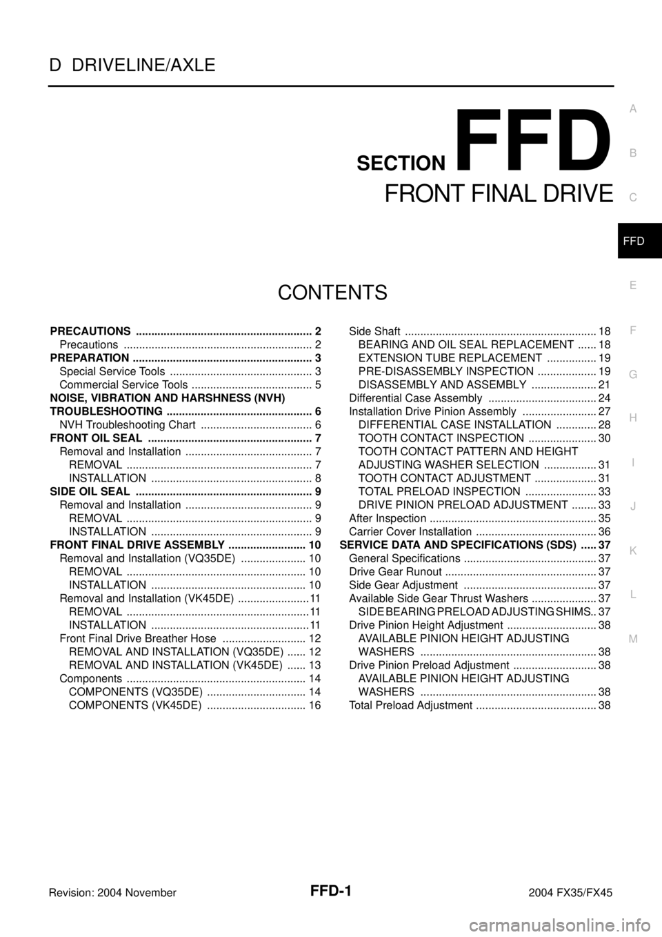
PRECAUTIONS .......................................................... 2
Precautions .............................................................. 2
PREPARATION ........................................................... 3
Special Service Tools ............................................... 3
Commercial Service Tools ........................................ 5
NOISE, VIBRATION AND HARSHNESS (NVH)
TROUBLESHOOTING ................................................ 6
NVH Troubleshooting Chart ..................................... 6
FRONT OIL SEAL ...................................................... 7
Removal and Installation .......................................... 7
REMOVAL ............................................................. 7
INSTALLATION ..................................................... 8
SIDE OIL SEAL .......................................................... 9
Removal and Installation .......................................... 9
REMOVAL ............................................................. 9
INSTALLATION ..................................................... 9
FRONT FINAL DRIVE ASSEMBLY .......................... 10
Removal and Installation (VQ35DE) ...................... 10
REMOVAL ........................................................... 10
INSTALLATION ................................................... 10
Removal and Installation (VK45DE) ........................ 11
REMOVAL ............................................................ 11
INSTALLATION .................................................... 11
Front Final Drive Breather Hose ............................ 12
REMOVAL AND INSTALLATION (VQ35DE) ....... 12
REMOVAL AND INSTALLATION (VK45DE) ....... 13
Components ........................................................... 14
COMPONENTS (VQ35DE) ................................. 14
COMPONENTS (VK45DE) ................................. 16Side Shaft ............................................................... 18
BEARING AND OIL SEAL REPLACEMENT ....... 18
EXTENSION TUBE REPLACEMENT ................. 19
PRE-DISASSEMBLY INSPECTION .................... 19
DISASSEMBLY AND ASSEMBLY ...................... 21
Differential Case Assembly .................................... 24
Installation Drive Pinion Assembly ......................... 27
DIFFERENTIAL CASE INSTALLATION .............. 28
TOOTH CONTACT INSPECTION ....................... 30
TOOTH CONTACT PATTERN AND HEIGHT
ADJUSTING WASHER SELECTION .................. 31
TOOTH CONTACT ADJUSTMENT ..................... 31
TOTAL PRELOAD INSPECTION ........................ 33
DRIVE PINION PRELOAD ADJUSTMENT ......... 33
After Inspection ....................................................... 35
Carrier Cover Installation ........................................ 36
SERVICE DATA AND SPECIFICATIONS (SDS) ...... 37
General Specifications ............................................ 37
Drive Gear Runout .................................................. 37
Side Gear Adjustment ............................................ 37
Available Side Gear Thrust Washers ...................... 37
SIDE BEARING PRELOAD ADJUSTING SHIMS ... 37
Drive Pinion Height Adjustment .............................. 38
AVAILABLE PINION HEIGHT ADJUSTING
WASHERS .......................................................... 38
Drive Pinion Preload Adjustment ............................ 38
AVAILABLE PINION HEIGHT ADJUSTING
WASHERS .......................................................... 38
Total Preload Adjustment ........................................ 38
Page 3038 of 4449

PREPARATION
FFD-3
C
E
F
G
H
I
J
K
L
MA
B
FFD
Revision: 2004 November 2004 FX35/FX45
PREPARATIONPFP:00002
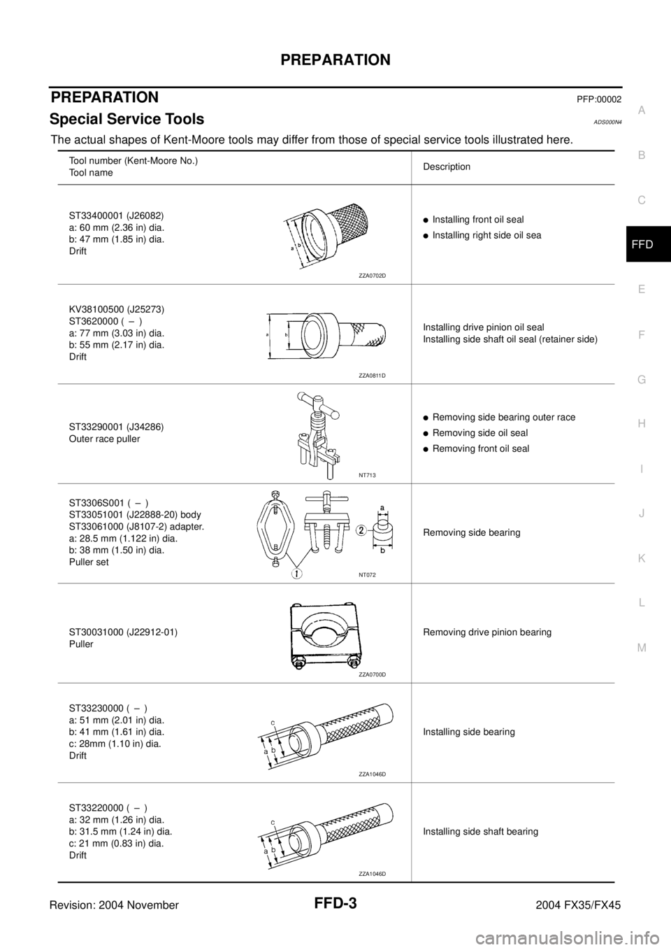
Special Service ToolsADS000N4
The actual shapes of Kent-Moore tools may differ from those of special service tools illustrated here.
Tool number (Kent-Moore No.)
Tool nameDescription
ST33400001 (J26082)
a: 60 mm (2.36 in) dia.
b: 47 mm (1.85 in) dia.
Drift
�Installing front oil seal
�Installing right side oil sea
KV38100500 (J25273)
ST3620000 ( – )
a: 77 mm (3.03 in) dia.
b: 55 mm (2.17 in) dia.
DriftInstalling drive pinion oil seal
Installing side shaft oil seal (retainer side)
ST33290001 (J34286)
Outer race puller
�Removing side bearing outer race
�Removing side oil seal
�Removing front oil seal
ST3306S001 ( – )
ST33051001 (J22888-20) body
ST33061000 (J8107-2) adapter.
a: 28.5 mm (1.122 in) dia.
b: 38 mm (1.50 in) dia.
Puller setRemoving side bearing
ST30031000 (J22912-01)
PullerRemoving drive pinion bearing
ST33230000 ( – )
a: 51 mm (2.01 in) dia.
b: 41 mm (1.61 in) dia.
c: 28mm (1.10 in) dia.
DriftInstalling side bearing
ST33220000 ( – )
a: 32 mm (1.26 in) dia.
b: 31.5 mm (1.24 in) dia.
c: 21 mm (0.83 in) dia.
DriftInstalling side shaft bearing
ZZA0702D
ZZA0811D
NT713
NT072
ZZA0700D
ZZA1046D
ZZA1046D
Page 3040 of 4449
PREPARATION
FFD-5
C
E
F
G
H
I
J
K
L
MA
B
FFD
Revision: 2004 November 2004 FX35/FX45
Commercial Service ToolsADS000N5
ST35321000 ( – )
a: 49 mm (1.93 in) dia.
b: 41 mm (1.61 in) dia.
DriftInstalling side bearing
KV40104000 ( – )
a: 85 mm (3.35 in) dia.
b: 65 mm (2.56 in) dia.
Drive pinion flange wrenchRemoving and installing drive pinion lock
nut
ST3127S000 (see J25765-A)
1. GG91030000
Torque wrench (J25765)
2. HT62940000 ( – )
Socket adapter (1/2″)
3. HT62900000 ( – )
Socket adapter (3/8″)
Preload gaugeInspecting pinion bearing preload and total
preload Tool number (Kent-Moore No.)
Tool nameDescription
ZZA1000D
NT659
NT124
Tool nameDescription
Power toolLoosening bolts and nuts
PBIC0190E
Page 3042 of 4449
FRONT OIL SEAL
FFD-7
C
E
F
G
H
I
J
K
L
MA
B
FFD
Revision: 2004 November 2004 FX35/FX45
FRONT OIL SEALPFP:38189
Removal and InstallationADS000N7
REMOVAL
1. Remove the front propeller shaft. Refer to PR-4, "REMOVAL" .
2. Put a matching mark on the end of the drive pinion correspond-
ing to the B position matching mark on the final drive companion
flange.
CAUTION:
�For matching mark, use paint. Never damage drive pin-
ion.
�The matching mark B on the final drive companion flange
indicates the maximum vertical runout position.
3. Using the drive pinion flange wrench.Remove drive pinion lock
nut with tool.
4. Remove the companion flange using puller (commercial service
tool)
5. Remove the front oil seal using outer race puller.
SDIA1609E
Tool number : KV40104000 ( – )
SDIA1647E
SDIA1642E
Tool number : ST33290001 (J34286)
SDIA1643E
Page 3043 of 4449
FFD-8
FRONT OIL SEAL
Revision: 2004 November 2004 FX35/FX45
INSTALLATION
1. Apply multi-purpose grease to sealing lips of the oil seal. Drive
the oil seal into the differential case using special service tool so
that the oil seal flush with the gear carrier end.
NOTE:
�When installing the front oil seal, be careful not to get it
inclined.
�Discard the old front oil seal. Always replace it with a new
one.
2. Install the companion flange while align the matching mark of
the drive pinion with the matching mark B of the companion
flange.
3. Apply oil to the drive pinion threads and the seating surface of
drive pinion lock nut.
4. Using the drive pinion flange wrench. Install drive pinion lock nut
with tool.
CAUTION:
Do not reuse the drive pinion lock nut. Always replace it
with a new one.
5. Install the front propeller shaft. Refer to PR-5, "
INSTALLATION"
.Tool number A : ST33400001 (J26082)
B : KV38102510 ( – )
SDIA1645E
SDIA1609E
Tool number : KV40104000 ( – )
SDIA1647E