Page 3053 of 4449
FFD-18
FRONT FINAL DRIVE ASSEMBLY
Revision: 2004 November 2004 FX35/FX45
Side ShaftADS000NN
BEARING AND OIL SEAL REPLACEMENT
1. Hold the extension tube retainer with commercial service tool,
then press out the side shaft using a press.
2. Remove the side shaft oil seal from the extension tube retainer
with a flat blade screwdriver.
3. Apply multi-purpose grease to the side shaft oil seal lips, the
install it into the extension tube retainer using special service
tool.
4. Support the new bearing inner race with special service tool,
then press the side shaft into the bearing using a press.
SDIA1628E
SDIA1629E
Tool number : ST19820000 ( – )
SDIA1630E
Tool number : ST30032000 ( – )
SDIA1631E
Page 3055 of 4449

FFD-20
FRONT FINAL DRIVE ASSEMBLY
Revision: 2004 November 2004 FX35/FX45
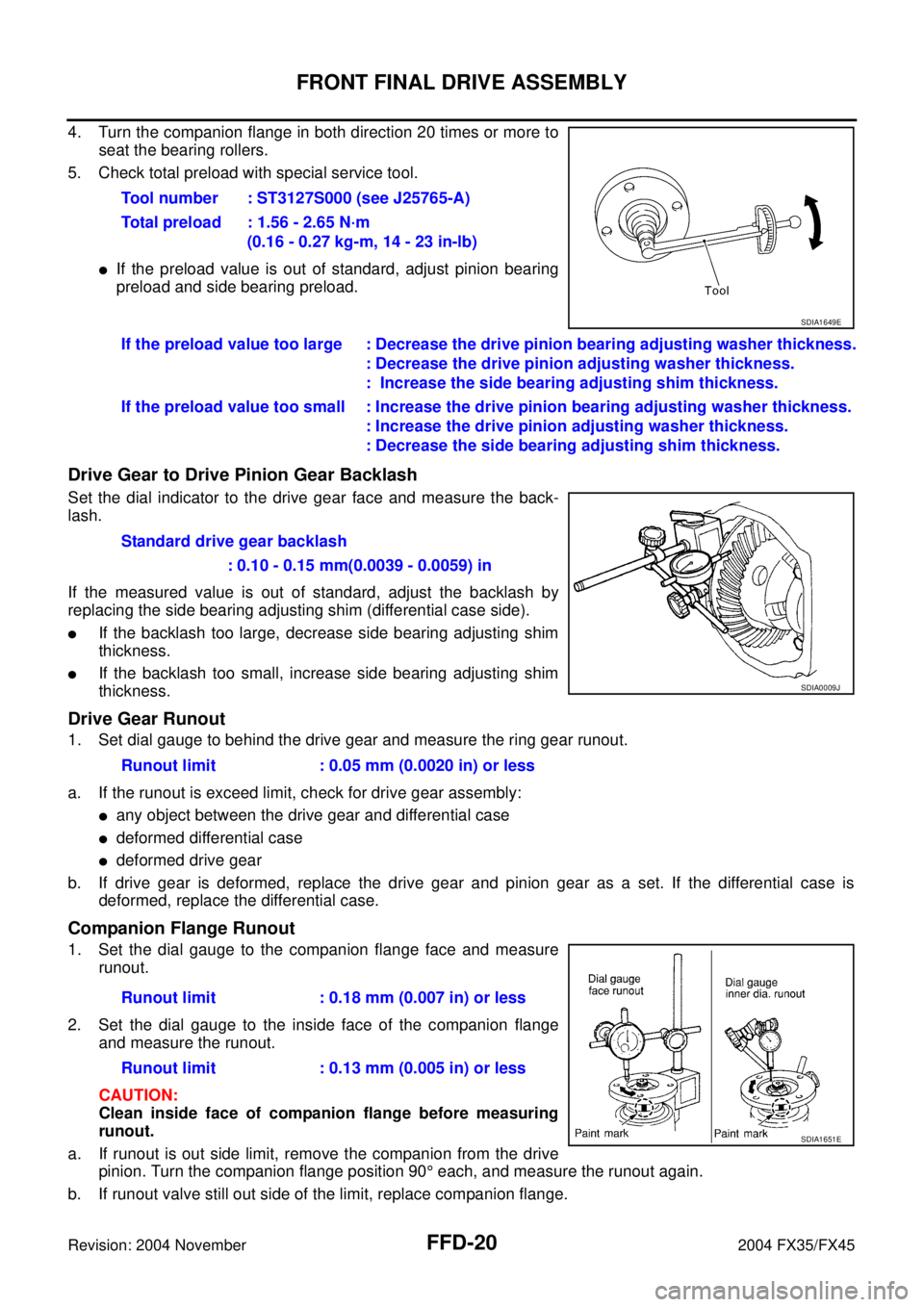
4. Turn the companion flange in both direction 20 times or more to
seat the bearing rollers.
5. Check total preload with special service tool.
�If the preload value is out of standard, adjust pinion bearing
preload and side bearing preload.
Drive Gear to Drive Pinion Gear Backlash
Set the dial indicator to the drive gear face and measure the back-
lash.
If the measured value is out of standard, adjust the backlash by
replacing the side bearing adjusting shim (differential case side).
�If the backlash too large, decrease side bearing adjusting shim
thickness.
�If the backlash too small, increase side bearing adjusting shim
thickness.
Drive Gear Runout
1. Set dial gauge to behind the drive gear and measure the ring gear runout.
a. If the runout is exceed limit, check for drive gear assembly:
�any object between the drive gear and differential case
�deformed differential case
�deformed drive gear
b. If drive gear is deformed, replace the drive gear and pinion gear as a set. If the differential case is
deformed, replace the differential case.
Companion Flange Runout
1. Set the dial gauge to the companion flange face and measure
runout.
2. Set the dial gauge to the inside face of the companion flange
and measure the runout.
CAUTION:
Clean inside face of companion flange before measuring
runout.
a. If runout is out side limit, remove the companion from the drive
pinion. Turn the companion flange position 90° each, and measure the runout again.
b. If runout valve still out side of the limit, replace companion flange.Tool number : ST3127S000 (see J25765-A)
Total preload : 1.56 - 2.65 N·m
(0.16 - 0.27 kg-m, 14 - 23 in-lb)
SDIA1649E
If the preload value too large : Decrease the drive pinion bearing adjusting washer thickness.
: Decrease the drive pinion adjusting washer thickness.
: Increase the side bearing adjusting shim thickness.
If the preload value too small : Increase the drive pinion bearing adjusting washer thickness.
: Increase the drive pinion adjusting washer thickness.
: Decrease the side bearing adjusting shim thickness.
Standard drive gear backlash
: 0.10 - 0.15 mm(0.0039 - 0.0059) in
SDIA0009J
Runout limit : 0.05 mm (0.0020 in) or less
Runout limit : 0.18 mm (0.007 in) or less
Runout limit : 0.13 mm (0.005 in) or less
SDIA1651E
Page 3068 of 4449

FRONT FINAL DRIVE ASSEMBLY
FFD-33
C
E
F
G
H
I
J
K
L
MA
B
FFD
Revision: 2004 November 2004 FX35/FX45
TOTAL PRELOAD INSPECTION
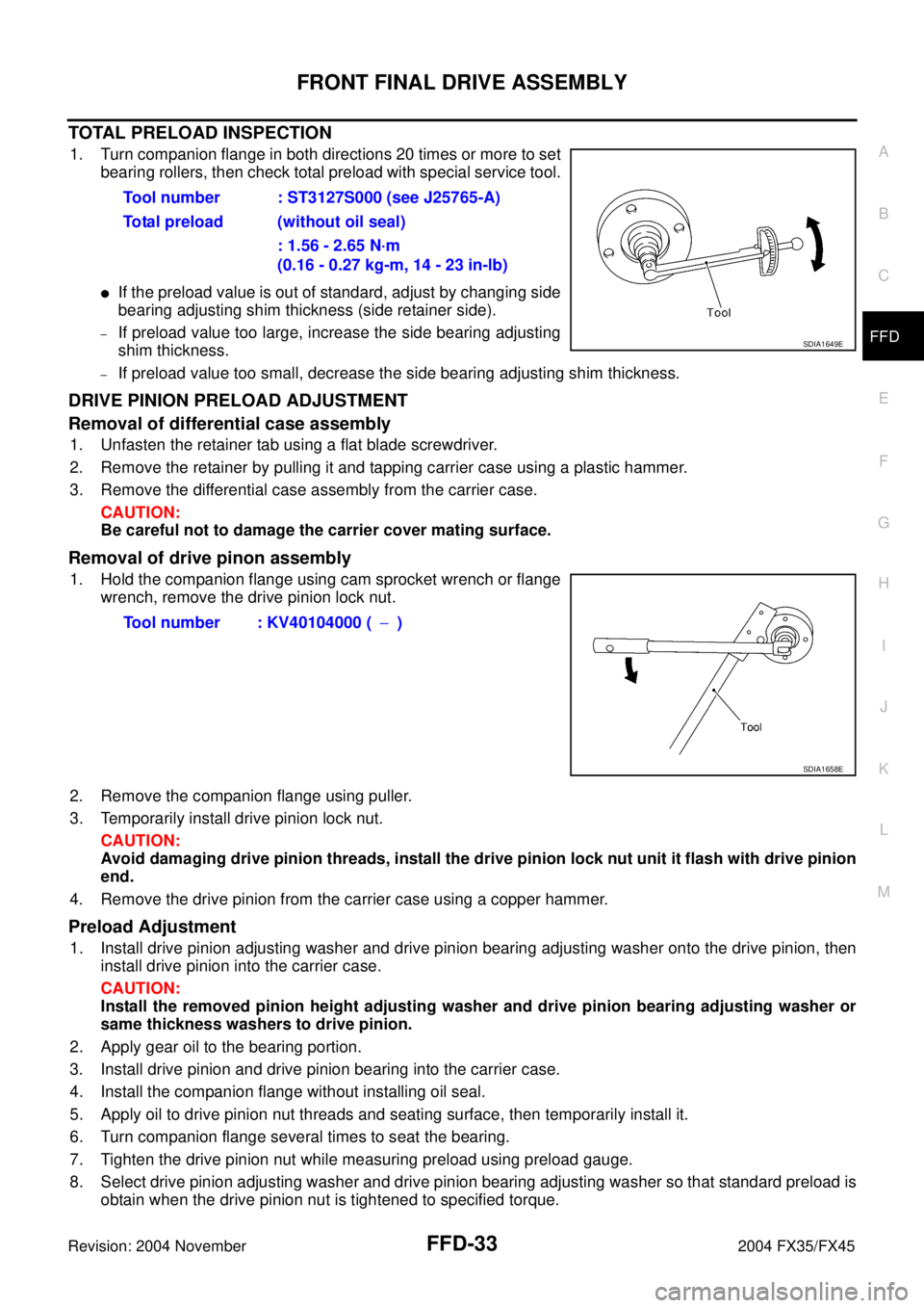
1. Turn companion flange in both directions 20 times or more to set
bearing rollers, then check total preload with special service tool.
�If the preload value is out of standard, adjust by changing side
bearing adjusting shim thickness (side retainer side).
–If preload value too large, increase the side bearing adjusting
shim thickness.
–If preload value too small, decrease the side bearing adjusting shim thickness.
DRIVE PINION PRELOAD ADJUSTMENT
Removal of differential case assembly
1. Unfasten the retainer tab using a flat blade screwdriver.
2. Remove the retainer by pulling it and tapping carrier case using a plastic hammer.
3. Remove the differential case assembly from the carrier case.
CAUTION:
Be careful not to damage the carrier cover mating surface.
Removal of drive pinon assembly
1. Hold the companion flange using cam sprocket wrench or flange
wrench, remove the drive pinion lock nut.
2. Remove the companion flange using puller.
3. Temporarily install drive pinion lock nut.
CAUTION:
Avoid damaging drive pinion threads, install the drive pinion lock nut unit it flash with drive pinion
end.
4. Remove the drive pinion from the carrier case using a copper hammer.
Preload Adjustment
1. Install drive pinion adjusting washer and drive pinion bearing adjusting washer onto the drive pinion, then
install drive pinion into the carrier case.
CAUTION:
Install the removed pinion height adjusting washer and drive pinion bearing adjusting washer or
same thickness washers to drive pinion.
2. Apply gear oil to the bearing portion.
3. Install drive pinion and drive pinion bearing into the carrier case.
4. Install the companion flange without installing oil seal.
5. Apply oil to drive pinion nut threads and seating surface, then temporarily install it.
6. Turn companion flange several times to seat the bearing.
7. Tighten the drive pinion nut while measuring preload using preload gauge.
8. Select drive pinion adjusting washer and drive pinion bearing adjusting washer so that standard preload is
obtain when the drive pinion nut is tightened to specified torque.Tool number : ST3127S000 (see J25765-A)
Total preload (without oil seal)
: 1.56 - 2.65 N·m
(0.16 - 0.27 kg-m, 14 - 23 in-lb)
SDIA1649E
Tool number : KV40104000 (−)
SDIA1658E
Page 3072 of 4449

SERVICE DATA AND SPECIFICATIONS (SDS)
FFD-37
C
E
F
G
H
I
J
K
L
MA
B
FFD
Revision: 2004 November 2004 FX35/FX45
SERVICE DATA AND SPECIFICATIONS (SDS)PFP:00030
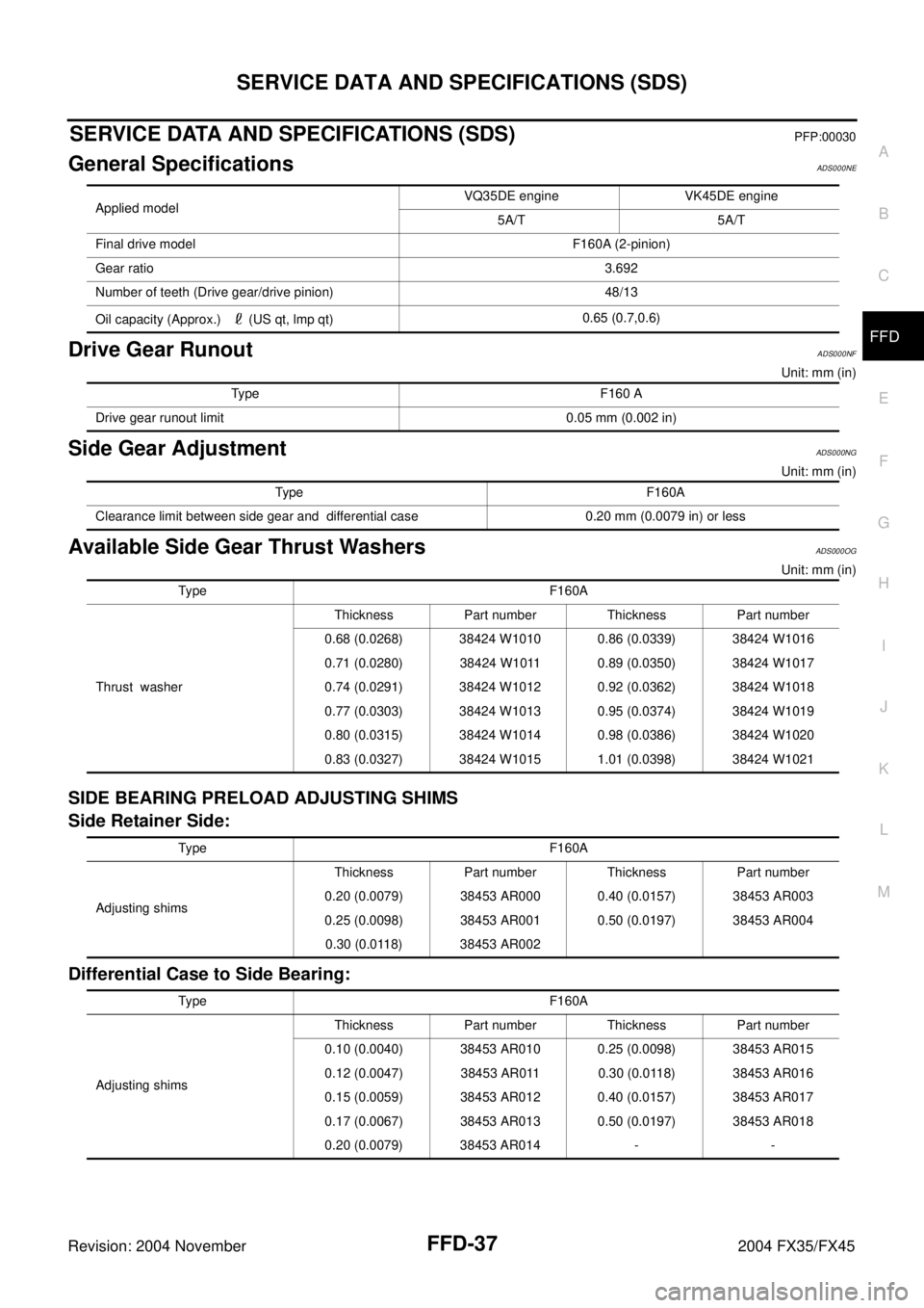
General SpecificationsADS000NE
Drive Gear RunoutADS000NF
Unit: mm (in)
Side Gear Adjustment ADS000NG
Unit: mm (in)
Available Side Gear Thrust WashersADS000OG
Unit: mm (in)
SIDE BEARING PRELOAD ADJUSTING SHIMS
Side Retainer Side:
Differential Case to Side Bearing:
Applied modelVQ35DE engine VK45DE engine
5A/T 5A/T
Final drive model F160A (2-pinion)
Gear ratio3.692
Number of teeth (Drive gear/drive pinion) 48/13
Oil capacity (Approx.) (US qt, lmp qt)0.65 (0.7,0.6)
Type F160 A
Drive gear runout limit 0.05 mm (0.002 in)
Type F16 0A
Clearance limit between side gear and differential case 0.20 mm (0.0079 in) or less
Type F16 0A
Thrust washerThickness Part number Thickness Part number
0.68 (0.0268) 38424 W1010 0.86 (0.0339) 38424 W1016
0.71 (0.0280) 38424 W1011 0.89 (0.0350) 38424 W1017
0.74 (0.0291) 38424 W1012 0.92 (0.0362) 38424 W1018
0.77 (0.0303) 38424 W1013 0.95 (0.0374) 38424 W1019
0.80 (0.0315) 38424 W1014 0.98 (0.0386) 38424 W1020
0.83 (0.0327) 38424 W1015 1.01 (0.0398) 38424 W1021
Type F16 0A
Adjusting shimsThickness Part number Thickness Part number
0.20 (0.0079) 38453 AR000 0.40 (0.0157) 38453 AR003
0.25 (0.0098) 38453 AR001 0.50 (0.0197) 38453 AR004
0.30 (0.0118) 38453 AR002
Type F16 0A
Adjusting shimsThickness Part number Thickness Part number
0.10 (0.0040) 38453 AR010 0.25 (0.0098) 38453 AR015
0.12 (0.0047) 38453 AR011 0.30 (0.0118) 38453 AR016
0.15 (0.0059) 38453 AR012 0.40 (0.0157) 38453 AR017
0.17 (0.0067) 38453 AR013 0.50 (0.0197) 38453 AR018
0.20 (0.0079) 38453 AR014 - -
Page 3073 of 4449

FFD-38
SERVICE DATA AND SPECIFICATIONS (SDS)
Revision: 2004 November 2004 FX35/FX45
Drive Pinion Height AdjustmentADS000NH
AVAILABLE PINION HEIGHT ADJUSTING WASHERS
Unit: mm (in)
Drive Pinion Preload AdjustmentADS000NI
AVAILABLE PINION HEIGHT ADJUSTING WASHERS
Unit: mm (in)
Total Preload AdjustmentADS000NK
Type F160A
Adjusting washersThickness Part number Thickness Part number
3.09 (0.1217) 38154 U1500 3.39 (0.1335) 38154 U1510
3.12 (0.1228) 38154 U1501 3.42 (0.1346) 38154 U1511
3.15 (0.1240) 38154 U1502 3.45 (0.1358) 38154U1512
3.18 (0.1252) 38154 U1503 3.48 (0.1370) 38154 U1513
3.21 (0.1264) 38154 U1504 3.51 (0.1382) 38154 U1514
3.24 (0.1276) 38154 U1505 3.54 (0.1394) 38154 U1515
3.27 (0.1283) 38154 U1506 3.57 (0.1406) 38154 U1516
3.30 (0.1299) 38154 U1507 3.60 (0.1429) 38154 U1517
3.33 (0.1323) 38154 U1508 3.63 (0.1429) 38154 U1518
3.36 (0.1323) 38154 U1509 3.66 (0.1441) 38154 U1519
Type F160A
Drive pinion preload without front oil seal 0.78 − 1.57 N·m (0.08 − 0.16 kg−m, 7 − 13 in-lb)
Type F160A
Adjusting washersThickness Part number Thickness Part number
3.81 (0.1500) 38125 61001 4.01 (0.1579) 38135 61001
3.83 (0.1508) 38126 61001 4.03 (0.1587) 38136 61001
3.85 (0.1516) 38127 61001 4.05 (0.1594) 38137 61001
3.87 (0.1524) 38128 61001 4.07 (0.1602) 38138 61001
3.89 (0.1531) 39129 61001 4.09 (0.1610) 38139 61001
3.91 (0.1539) 38130 61001 5.19 (0.2043) 38151 AR000
3.93 (0.1547) 38131 61001 5.49 (0.2161) 38151 AR001
3.95 (0.1555) 38132 61001 5.79 (0.2280) 38151 AR002
3.97 (0.1563) 38133 61001 6.09 (0.2398) 38151 AR003
3.99 (0.1571) 38134 61001 6.39 (0.2516) 38151 AR004
Type F160A
Total preload with oil seal 1.56 − 2.65 N·m (0.16 − 0.27 kg−m, 14 − 23 in-lb)
Drive gear to drive pinion backlash 0.10 − 0.15 mm (0.0039 − 0.0059 in)
Page 3074 of 4449

FL-1
FUEL SYSTEM
B ENGINE
CONTENTS
C
D
E
F
G
H
I
J
K
L
M
SECTION FL
A
FL
Revision: 2004 November 2004 FX35/FX45
FUEL SYSTEM
PREPARATION ........................................................... 2
Commercial Service Tool ......................................... 2
FUEL SYSTEM ........................................................... 3
Checking Fuel Lines ................................................. 3
General Precautions ................................................ 3
FUEL LEVEL SENSOR UNIT, FUEL FILTER AND
FUEL PUMP ASSEMBLY ........................................... 4
Removal and Installation .......................................... 4
REMOVAL ............................................................. 4
INSTALLATION ..................................................... 6INSPECTION AFTER INSTALLATION .................. 7
Disassembly and Assembly ...................................... 8
DISASSEMBLY ..................................................... 8
ASSEMBLY ........................................................... 9
FUEL TANK .............................................................. 10
Removal and Installation ........................................ 10
REMOVAL ........................................................... 10
INSTALLATION ................................................... 11
INSPECTION AFTER INSTALLATION ................ 11
SERVICE DATA AND SPECIFICATIONS (SDS) ...... 12
Standard and Limit .................................................. 12
Page 3075 of 4449
FL-2
PREPARATION
Revision: 2004 November 2004 FX35/FX45
PREPARATIONPFP:00002
Commercial Service ToolABS005YW
Tool nameDescription
Power toolLoosening bolts and nuts
PBIC0190E
Page 3085 of 4449
FL-12
SERVICE DATA AND SPECIFICATIONS (SDS)
Revision: 2004 November 2004 FX35/FX45
SERVICE DATA AND SPECIFICATIONS (SDS)PFP:00030
Standard and LimitABS005Z2
Fuel tank capacity
Approx. 90 (23-3/4 US gal, 19-3/4 Imp gal)