Page 2827 of 4449
![INFINITI FX35 2004 Service Manual EM-102
[VQ35DE]
CYLINDER HEAD
Revision: 2004 November 2004 FX35/FX45
d. Turn all bolts “90” degrees clockwise (angle tightening).
e. Turn all bolts “90” degrees clockwise again [target: 90 deg](/manual-img/42/57021/w960_57021-2826.png "INFINITI FX35 2004 Service Manual EM-102
[VQ35DE]
CYLINDER HEAD
Revision: 2004 November 2004 FX35/FX45
d. Turn all bolts “90” degrees clockwise (angle tightening).
e. Turn all bolts “90” degrees clockwise again [target: 90 deg")
EM-102
[VQ35DE]
CYLINDER HEAD
Revision: 2004 November 2004 FX35/FX45
d. Turn all bolts “90” degrees clockwise (angle tightening).
e. Turn all bolts “90” degrees clockwise again [target: 90 degrees
(angle tightening)].
CAUTION:
Check and confirm the tightening angle by using angle
wrench (SST) and cylinder head bolt wrench (commercial
service tool). Avoid judgment by visual inspection without
SST.
�Check tightening angle indicated on angle wrench (SST) indi-
cator plate.
4. After installing cylinder head, measure distance between front
end faces of cylinder block and cylinder head (left and right
banks).
�If measurement is outside the specified range, re-install cylin-
der head.
5. Perform steps in reverse order of removal for the following operations.
Disassembly and AssemblyABS004X9
PBIC0888E
Standard : 14.1 - 14.9 mm (0.555 - 0.587 in)
EMQ0662D
1. Valve lifter 2. Valve collet 3. Valve spring retainer
4. Valve spring 5. Valve oil seal 6. Valve spring seat
7. Valve guide 8. Spark plug 9. Spark plug tube
PBIC2308E
Page 2828 of 4449
![INFINITI FX35 2004 Service Manual CYLINDER HEAD
EM-103
[VQ35DE]
C
D
E
F
G
H
I
J
K
L
MA
EM
Revision: 2004 November 2004 FX35/FX45
DISASSEMBLY
1. Remove spark plug with spark plug wrench (commercial service tool).
2. Remove valve lifter](/manual-img/42/57021/w960_57021-2827.png "INFINITI FX35 2004 Service Manual CYLINDER HEAD
EM-103
[VQ35DE]
C
D
E
F
G
H
I
J
K
L
MA
EM
Revision: 2004 November 2004 FX35/FX45
DISASSEMBLY
1. Remove spark plug with spark plug wrench (commercial service tool).
2. Remove valve lifter")
CYLINDER HEAD
EM-103
[VQ35DE]
C
D
E
F
G
H
I
J
K
L
MA
EM
Revision: 2004 November 2004 FX35/FX45
DISASSEMBLY
1. Remove spark plug with spark plug wrench (commercial service tool).
2. Remove valve lifter.
�Mark position on valve lifter for assembly.
3. Remove valve collet.
�Compress valve spring with valve spring compressor, attach-
ment and adapter (SST). Remove valve collet with magnet
hand.
CAUTION:
When working, take care not to damage valve lifter holes.
4. Remove valve spring retainer and valve spring.
5. Push valve stem to combustion chamber side, and remove
valve.
�Inspect valve guide clearance before removal. Refer to EM-
105, "VALVE GUIDE CLEARANCE" .
�Mark position on valve for assembly.
6. Remove valve oil seals using valve oil seal puller (SST).
7. Remove valve spring seat.
8. If valve seat must be replaced, refer to EM-107, "
VALVE SEAT CONTACT" .
9. If valve guide must be replaced, refer to EM-105, "
VALVE GUIDE CLEARANCE" .
10. Remove spark plug tube, as necessary.
�Using a pair of pliers, pull spark plug tube out of cylinder head.
CAUTION:
�Take care not to damage cylinder head.
�Once removed, a spark plug tube will be deformed and cannot be reused. Do not remove it
unless absolutely necessary.
ASSEMBLY
1. When valve guide is removed, install it. Refer to EM-105, "VALVE GUIDE CLEARANCE" .
2. When valve seat is removed, install it. Refer to EM-107, "
VALVE SEAT CONTACT" .
3. Install valve oil seals.
�Install with valve oil seal drift (SST) to match dimension in
illustration.
4. Install valve spring seat.
10. Cylinder head (right bank) 11. Valve seat 12. Valve (EXH)
13. Valve (INT) 14. Cylinder head (left bank)
PBIC1803E
PBIC0884E
Height “H” (Without valve spring seat installed)
Intake and exhaust : 14.3 - 14.9 mm (0.563 - 0.587 in)
PBIC0802E
Page 2829 of 4449
![INFINITI FX35 2004 Service Manual EM-104
[VQ35DE]
CYLINDER HEAD
Revision: 2004 November 2004 FX35/FX45
5. Install the valves.
�Larger diameter valves are for intake side.
6. Install valve spring (uneven pitch type).
�Install smaller p](/manual-img/42/57021/w960_57021-2828.png "INFINITI FX35 2004 Service Manual EM-104
[VQ35DE]
CYLINDER HEAD
Revision: 2004 November 2004 FX35/FX45
5. Install the valves.
�Larger diameter valves are for intake side.
6. Install valve spring (uneven pitch type).
�Install smaller p")
EM-104
[VQ35DE]
CYLINDER HEAD
Revision: 2004 November 2004 FX35/FX45
5. Install the valves.
�Larger diameter valves are for intake side.
6. Install valve spring (uneven pitch type).
�Install smaller pitch end (paint mark) to cylinder head side
(valve spring seat side).
7. Install valve spring retainer.
8. Install valve collet.
�Compress valve spring with valve spring compressor, attach-
ment and adapter (SST). Install valve collet with magnet
hand.
CAUTION:
When working, take care not to damage valve lifter holes.
�Tap valve stem edge lightly with plastic hammer after installa-
tion to check its installed condition.
9. Install valve lifter.
10. Install spark plug tube.
�Press-fit spark plug tube following procedure below.
a. Remove old liquid gasket adhering to cylinder-head mounting
hole.
b. Apply liquid gasket to area within approximately 12 mm (0.47 in)
from edge of spark plug tube press-fit side.
Use Genuine RTV Silicone Sealant or equivalent. Refer to
GI-48, "
RECOMMENDED CHEMICAL PRODUCTS AND
SEALANTS" .
c. Using a drift, press-fit spark plug tube so that its height “H” is as
specified in the figure.
CAUTION:
�When press-fitting, take care not to deform spark plug tube.
�After press-fitting, wipe off liquid gasket protruding onto cylinder-head upper face.
11. Install spark plug.
Inspection After DisassemblyABS004XA
VALVE DIMENSIONS
�Check dimensions of each valve. For dimensions, refer to EM-
150, "Valve Dimensions" .
�If dimensions are out of the standard, replace valve.
SEM085D
PBIC1803E
Standard press-fit height “H”:
: 38.55 - 38.65 mm (1.5177 - 1.5217 in)
KBIA1248E
SEM188A
Page 2830 of 4449
![INFINITI FX35 2004 Service Manual CYLINDER HEAD
EM-105
[VQ35DE]
C
D
E
F
G
H
I
J
K
L
MA
EM
Revision: 2004 November 2004 FX35/FX45
VALVE GUIDE CLEARANCE
Valve Stem Diameter
Measure inner diameter of valve guide with inside micrometer.
V](/manual-img/42/57021/w960_57021-2829.png "INFINITI FX35 2004 Service Manual CYLINDER HEAD
EM-105
[VQ35DE]
C
D
E
F
G
H
I
J
K
L
MA
EM
Revision: 2004 November 2004 FX35/FX45
VALVE GUIDE CLEARANCE
Valve Stem Diameter
Measure inner diameter of valve guide with inside micrometer.
V")
CYLINDER HEAD
EM-105
[VQ35DE]
C
D
E
F
G
H
I
J
K
L
MA
EM
Revision: 2004 November 2004 FX35/FX45
VALVE GUIDE CLEARANCE
Valve Stem Diameter
Measure inner diameter of valve guide with inside micrometer.
Valve Guide Inner Diameter
Measure inner diameter of valve guide with inside micrometer.
Valve Guide Clearance
�(Valve guide clearance) = (Valve guide inner diameter) – (Valve stem diameter).
�If it exceeds the limit, replace valve guide and / or valve.
VALVE GUIDE REPLACEMENT
When valve guide is removed, replace with oversized (0.2 mm, 0.008 in) valve guide.
1. To remove valve guide, heat cylinder head to 110 to 130°C (230
to 266°F) by soaking in heated oil. Standard
Intake : 5.965 - 5.980 mm (0.2348 - 0.2354 in)
Exhaust : 5.955 - 5.970 mm (0.2344 - 0.2350 in)
SEM938C
Standard
Intake and
Exhaust: 6.000 - 6.018 mm (0.2362 - 0.2369 in)
Valve guide clearance:
Standard
Intake : 0.020 - 0.053 mm (0.0008 - 0.0021 in)
Exhaust : 0.030 - 0.063 mm (0.0012 - 0.0025 in)
Limit
Intake : 0.08 mm (0.003 in)
Exhaust : 0.09 mm (0.004 in)
SEM008A
Page 2831 of 4449
EM-106
[VQ35DE]
CYLINDER HEAD
Revision: 2004 November 2004 FX35/FX45
2. Drive out valve guide with a press [under a 20 kN (2 ton, 2.2 US
ton, 2.0 lmp ton) pressure] or hammer and suitable tool.
CAUTION:
Cylinder head contains heat. When working, wear protec-
tive equipment to avoid getting burned.
3. Using valve guide reamer, ream cylinder head valve guide hole.
4. Heat cylinder head to 110 to 130°C (230 to 266°F) by soaking in
heated oil.
5. Press valve guide from camshaft side to dimensions as in illus-
tration.
CAUTION:
Cylinder head contains heat. When working, wear protec-
tive equipment to avoid getting burned.
6. Using valve guide reamer, apply reamer finish to valve guide.
SEM931C
Valve guide hole diameter (for service parts):
Intake and exhaust
: 10.175 - 10.196 mm (0.4006 - 0.4014 in)
SEM932C
SEM008A
Projection “L”
Intake and exhaust
: 12.6 - 12.8 mm (0.496 - 0.504 in)
SEM950E
Standard:
Intake and exhaust
: 6.000 - 6.018 mm (0.2362 - 0.2369 in)
SEM932C
Page 2832 of 4449
![INFINITI FX35 2004 Service Manual CYLINDER HEAD
EM-107
[VQ35DE]
C
D
E
F
G
H
I
J
K
L
MA
EM
Revision: 2004 November 2004 FX35/FX45
VALVE SEAT CONTACT
�After confirming that the dimensions of valve guides and valves
are within specificat](/manual-img/42/57021/w960_57021-2831.png "INFINITI FX35 2004 Service Manual CYLINDER HEAD
EM-107
[VQ35DE]
C
D
E
F
G
H
I
J
K
L
MA
EM
Revision: 2004 November 2004 FX35/FX45
VALVE SEAT CONTACT
�After confirming that the dimensions of valve guides and valves
are within specificat")
CYLINDER HEAD
EM-107
[VQ35DE]
C
D
E
F
G
H
I
J
K
L
MA
EM
Revision: 2004 November 2004 FX35/FX45
VALVE SEAT CONTACT
�After confirming that the dimensions of valve guides and valves
are within specifications, perform this procedure.
�Apply prussian blue (or white lead) onto contacting surface of
valve seat to check the condition of the valve contact on the sur-
face.
�Check if the contact area band is continuous all around the cir-
cumference.
�If not, grind to adjust valve fitting and check again. If the contact-
ing surface still has NG conditions even after the re-check,
replace valve seat.
VALVE SEAT REPLACEMENT
When valve seat is removed, replace with oversized (0.5 mm, 0.020 in) valve seat.
1. Bore out old seat until it collapses. Boring should not continue beyond the bottom face of the seat recess
in cylinder head. Set the machine depth stop to ensure this.
CAUTION:
Prevent to scratch cylinder head by excessive boring.
2. Ream cylinder head recess diameter for service valve seat.
�Be sure to ream in circles concentric to the valve guide center.
This will enable valve to fit correctly.
3. Heat cylinder head to 110 to 130°C (230 to 266°F) by soaking in
heated oil.
4. Provide valve seats cooled well with dry ice. Force fit valve seat into cylinder head.
CAUTION:
�Avoid directly touching cold valve seats.
�Cylinder head contains heat. When working, wear protective equipment to avoid getting burned.
SBIA0322E
Oversize [0.5 mm (0.020 in)]
Intake: 38.500 - 38.516 mm (1.5157 - 1.5164 in)
Exhaust: 32.700 - 32.716 mm (1.2874 - 1.2880 in)
SEM795A
SEM008A
Page 2833 of 4449
![INFINITI FX35 2004 Service Manual EM-108
[VQ35DE]
CYLINDER HEAD
Revision: 2004 November 2004 FX35/FX45
5. Using valve seat cutter set (commercial service tool) or valve
seat grinder, finish seat to the specified dimensions.
CAUTION:
W](/manual-img/42/57021/w960_57021-2832.png "INFINITI FX35 2004 Service Manual EM-108
[VQ35DE]
CYLINDER HEAD
Revision: 2004 November 2004 FX35/FX45
5. Using valve seat cutter set (commercial service tool) or valve
seat grinder, finish seat to the specified dimensions.
CAUTION:
W")
EM-108
[VQ35DE]
CYLINDER HEAD
Revision: 2004 November 2004 FX35/FX45
5. Using valve seat cutter set (commercial service tool) or valve
seat grinder, finish seat to the specified dimensions.
CAUTION:
When using valve seat cutter, firmly grip the cutter handle
with both hands. Then, press on the contacting surface all
around the circumference to cut in a single drive. Improper
pressure on with cutter or cutting many different times may
result in stage valve seat.
Grind to obtain the dimensions indicated.
*1 : Diameter made by intersection point of conic angles 60°
and 90°
*2 : Diameter made by intersection point of conic angles
89.5° and 120°
6. Using compound, grind to adjust valve fitting.
7. Check for normal contact again.
VALVE SPRING SQUARENESS
�Set try square along the side of valve spring and rotate spring.
Measure the maximum clearance between the top face of spring
and try square.
�If it exceeds the limit, replace valve spring.
SEM934C
Standard:
D1 dia.: 35 mm (1.38 in)*
1
D2 dia.: 36.6 - 36.8 mm (1.441 - 1.449 in)*2
D3 dia.: 28.7 mm (1.130 in)*1
D4 dia.: 30.6 - 30.8 mm (1.205 - 1.213 in)*2
SBIA0531E
Limit : Less than 2.1 mm (0.083 in)
PBIC0080E
Page 2834 of 4449
CYLINDER HEAD
EM-109
[VQ35DE]
C
D
E
F
G
H
I
J
K
L
MA
EM
Revision: 2004 November 2004 FX35/FX45
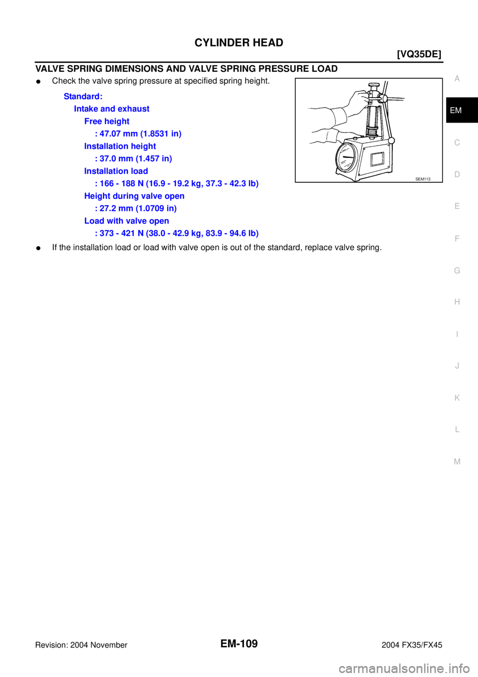
VALVE SPRING DIMENSIONS AND VALVE SPRING PRESSURE LOAD
�Check the valve spring pressure at specified spring height.
�If the installation load or load with valve open is out of the standard, replace valve spring.Standard:
Intake and exhaust
Free height
: 47.07 mm (1.8531 in)
Installation height
: 37.0 mm (1.457 in)
Installation load
: 166 - 188 N (16.9 - 19.2 kg, 37.3 - 42.3 lb)
Height during valve open
: 27.2 mm (1.0709 in)
Load with valve open
: 373 - 421 N (38.0 - 42.9 kg, 83.9 - 94.6 lb)
SEM113
![INFINITI FX35 2004 Service Manual EM-106
[VQ35DE]
CYLINDER HEAD
Revision: 2004 November 2004 FX35/FX45
2. Drive out valve guide with a press [under a 20 kN (2 ton, 2.2 US
ton, 2.0 lmp ton) pressure] or hammer and suitable tool.
CAUTIO](/manual-img/42/57021/w960_57021-2830.png "INFINITI FX35 2004 Service Manual EM-106
[VQ35DE]
CYLINDER HEAD
Revision: 2004 November 2004 FX35/FX45
2. Drive out valve guide with a press [under a 20 kN (2 ton, 2.2 US
ton, 2.0 lmp ton) pressure] or hammer and suitable tool.
CAUTIO")