Page 2848 of 4449
CYLINDER BLOCK
EM-123
[VQ35DE]
C
D
E
F
G
H
I
J
K
L
MA
EM
Revision: 2004 November 2004 FX35/FX45
7. Drain engine coolant by removing water drain plugs from cylin-
der block both sides at “B” and “C” and cylinder block front side
at “A” as shown in the figure.
8. Remove cylinder head. Refer to EM-98, "
CYLINDER HEAD" .
9. Remove knock sensor.
CAUTION:
Carefully handle sensor avoiding shocks.
10. Remove drive plate with power tool. Fix crankshaft with a ring gear stopper [SST: KV1011770 (J-44716)],
and remove mounting bolts.
�Loosen mounting bolts in diagonal order.
CAUTION:
�Do not disassemble drive plate.
�Never place drive plate with signal plate facing down.
�When handling signal plate, take care not to damage or
scratch it.
�Handle signal plate in a manner that prevents it from
becoming magnetized.
11. Remove pilot converter using pilot bushing puller (SST) or suit-
able tool as necessary.
PBIC2610E
SEM760G
SEM005G
Page 2849 of 4449
![INFINITI FX35 2004 Service Manual EM-124
[VQ35DE]
CYLINDER BLOCK
Revision: 2004 November 2004 FX35/FX45
12. Use a seal cutter (SST) to cut away liquid gasket and remove
rear oil seal retainer.
CAUTION:
�Be careful not to damage mounti](/manual-img/42/57021/w960_57021-2848.png "INFINITI FX35 2004 Service Manual EM-124
[VQ35DE]
CYLINDER BLOCK
Revision: 2004 November 2004 FX35/FX45
12. Use a seal cutter (SST) to cut away liquid gasket and remove
rear oil seal retainer.
CAUTION:
�Be careful not to damage mounti")
EM-124
[VQ35DE]
CYLINDER BLOCK
Revision: 2004 November 2004 FX35/FX45
12. Use a seal cutter (SST) to cut away liquid gasket and remove
rear oil seal retainer.
CAUTION:
�Be careful not to damage mounting surface.
�If rear oil seal retainer is removed, replace it with a new
one.
NOTE:
Rear oil seal and retainer make up a single part and are
removed as an assembly.
13. Remove baffle plate from main bearing beam (2WD model).
14. Remove piston and connecting rod assembly.
�Before removing piston and connecting rod assembly, check
connecting rod side clearance. Refer to EM-136, "
CONNECT-
ING ROD SIDE CLEARANCE" .
a. Position crankshaft pin corresponding to connecting rod to be
removed onto the bottom dead center.
b. Remove connecting rod cap.
c. Using a hammer handle or similar tool, push piston and connect-
ing rod assembly out to cylinder head side.
15. Remove connecting rod bearings from connecting rod and con-
necting rod cap.
CAUTION:
When removing them, note the installation position. Keep them in the correct order.
16. Remove piston rings form piston.
�Use a piston ring expander (commercial service tool).
CAUTION:
�When removing piston rings, be careful not to damage
piston.
�Be careful not to damage piston rings by expanding
them excessively.
17. Remove piston from connecting rod as follows.
a. Using a snap ring pliers, remove snap ring.
SEM830E
EMQ0191D
PBIC0087E
PBIC0088E
Page 2850 of 4449
CYLINDER BLOCK
EM-125
[VQ35DE]
C
D
E
F
G
H
I
J
K
L
MA
EM
Revision: 2004 November 2004 FX35/FX45
b. Heat piston to 60 to 70°C (140 to 158°F) with industrial use drier
or equivalent.
c. Push out piston pin with stick of outer diameter approximately 20
mm (0.79 in).
18. Remove main bearing cap bolt.
NOTE:
Use TORX socket (size E14).
�Before loosening main bearing cap bolts, measure crankshaft
end play. Refer to EM-136, "
CRANKSHAFT END PLAY" .
�Loosen them in the numerical order shown in the figure in
several different steps.
19. Remove main bearing beam.
20. Remove main bearing cap.
�Using main bearing cap bolts, remove main bearing cap while
shaking it back-and-forth.
21. Remove crankshaft.
22. Remove main bearings and thrust bearings from cylinder block
and main bearing cap.
CAUTION:
Identify installation positions, and store them without mix-
ing them up.
23. Remove oil jet.
PBIC0089E
PBIC0262E
PBIC0909E
PBIC0881E
EMQ0195D
Page 2851 of 4449
![INFINITI FX35 2004 Service Manual EM-126
[VQ35DE]
CYLINDER BLOCK
Revision: 2004 November 2004 FX35/FX45
ASSEMBLY
1. Fully air-blow engine coolant and engine oil passages in cylinder block, cylinder bore and crankcase to
remove any for](/manual-img/42/57021/w960_57021-2850.png "INFINITI FX35 2004 Service Manual EM-126
[VQ35DE]
CYLINDER BLOCK
Revision: 2004 November 2004 FX35/FX45
ASSEMBLY
1. Fully air-blow engine coolant and engine oil passages in cylinder block, cylinder bore and crankcase to
remove any for")
EM-126
[VQ35DE]
CYLINDER BLOCK
Revision: 2004 November 2004 FX35/FX45
ASSEMBLY
1. Fully air-blow engine coolant and engine oil passages in cylinder block, cylinder bore and crankcase to
remove any foreign material.
CAUTION:
Use a goggles to protect your eye.
2. Install each water drain plug to cylinder block as shown in the
figure.
�Apply liquid gasket to the thread of water drain plugs.
Use Genuine RTV Silicone Sealant or equivalent. Refer to
GI-48, "
RECOMMENDED CHEMICAL PRODUCTS AND
SEALANTS" .
3. Install each plug to cylinder block as shown in the figure if
removed.
�Apply liquid gasket to the thread of plugs and install plugs with
new gaskets.
Use Genuine High Strength Thread Locking Sealant or
equivalent. Refer to GI-48, "
RECOMMENDED CHEMICAL
PRODUCTS AND SEALANTS" .
Use Genuine RTV Silicone Sealant or equivalent. Refer to GI-48, "
RECOMMENDED CHEMICAL
PRODUCTS AND SEALANTS" .
4. Install oil jet.
�Insert oil jet dowel pin into cylinder block dowel pin hole, and
tighten mounting bolts.Water drain plug (front) “A”:
: 9.8 N·m (1.0 kg-m, 87 in-lb)
Water drain plug (RH) “B”:
: 19.6 N·m (2.0 kg-m, 14 ft-lb)
Water drain plug (LH) “C”:
: 19.6 N·m (2.0 kg-m, 14 ft-lb)
Plug (RH) “D”:
: 12.3 N·m (1.3 kg-m, 9 ft-lb)
Plug (rear) “E”:
: 62 N·m (6.3 kg-m, 46 ft-lb)
Plug (LH) “F”:
: 62 N·m (6.3 kg-m, 46 ft-lb)
PBIC2610E
PBIC0898E
Page 2852 of 4449
![INFINITI FX35 2004 Service Manual CYLINDER BLOCK
EM-127
[VQ35DE]
C
D
E
F
G
H
I
J
K
L
MA
EM
Revision: 2004 November 2004 FX35/FX45
5. Install main bearings and thrust bearings.
a. Remove dust, dirt, and engine oil on the bearing mating](/manual-img/42/57021/w960_57021-2851.png "INFINITI FX35 2004 Service Manual CYLINDER BLOCK
EM-127
[VQ35DE]
C
D
E
F
G
H
I
J
K
L
MA
EM
Revision: 2004 November 2004 FX35/FX45
5. Install main bearings and thrust bearings.
a. Remove dust, dirt, and engine oil on the bearing mating")
CYLINDER BLOCK
EM-127
[VQ35DE]
C
D
E
F
G
H
I
J
K
L
MA
EM
Revision: 2004 November 2004 FX35/FX45
5. Install main bearings and thrust bearings.
a. Remove dust, dirt, and engine oil on the bearing mating sur-
faces of cylinder block and main bearing cap.
b. Install thrust bearings to the both sides of No. 3 journal housing
on cylinder block and main bearing cap.
�Install thrust bearings with the oil groove facing to the crank-
shaft arm (outside).
�Install bearing with a projection on one end on cylinder block,
and bearing with a projection at center on cap. Align each pro-
jection with mating notch.
c. Install main bearings paying attention to the direction.
�Main bearing with an oil hole and groove goes on cylinder
block. The one without them goes on main bearing cap.
�Before installing bearings, apply engine oil to the bearing sur-
face (inside). Do not apply engine oil to the back surface, but
thoroughly clean it.
�When installing, align the bearing stopper to the notch.
�Ensure the oil holes on cylinder block and those on the corre-
sponding bearing are aligned.
6. Install crankshaft to cylinder block.
�While turning crankshaft by hand, make sure it turns
smoothly.
7. Install main bearing cap.
�Main bearing caps are identified by identification mark cast on
them. For installation, face front mark to front side.
NOTE:
Main bearing cap cannot be replaced as a single part,
because it is machined together with cylinder block.
8. Install main bearing beam.
�Install main bearing beam with front mark facing downward
(oil pan side).
�Install main bearing beam with front mark facing front of
engine.
9. Inspect outer diameter of main bearing cap bolt. Refer to EM-
144, "MAIN BEARING CAP BOLT OUTER DIAMETER" .
10. Install main bearing cap bolt.
a. Apply new engine oil to threads and seat surfaces of mounting
bolts.
b. Tighten bolts in numerical order with tightening torque in several
different steps.
PBIC0807E
SEM175F
SEM456G
PBIC0881E
: 35.3 N·m (3.6 kg-m, 26 ft-lb)
SEM851E
Page 2853 of 4449
![INFINITI FX35 2004 Service Manual EM-128
[VQ35DE]
CYLINDER BLOCK
Revision: 2004 November 2004 FX35/FX45
c. Turn all bolts another “90” degrees clockwise (Angle tightening).
CAUTION:
Use an angle wrench [SST: KV10112100 (BT8653-A)]](/manual-img/42/57021/w960_57021-2852.png "INFINITI FX35 2004 Service Manual EM-128
[VQ35DE]
CYLINDER BLOCK
Revision: 2004 November 2004 FX35/FX45
c. Turn all bolts another “90” degrees clockwise (Angle tightening).
CAUTION:
Use an angle wrench [SST: KV10112100 (BT8653-A)]")
EM-128
[VQ35DE]
CYLINDER BLOCK
Revision: 2004 November 2004 FX35/FX45
c. Turn all bolts another “90” degrees clockwise (Angle tightening).
CAUTION:
Use an angle wrench [SST: KV10112100 (BT8653-A)] to
check tightening angle. Do not make judgment by visual
inspection.
�After installing mounting bolts, make sure that crankshaft can
be rotated smoothly by hand.
�Check crankshaft end play. Refer to EM-136, "CRANKSHAFT
END PLAY" .
11. Inspect outer diameter of connecting rod bolt. Refer to EM-144,
"CONNECTING ROD BOLT OUTER DIAMETER" .
12. Install piston to connecting rod.
a. Using a snap ring pliers (commercial service tool), install a new snap ring to the groove of the piston rear
side.
�Insert it fully into groove to install.
b. Install piston to connecting rod.
�Using an industrial drier or similar tool, heat piston until piston pin can be pushed in by hand without
excess force [approx. 60 to 70 °C (140 to 158 °F)]. From the front to the rear, insert piston pin into pis-
ton and connecting rod.
�Assemble so that the front mark on the piston crown and the
cylinder number on connecting rod are positioned as shown in
the figure.
c. Install a new snap ring to the groove of the piston front side.
�Insert it fully into groove to install.
�After installing, make sure connecting rod moves smoothly.
13. Using a piston ring expander (commercial service tool), install piston rings.
CAUTION:
Be careful not to damage piston.
�If there is stamped mark on ring, mount it with marked side
up.
NOTE:
If there is no stamp on ring, no specific orientation is required
for installation.
�Position each ring with the gap as shown in the figure refer-
ring to the piston front mark.
PBIC0921E
SEM838F
Stamped mark:
To p r i n g : —
Second ring : “R”
SEM757G
PBIC0808E
Page 2854 of 4449
![INFINITI FX35 2004 Service Manual CYLINDER BLOCK
EM-129
[VQ35DE]
C
D
E
F
G
H
I
J
K
L
MA
EM
Revision: 2004 November 2004 FX35/FX45
14. Install connecting rod bearings to connecting rod and connect-
ing rod cap.
�When installing connect](/manual-img/42/57021/w960_57021-2853.png "INFINITI FX35 2004 Service Manual CYLINDER BLOCK
EM-129
[VQ35DE]
C
D
E
F
G
H
I
J
K
L
MA
EM
Revision: 2004 November 2004 FX35/FX45
14. Install connecting rod bearings to connecting rod and connect-
ing rod cap.
�When installing connect")
CYLINDER BLOCK
EM-129
[VQ35DE]
C
D
E
F
G
H
I
J
K
L
MA
EM
Revision: 2004 November 2004 FX35/FX45
14. Install connecting rod bearings to connecting rod and connect-
ing rod cap.
�When installing connecting rod bearings, apply engine oil to
the bearing surface (inside). Do not apply engine oil to the
back surface, but thoroughly clean it.
�When installing, align connecting rod bearing stopper protru-
sion with the cutout of connecting rod to install.
�Check the oil hole on connecting rod and that on the corre-
sponding bearing are aligned.
15. Install piston and connecting rod assembly to crankshaft.
�Position crankshaft pin corresponding to connecting rod to be
installed onto the bottom dead center.
�Apply engine oil sufficiently to cylinder bore, piston and crank-
shaft pin.
�Match cylinder position with the cylinder number on connect-
ing rod to install.
�Using a piston ring compressor (SST) or suitable tool, install
piston with the front mark on the piston crown facing the front
of engine.
CAUTION:
Be careful not to damage cylinder wall and crankshaft pin, resulting from an interference of con-
necting rod big end.
16. Install connecting rod cap.
�Match the stamped cylinder number marks on connecting rod
with those on cap to install.
�Be sure that front mark on connecting rod cap is facing front
of engine.
17. Tighten connecting rod bolt as follows.
a. Apply engine oil to the threads and seats of connecting rod
bolts.
b. Tighten bolts.
c. Then tighten all bolts “90” degrees clockwise (Angle tightening).
CAUTION:
Always use an angle wrench [SST: KV10112100 (BT8653-
A)]. Avoid tightening based on visual check alone.
�After tightening bolt, make sure that the crankshaft rotates
smoothly.
�Check the connecting rod side clearance. Refer to EM-136, "CONNECTING ROD SIDE CLEARANCE"
18. Install baffle plate to main bearing beam.
PBIC0266E
SEM620
PBIC0809E
: 19.6 N·m (2.0 kg-m, 14 ft-lb)
SEM953E
Page 2855 of 4449
EM-130
[VQ35DE]
CYLINDER BLOCK
Revision: 2004 November 2004 FX35/FX45
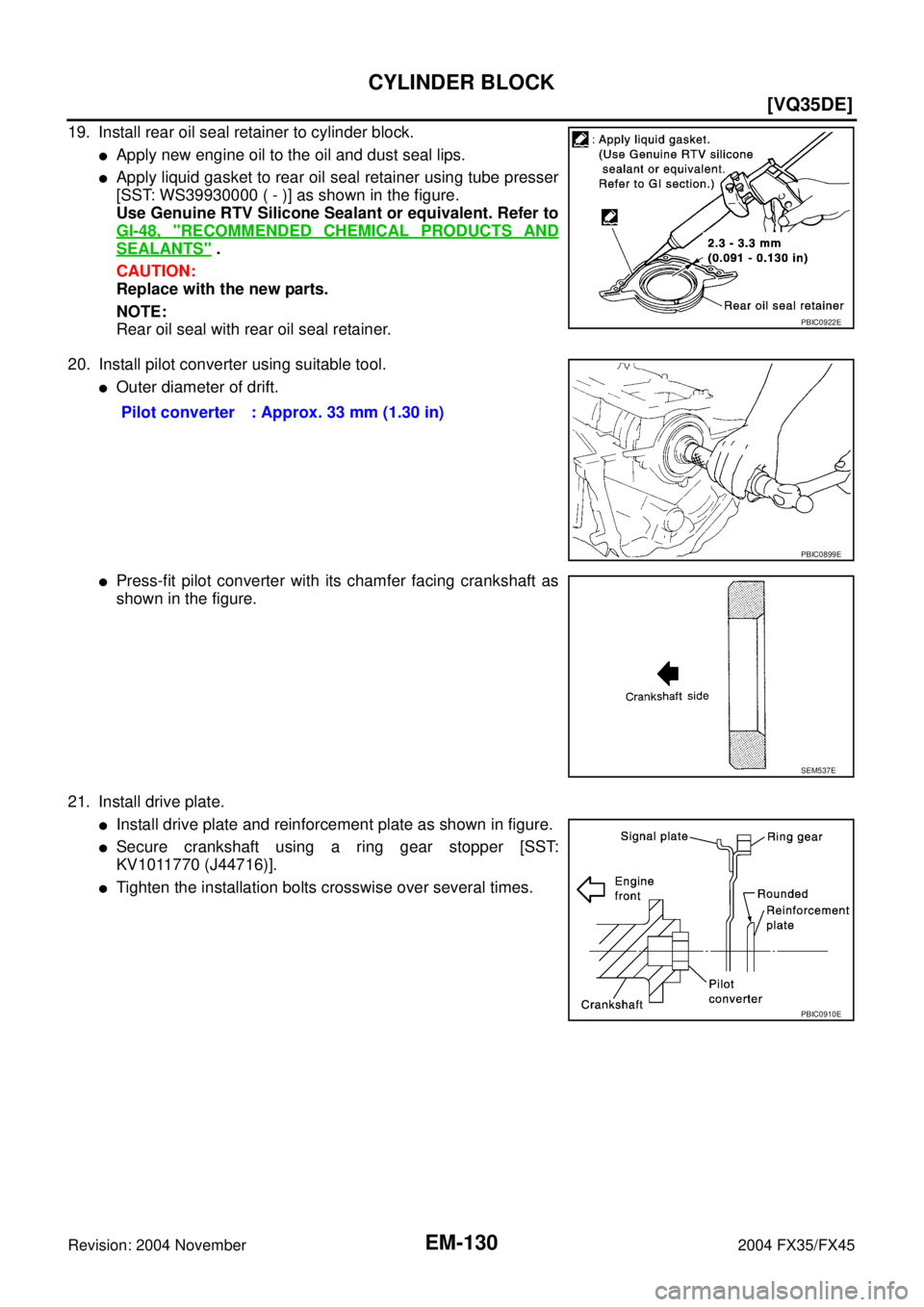
19. Install rear oil seal retainer to cylinder block.
�Apply new engine oil to the oil and dust seal lips.
�Apply liquid gasket to rear oil seal retainer using tube presser
[SST: WS39930000 ( - )] as shown in the figure.
Use Genuine RTV Silicone Sealant or equivalent. Refer to
GI-48, "
RECOMMENDED CHEMICAL PRODUCTS AND
SEALANTS" .
CAUTION:
Replace with the new parts.
NOTE:
Rear oil seal with rear oil seal retainer.
20. Install pilot converter using suitable tool.
�Outer diameter of drift.
�Press-fit pilot converter with its chamfer facing crankshaft as
shown in the figure.
21. Install drive plate.
�Install drive plate and reinforcement plate as shown in figure.
�Secure crankshaft using a ring gear stopper [SST:
KV1011770 (J44716)].
�Tighten the installation bolts crosswise over several times.
PBIC0922E
Pilot converter : Approx. 33 mm (1.30 in)
PBIC0899E
SEM537E
PBIC0910E
![INFINITI FX35 2004 Service Manual CYLINDER BLOCK
EM-123
[VQ35DE]
C
D
E
F
G
H
I
J
K
L
MA
EM
Revision: 2004 November 2004 FX35/FX45
7. Drain engine coolant by removing water drain plugs from cylin-
der block both sides at “B” and �](/manual-img/42/57021/w960_57021-2847.png "INFINITI FX35 2004 Service Manual CYLINDER BLOCK
EM-123
[VQ35DE]
C
D
E
F
G
H
I
J
K
L
MA
EM
Revision: 2004 November 2004 FX35/FX45
7. Drain engine coolant by removing water drain plugs from cylin-
der block both sides at “B” and �")
![INFINITI FX35 2004 Service Manual CYLINDER BLOCK
EM-125
[VQ35DE]
C
D
E
F
G
H
I
J
K
L
MA
EM
Revision: 2004 November 2004 FX35/FX45
b. Heat piston to 60 to 70°C (140 to 158°F) with industrial use drier
or equivalent.
c. Push out pisto](/manual-img/42/57021/w960_57021-2849.png "INFINITI FX35 2004 Service Manual CYLINDER BLOCK
EM-125
[VQ35DE]
C
D
E
F
G
H
I
J
K
L
MA
EM
Revision: 2004 November 2004 FX35/FX45
b. Heat piston to 60 to 70°C (140 to 158°F) with industrial use drier
or equivalent.
c. Push out pisto")