Page 2888 of 4449
PREPARATION
EM-163
[VK45DE]
C
D
E
F
G
H
I
J
K
L
MA
EM
Revision: 2004 November 2004 FX35/FX45KV10114700
(J38139)
Main bearing cap removerRemoving crankshaft main bearing cap
KV10107902
(J38959)
Valve oil seal pullerRemoving valve oil seal
KV10115600
(J38958)
Valve oil seal driftInstalling valve oil seal
Use side A.
a: 20 (0.79) dia. d: 8 (0.31) dia.
b: 13 (0.51) dia. e: 10.7 (0.421)
c: 10.3 (0.406) dia. f: 5 (0.20)
Unit: mm (in)
EM03470000
(J8037)
Piston ring compressorInstalling piston assembly into cylinder bore
ST16610001
(J23907)
Pilot bushing pullerRemoving crankshaft pilot converter
WS39930000
(—)
Tube presserPressing the tube of liquid gasket Tool number
(Kent-Moore No.)
Tool nameDescription
ZZA0023D
S-NT011
S-NT603
S-NT044
S-NT045
S-NT052
Page 2889 of 4449
EM-164
[VK45DE]
PREPARATION
Revision: 2004 November 2004 FX35/FX45
Commercial Service ToolsABS006I3
—
(J-45476)
Ring gear stopperRemoving and installing crankshaft pulley
—
(J-45488)
Quick connector releaseRemoving fuel tube quick connectors in
engine room
(Available in SEC. 164 of PARTS CATALOG:
Part No. 16441 6N210) Tool number
(Kent-Moore No.)
Tool nameDescription
PBIC1655E
PBIC0198E
(Kent-Moore No.)
Tool nameDescription
Power toolLoosening bolts and nuts
Spark plug wrench Removing and installing spark plug
Manual lift table caddy Removing and installing engine
(J24239-01)
Cylinder head bolt wrenchLoosening and tightening cylinder head bolt,
and use with angle wrench [SST:
KV10112100 (BT8653-A)]
a: 13 (0.51) dia.
b: 12 (0.47)
c: 10 (0.39)
Unit: mm (in)
PBIC0190E
S-NT047
ZZA1210D
NT583
Page 2892 of 4449
![INFINITI FX35 2004 Service Manual NOISE, VIBRATION AND HARSHNESS (NVH) TROUBLESHOOTING
EM-167
[VK45DE]
C
D
E
F
G
H
I
J
K
L
MA
EM
Revision: 2004 November 2004 FX35/FX45
Use the Chart Below to Help You Find the Cause of the Symptom.ABS0](/manual-img/42/57021/w960_57021-2891.png "INFINITI FX35 2004 Service Manual NOISE, VIBRATION AND HARSHNESS (NVH) TROUBLESHOOTING
EM-167
[VK45DE]
C
D
E
F
G
H
I
J
K
L
MA
EM
Revision: 2004 November 2004 FX35/FX45
Use the Chart Below to Help You Find the Cause of the Symptom.ABS0")
NOISE, VIBRATION AND HARSHNESS (NVH) TROUBLESHOOTING
EM-167
[VK45DE]
C
D
E
F
G
H
I
J
K
L
MA
EM
Revision: 2004 November 2004 FX35/FX45
Use the Chart Below to Help You Find the Cause of the Symptom.ABS006I5
1. Locate the area where noise occurs.
2. Confirm the type of noise.
3. Specify the operating condition of engine.
4. Check specified noise source.
If necessary, repair or replace these parts.
A: Closely related B: Related C: Sometimes related —: Not relatedLocation
of noiseTy p e o f
noiseOperating condition of engine
Source of
noiseCheck itemRefer-
ence page Before
warm-
upAfter
warm-
upWhen
start-
ingWhen
idlingWhen
racingWhile
driving
Top of
engine
Rocker
cover
Cylinder
headTicking or
clickingC A — A B — Tappet noise Valve clearanceEM-214
Rattle C A — A B CCamshaft
bearing noiseCamshaft journal oil
clearance
Camshaft runoutEM-210EM-209
Crank-
shaft pul-
ley
Cylinder
block
(Side of
engine)
Oil panSlap or
knock—A—B B—Piston pin
noisePiston to piston pin oil
clearance
Connecting rod bush-
ing oil clearanceEM-256
EM-258
Slap or
rapA——BBAPiston slap
noisePiston to cylinder bore
clearance
Piston ring side clear-
ance
Piston ring end gap
Connecting rod bend
and torsionEM-260EM-257
EM-257
EM-258
Knock ABCBBBConnecting
rod bearing
noiseConnecting rod bush-
ing oil clearance
Connecting rod bear-
ing oil clearanceEM-258EM-263
Knock A B — A B CMain bearing
noiseMain bearing oil clear-
ance
Crankshaft runoutEM-264EM-262
Front of
engine
front coverTapping or
tickingAA—BBBTiming chain
and chain
tensioner
noiseTiming chain cracks
and wear
Timing chain tensioner
operationEM-201
EM-196
Front of
engineSqueak-
ing or fizz-
ingAB—B—CDrive belts
(Sticking or
slipping)Drive belts deflection
EM-169Creaking A B A B A BDrive belts
(Slipping)Idler pulley bearing
operation
Squall
CreakAB—BABWater pump
noiseWater pump operationCO-49,
"WATER
PUMP"
Page 2907 of 4449
![INFINITI FX35 2004 Service Manual EM-182
[VK45DE]
OIL PAN AND OIL STRAINER
Revision: 2004 November 2004 FX35/FX45
8. Remove auto tensioner of power steering oil pump belt. Refer to EM-171, "Drive Belt Auto Tensioner and
Idler Pulley"](/manual-img/42/57021/w960_57021-2906.png "INFINITI FX35 2004 Service Manual EM-182
[VK45DE]
OIL PAN AND OIL STRAINER
Revision: 2004 November 2004 FX35/FX45
8. Remove auto tensioner of power steering oil pump belt. Refer to EM-171, \"Drive Belt Auto Tensioner and
Idler Pulley\"")
EM-182
[VK45DE]
OIL PAN AND OIL STRAINER
Revision: 2004 November 2004 FX35/FX45
8. Remove auto tensioner of power steering oil pump belt. Refer to EM-171, "Drive Belt Auto Tensioner and
Idler Pulley" .
9. Remove power steering oil pump with piping connected, and temporarily secure it aside with ropes or
equivalent. Refer to PS-31, "
POWER STEERING OIL PUMP" .
10. Remove A/C compressor with piping connected, and temporarily secure it aside with ropes or equivalent.
Refer to ATC-139, "
Components" .
11. Remove A/C compressor fitting bolts, and install A/C compressor temporarily on vehicle side with ropes or
equivalent.
12. Remove harness of lower side of oil pan.
13. Remove crankshaft position sensor (POS) from transmission.
CAUTION:
�Handle carefully to avoid dropping and shocks.
�Do not disassemble it.
�Do not allow metal powder to adhere to magnetic part at sensor tip.
�Do not place sensors in a location where they are exposed to magnetism.
14. Install engine slinger and hang engine assembly to secure position. Refer to EM-236, "
ENGINE ASSEM-
BLY" .
15. Remove front suspension member with power tool. Refer to FSU-17, "
FRONT SUSPENSION MEMBER" .
16. Remove front final drive assembly. Refer to FFD-10, "
FRONT FINAL DRIVE ASSEMBLY" .
17. Remove oil filter. Refer to LU-28, "
OIL FILTER" .
18. Disconnect oil cooler water hoses, and remove oil cooler water pipe and oil cooler. Refer to LU-29, "
OIL
COOLER" .
19. Remove oil pan as the follows:
a. Remove rear plate cover.
b. Remove transmission joint bolts which pierce oil pan. Refer to AT- 2 6 9 , "
Removal and Installation (AWD
models)" .
c. Loosen oil pan bolts with power tool in reverse order as shown
in the figure.
NOTE:
Disregard the numerical order No. 11 and No. 17 in removal.
d. Insert seal cutter (SST) between oil pan and cylinder block.
Slide seal cutter by tapping on the side of seal cutter with ham-
mer. Remove oil pan.
CAUTION:
�Be careful not to damage the mating surface.
�Do not insert flat-blade screwdriver, this will damage the
mating surface.
e. Remove O-rings from bottom of oil pump and front cover.
20. As necessary, pull axle pipe from oil pan.
�Hold pipes and pull them out to front drive shaft (left) installing side.
21. Remove oil strainer.
PBIC0194E
SEM365E
Page 2908 of 4449
![INFINITI FX35 2004 Service Manual OIL PAN AND OIL STRAINER
EM-183
[VK45DE]
C
D
E
F
G
H
I
J
K
L
MA
EM
Revision: 2004 November 2004 FX35/FX45
INSPECTION AFTER REMOVAL
Clean oil strainer if any object attached.
INSTALLATION
1. Install oi](/manual-img/42/57021/w960_57021-2907.png "INFINITI FX35 2004 Service Manual OIL PAN AND OIL STRAINER
EM-183
[VK45DE]
C
D
E
F
G
H
I
J
K
L
MA
EM
Revision: 2004 November 2004 FX35/FX45
INSPECTION AFTER REMOVAL
Clean oil strainer if any object attached.
INSTALLATION
1. Install oi")
OIL PAN AND OIL STRAINER
EM-183
[VK45DE]
C
D
E
F
G
H
I
J
K
L
MA
EM
Revision: 2004 November 2004 FX35/FX45
INSPECTION AFTER REMOVAL
Clean oil strainer if any object attached.
INSTALLATION
1. Install oil strainer.
2. Install axle pipe to oil pan, if removed.
�Lubricate O-ring groove of axle pipe, O-ring, and O-ring joint
of oil pan with new engine oil.
�Right/left O-ring diameters differ from each other. O-ring with
identification paint mark is installed on front drive shaft (left)
installing side.
�Install axle pipe to oil pan from (left) side.
CAUTION:
Insert it with care to prevent O-ring from sliding.
3. Install oil pan as follows:
a. Install new O-rings to oil pump and front cover side.
b. Apply a continuous bead of liquid gasket with tube presser [SST:
WS39930000 ( — )] to the cylinder block mating surface of
oil pan to a limited portion as shown in the figure.
Use Genuine RTV Silicone Sealant or equivalent. Refer to
GI-48, "
RECOMMENDED CHEMICAL PRODUCTS AND SEAL-
ANTS".
CAUTION:
Attaching should be done within 5 minutes after coating.
c. Install oil pan.
�Tighten bolts in numerical order as shown in the figure.
NOTE:
Tighten bolts No. 1 and No. 2 in two steps. The numerical
order No. 11 and No. 17 shown second steps.
�There are three types of mounting bolts. Refer to the following
for locating bolts.
d. Tighten transmission joint bolts. Refer to AT- 2 6 9 , "
Removal and
Installation (AWD models)" .
e. Install rear plate cover.
4. Install oil pan drain plug with new drain plug washer.
�Refer to the figure of components of former page for installation direction of drain plug washer. Refer to
EM-181, "
Removal and Installation" .
5. Install in the reverse order of removal after this step.
NOTE:
At least 30 minutes after oil pan is installed, pour engine oil.
INSPECTION AFTER INSTALLATION
1. Check engine oil level and add engine oil. Refer to LU-25, "ENGINE OIL" .
2. Start engine, and check there is no leak of engine oil.
3. Stop engine and wait for 15 minutes.
PBIC2336E
PBIC0195E
M6 × 30 mm (1.18 in) : 18, 19
M8 × 100 mm (3.94 in) : 5, 9
M8 × 45 mm (1.77 in) : Except the above
PBIC0194E
Page 2919 of 4449
EM-194
[VK45DE]
ROCKER COVER
Revision: 2004 November 2004 FX35/FX45
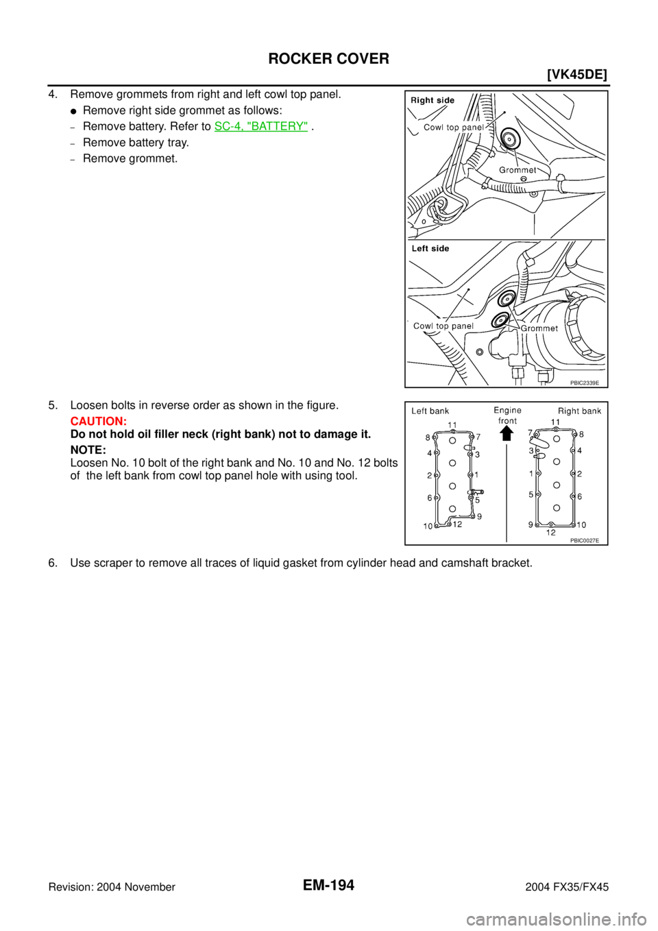
4. Remove grommets from right and left cowl top panel.
�Remove right side grommet as follows:
–Remove battery. Refer to SC-4, "BATTERY" .
–Remove battery tray.
–Remove grommet.
5. Loosen bolts in reverse order as shown in the figure.
CAUTION:
Do not hold oil filler neck (right bank) not to damage it.
NOTE:
Loosen No. 10 bolt of the right bank and No. 10 and No. 12 bolts
of the left bank from cowl top panel hole with using tool.
6. Use scraper to remove all traces of liquid gasket from cylinder head and camshaft bracket.
PBIC2339E
PBIC0027E
Page 2920 of 4449
![INFINITI FX35 2004 Service Manual ROCKER COVER
EM-195
[VK45DE]
C
D
E
F
G
H
I
J
K
L
MA
EM
Revision: 2004 November 2004 FX35/FX45
INSTALLATION
1. Apply liquid gasket to joint part of cylinder head and camshaft
bracket as follows:
NOTE:](/manual-img/42/57021/w960_57021-2919.png "INFINITI FX35 2004 Service Manual ROCKER COVER
EM-195
[VK45DE]
C
D
E
F
G
H
I
J
K
L
MA
EM
Revision: 2004 November 2004 FX35/FX45
INSTALLATION
1. Apply liquid gasket to joint part of cylinder head and camshaft
bracket as follows:
NOTE:")
ROCKER COVER
EM-195
[VK45DE]
C
D
E
F
G
H
I
J
K
L
MA
EM
Revision: 2004 November 2004 FX35/FX45
INSTALLATION
1. Apply liquid gasket to joint part of cylinder head and camshaft
bracket as follows:
NOTE:
The figure shows an example of left bank side [zoomed in
shows camshaft bracket (No. 1)]. Apply only to camshaft bracket
(No. 1) for right bank side.
a. Refer to the figure “a” to apply liquid gasket to joint part of cam-
shaft bracket (both No. 1 and No. 6) and cylinder head.
b. Refer to the figure “b” to apply liquid gasket in 90 degrees to the
figure “a”.
Use Genuine RTV Silicone Sealant or equivalent. Refer to
GI-48, "
RECOMMENDED CHEMICAL PRODUCTS AND
SEALANTS" .
2. Install rocker cover.
�Check if rocker cover gasket is not dropped from installation groove of rocker cover.
3. Tighten bolts in two steps separately in numerical order as
shown in the figure.
CAUTION:
Do not hold oil filler neck (right bank) not to damage it.
NOTE:
Tighten No. 10 bolt of the right bank and No. 10 and No. 12 bolts
of the left bank from cowl top panel hole with using tool.
4. Install in the reverse order of removal after this step.
PBIC2444E
1st step : 2.0 N·m (0.2 kg-m, 18 in-lb)
2nd step : 8.3 N·m (0.85 kg-m, 73 in-lb)
PBIC0027E
Page 2923 of 4449
![INFINITI FX35 2004 Service Manual EM-198
[VK45DE]
TIMING CHAIN
Revision: 2004 November 2004 FX35/FX45
5. Remove intake valve timing control cover as follows:
a. Loosen and remove mounting bolts in the reverse order as
shown in the fi](/manual-img/42/57021/w960_57021-2922.png "INFINITI FX35 2004 Service Manual EM-198
[VK45DE]
TIMING CHAIN
Revision: 2004 November 2004 FX35/FX45
5. Remove intake valve timing control cover as follows:
a. Loosen and remove mounting bolts in the reverse order as
shown in the fi")
EM-198
[VK45DE]
TIMING CHAIN
Revision: 2004 November 2004 FX35/FX45
5. Remove intake valve timing control cover as follows:
a. Loosen and remove mounting bolts in the reverse order as
shown in the figure.
b . U s e s e a l c u t t e r [ S S T: K V 1 0 1111 0 0 ( J 3 7 2 2 8 ) ] o r e q u i v a l e n t t o o l
to cut liquid gasket for removal.
CAUTION:
�Exercise care not to damage mating surfaces.
�Pull out cover keeping levelness without an angle, as
inner part of cover is engaged with the center of camshaft
sprocket (INT).
6. Remove O-rings from front cover.
7. Obtain No. 1 cylinder at TDC of its compression stroke as follows:
a. Rotate crankshaft pulley clockwise to align the TDC identifica-
tion notch (without paint mark) with timing indicator on front
cover.
b. Make sure that both intake and exhaust cam noses of No. 1 cyl-
inder (engine front side of left bank) are located as shown in the
figure.
�If not, turn crankshaft pulley one revolution (360 degrees) and
align as shown in the figure.
8. Remove crankshaft pulley as follows:
PBIC0051E
SBIA0374E
PBIC2341E
KBIA0400J
![INFINITI FX35 2004 Service Manual PREPARATION
EM-163
[VK45DE]
C
D
E
F
G
H
I
J
K
L
MA
EM
Revision: 2004 November 2004 FX35/FX45KV10114700
(J38139)
Main bearing cap removerRemoving crankshaft main bearing cap
KV10107902
(J38959)
Valve o](/manual-img/42/57021/w960_57021-2887.png "INFINITI FX35 2004 Service Manual PREPARATION
EM-163
[VK45DE]
C
D
E
F
G
H
I
J
K
L
MA
EM
Revision: 2004 November 2004 FX35/FX45KV10114700
(J38139)
Main bearing cap removerRemoving crankshaft main bearing cap
KV10107902
(J38959)
Valve o")
![INFINITI FX35 2004 Service Manual EM-164
[VK45DE]
PREPARATION
Revision: 2004 November 2004 FX35/FX45
Commercial Service ToolsABS006I3
—
(J-45476)
Ring gear stopperRemoving and installing crankshaft pulley
—
(J-45488)
Quick connect](/manual-img/42/57021/w960_57021-2888.png "INFINITI FX35 2004 Service Manual EM-164
[VK45DE]
PREPARATION
Revision: 2004 November 2004 FX35/FX45
Commercial Service ToolsABS006I3
—
(J-45476)
Ring gear stopperRemoving and installing crankshaft pulley
—
(J-45488)
Quick connect")