Page 2955 of 4449
![INFINITI FX35 2004 Service Manual EM-230
[VK45DE]
CYLINDER HEAD
Revision: 2004 November 2004 FX35/FX45
7. Install valve collet.
�Compress valve spring with valve spring compressor, attach-
ment and adapter (SST). Install valve collet](/manual-img/42/57021/w960_57021-2954.png "INFINITI FX35 2004 Service Manual EM-230
[VK45DE]
CYLINDER HEAD
Revision: 2004 November 2004 FX35/FX45
7. Install valve collet.
�Compress valve spring with valve spring compressor, attach-
ment and adapter (SST). Install valve collet")
EM-230
[VK45DE]
CYLINDER HEAD
Revision: 2004 November 2004 FX35/FX45
7. Install valve collet.
�Compress valve spring with valve spring compressor, attach-
ment and adapter (SST). Install valve collet with magnetic
hand.
CAUTION:
When working, take care not to damage valve lifter holes.
�Tap stem edge lightly with plastic hammer after installation to
check its installed condition.
8. Install valve lifter and adjusting shim.
�Install in the original position.
9. Install spark plug tube.
�Press-fit spark plug tube following procedure below.
a. Remove old liquid gasket adhering to cylinder-head mounting
hole.
b. Apply liquid gasket to area within approximately 12 mm (0.47 in)
from edge of spark plug tube press-fit side.
Use Genuine RTV Silicone Sealant or equivalent . Refer to
GI-48, "
RECOMMENDED CHEMICAL PRODUCTS AND
SEALANTS" .
c. Using drift, press-fit spark plug tube so that its height “H” is as
specified in the figure.
CAUTION:
�When press-fitting, take care not to deform spark plug tube.
�After press-fitting, wipe off liquid gasket protruding onto cylinder-head upper face.
10. Install spark plug with spark plug wrench (commercial service tool).
Inspection After DisassemblyABS006IS
VALVE DIMENSIONS
�Check dimensions of each valve. For dimensions, refer to .
�If dimensions are out of the standard, replace valve.EM-270,
"Valve Dimensions" .
PBIC2360E
Standard press-fit height “H” :
: 38.4 - 39.4 mm (1.512 - 1.551 in)
KBIA1248E
SEM188A
Page 2956 of 4449
![INFINITI FX35 2004 Service Manual CYLINDER HEAD
EM-231
[VK45DE]
C
D
E
F
G
H
I
J
K
L
MA
EM
Revision: 2004 November 2004 FX35/FX45
VALVE GUIDE CLEARANCE
Valve Stem Diameter
Measure diameter of valve stem with micrometer.
Valve Guide Inn](/manual-img/42/57021/w960_57021-2955.png "INFINITI FX35 2004 Service Manual CYLINDER HEAD
EM-231
[VK45DE]
C
D
E
F
G
H
I
J
K
L
MA
EM
Revision: 2004 November 2004 FX35/FX45
VALVE GUIDE CLEARANCE
Valve Stem Diameter
Measure diameter of valve stem with micrometer.
Valve Guide Inn")
CYLINDER HEAD
EM-231
[VK45DE]
C
D
E
F
G
H
I
J
K
L
MA
EM
Revision: 2004 November 2004 FX35/FX45
VALVE GUIDE CLEARANCE
Valve Stem Diameter
Measure diameter of valve stem with micrometer.
Valve Guide Inner Diameter
Measure inner diameter of valve guide with inside micrometer.
Valve Guide Clearance
(Valve guide clearance) = (Valve guide inner diameter) – (Valve stem diameter).
�If it exceeds the limit, replace valve and/or valve guide.
VALVE GUIDE REPLACEMENT
When valve guide is removed, replace with oversized [0.2 mm (0.008 in)] valve guide.
1. To remove valve guide, heat cylinder head to 110 to 130°C (230
to 266°F) by soaking in heated oil.
2. Drive out valve guide with a press [under a 20 kN (2 ton, 2.2 US
ton, 2.0 lmp ton) pressure] or hammer and suitable tool.
CAUTION:
Cylinder head contains heat. When working, wear protec-
tive equipment to avoid getting burned.Standard
Intake : 5.972 - 5.980 mm (0.2351 - 0.2354 in)
Exhaust : 5.962 - 5.970 mm (0.2347 - 0.2350 in)
SEM938C
Standard
Intake and Exhaust : 6.000 - 6.018 mm (0.2362 - 0.2369 in)
Valve guide clearance:
Standard
Intake : 0.020 - 0.046 mm (0.0008 - 0.0018 in)
Exhaust : 0.030 - 0.056 mm (0.0012 - 0.0022 in)
Limit
Intake : 0.08 mm (0.003 in)
Exhaust : 0.1 mm (0.004 in)
SEM008A
SEM931C
Page 2957 of 4449
![INFINITI FX35 2004 Service Manual EM-232
[VK45DE]
CYLINDER HEAD
Revision: 2004 November 2004 FX35/FX45
3. Using valve guide reamer (commercial service tool), ream cylin-
der head valve guide hole.
4. Heat cylinder head to 110 to 130°](/manual-img/42/57021/w960_57021-2956.png "INFINITI FX35 2004 Service Manual EM-232
[VK45DE]
CYLINDER HEAD
Revision: 2004 November 2004 FX35/FX45
3. Using valve guide reamer (commercial service tool), ream cylin-
der head valve guide hole.
4. Heat cylinder head to 110 to 130°")
EM-232
[VK45DE]
CYLINDER HEAD
Revision: 2004 November 2004 FX35/FX45
3. Using valve guide reamer (commercial service tool), ream cylin-
der head valve guide hole.
4. Heat cylinder head to 110 to 130°C (230 to 266°F) by soaking in
heated oil.
5. Press valve guide from camshaft side to dimensions as in the
figure.
CAUTION:
Cylinder head contains heat. When working, wear protec-
tive equipment to avoid getting burned.
6. Using valve guide reamer (commercial service tool), apply
reamer finish to valve guide.
VALVE SEAT CONTACT
�After confirming that the dimensions of valve guides and valves
are within specifications, perform this procedure.
�Apply prussian blue (or white lead) onto contacting surface of
valve seat to check the condition of the valve contact on the sur-
face.
�Check if the contact area band is continuous all around the cir-
cumference.
�If not, grind to adjust valve fitting and check again. If the contact-
ing surface still has NG conditions even after the re-check,
replace valve seat.Valve guide hole diameter (for service parts):
Intake and exhaust
: 10.175 - 10.196 mm (0.4006 - 0.4014 in)
SEM932C
SEM008A
PBIC0078E
Standard:
Intake and exhaust
: 6.000 - 6.018 mm (0.2362 - 0.2369 in)
SEM932C
SBIA0322E
Page 2958 of 4449
![INFINITI FX35 2004 Service Manual CYLINDER HEAD
EM-233
[VK45DE]
C
D
E
F
G
H
I
J
K
L
MA
EM
Revision: 2004 November 2004 FX35/FX45
VALVE SEAT REPLACEMENT
When valve seat is removed, replace with oversized [0.5 mm (0.020 in)] valve seat.](/manual-img/42/57021/w960_57021-2957.png "INFINITI FX35 2004 Service Manual CYLINDER HEAD
EM-233
[VK45DE]
C
D
E
F
G
H
I
J
K
L
MA
EM
Revision: 2004 November 2004 FX35/FX45
VALVE SEAT REPLACEMENT
When valve seat is removed, replace with oversized [0.5 mm (0.020 in)] valve seat.")
CYLINDER HEAD
EM-233
[VK45DE]
C
D
E
F
G
H
I
J
K
L
MA
EM
Revision: 2004 November 2004 FX35/FX45
VALVE SEAT REPLACEMENT
When valve seat is removed, replace with oversized [0.5 mm (0.020 in)] valve seat.
1. Bore out old seat until it collapses. Boring should not continue beyond the bottom face of the seat recess
in cylinder head. Set the machine depth stop to ensure this.
CAUTION:
Prevent to scratch cylinder head by excessive boring.
2. Ream cylinder head recess diameter for service valve seat.
�Be sure to ream in circles concentric to valve guide center.
This will enable valve to fit correctly.
3. Heat cylinder head to 110 to 130°C (230 to 266°F) by soaking in
heated oil.
4. Provide valve seats cooled well with dry ice. Force fit valve seat into cylinder head.
CAUTION:
�Avoid directly touching cold valve seats.
�Cylinder head contains heat. When working, wear protective equipment to avoid getting burned.
5. Using valve seat cutter set (commercial service tool) or valve
seat grinder, finish seat to the specified dimensions.
CAUTION:
When using valve seat cutter, firmly grip cutter handle with
both hands. Then, press on the contacting surface all
around the circumference to cut in a single drive. Improper
pressure on with cutter or cutting many different times may
result in stage valve seat. Oversize [0.5 mm (0.020 in)]
Intake : 37.500 - 37.516 mm (1.4764 - 1.4770 in)
Exhaust : 32.700 - 32.716 mm (1.2874 - 1.2880 in)
SEM795A
SEM008A
SEM934C
Page 2959 of 4449
EM-234
[VK45DE]
CYLINDER HEAD
Revision: 2004 November 2004 FX35/FX45
Grind to obtain the dimensions indicated in the figure.
6. Using compound, grind to adjust valve fitting.
7. Check again for normal contact. Refer to EM-232, "
VALVE SEAT CONTACT" .
VALVE SPRING SQUARENESS
�Set try square along the side of valve spring and rotate spring.
Measure the maximum clearance between the top face of spring
and try square.
�If it exceeds the limit, replace valve spring.
PBIC2363E
Limit : 2.0 mm (0.079 in)
PBIC0080E
Page 2960 of 4449
CYLINDER HEAD
EM-235
[VK45DE]
C
D
E
F
G
H
I
J
K
L
MA
EM
Revision: 2004 November 2004 FX35/FX45
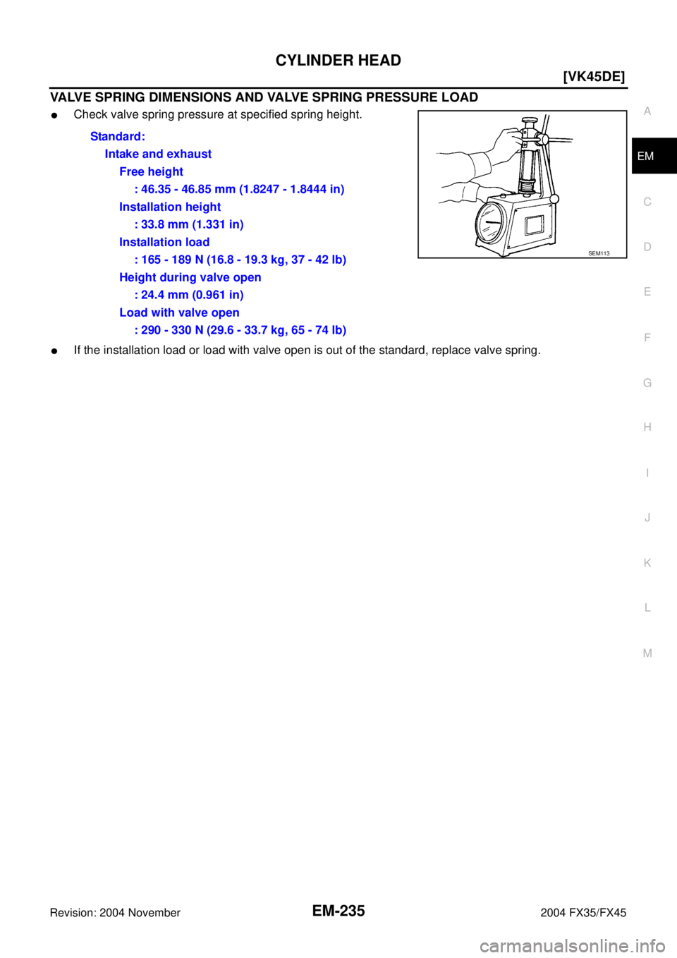
VALVE SPRING DIMENSIONS AND VALVE SPRING PRESSURE LOAD
�Check valve spring pressure at specified spring height.
�If the installation load or load with valve open is out of the standard, replace valve spring.Standard:
Intake and exhaust
Free height
: 46.35 - 46.85 mm (1.8247 - 1.8444 in)
Installation height
: 33.8 mm (1.331 in)
Installation load
: 165 - 189 N (16.8 - 19.3 kg, 37 - 42 lb)
Height during valve open
: 24.4 mm (0.961 in)
Load with valve open
: 290 - 330 N (29.6 - 33.7 kg, 65 - 74 lb)
SEM113
Page 2963 of 4449
![INFINITI FX35 2004 Service Manual EM-238
[VK45DE]
ENGINE ASSEMBLY
Revision: 2004 November 2004 FX35/FX45
�After disconnection, plug the opening on transmission side.
11. Remove front drive shaft (both side). Refer to FAX-12, "
FRONT D](/manual-img/42/57021/w960_57021-2962.png "INFINITI FX35 2004 Service Manual EM-238
[VK45DE]
ENGINE ASSEMBLY
Revision: 2004 November 2004 FX35/FX45
�After disconnection, plug the opening on transmission side.
11. Remove front drive shaft (both side). Refer to FAX-12, \"
FRONT D")
EM-238
[VK45DE]
ENGINE ASSEMBLY
Revision: 2004 November 2004 FX35/FX45
�After disconnection, plug the opening on transmission side.
11. Remove front drive shaft (both side). Refer to FAX-12, "
FRONT DRIVE SHAFT" .
12. Remove front propeller shaft. Refer to PR-4, "
FRONT PROPELLER SHAFT" .
13. Remove three way catalyst (both bank). Refer to EM-178, "
EXHAUST MANIFOLD AND THREE WAY
CATALYST" .
Removal Work
1. Install engine slingers into front of left bank cylinder head and
front of right bank cylinder head.
2. Lift with hoist and secure engine in position.
3. Use manual lift table caddy (commercial service tool) or equivalently rigid tool such as transmission jack.
Securely support bottom of suspension member and transmission.
CAUTION:
Put a piece of wood or something similar as the supporting surface, secure a completely stable
condition.
4. Remove front suspension member mounting nuts with power tool. Refer to FSU-6, "
FRONT SUSPEN-
SION ASSEMBLY" .
5. Carefully lower jack, or raise lift to remove engine, transmission
front final drive and front suspension member assembly. When
performing work, observe the following caution:
CAUTION:
�Confirm there is no interference with vehicle.
�Make sure that all connection points have been discon-
nected.
�Keep in mind the center of vehicle gravity changes. If
necessary, use jack(s) to support vehicle at rear jacking
point(s) to prevent it from falling it off the lift.
Separation Work
1. Change engine slinger installing to cylinder head (right bank).
NOTE:
In order to keep secure position when hoisting engine.
2. Remove engine mounting insulators (RH and LH) under side nut with power tool.
3. Lift with hoist and separate engine and transmission assembly from front suspension member.
CAUTION:
�Before and during this lifting, always check if any harnesses are left connected.
�Avoid damage to and oil/grease smearing or spills onto engine mounting insulator.
4. Remove alternator. Refer to SC-23, "
CHARGING SYSTEM" . Slinger bolts:
:33.4 N·m (3.4 kg-m, 25 ft-lb)
PBIC1556E
PBIC1557E
Slinger bolts:
:33.4 N·m (3.4 kg-m, 25 ft-lb)
PBIC2447E
Page 2964 of 4449
![INFINITI FX35 2004 Service Manual ENGINE ASSEMBLY
EM-239
[VK45DE]
C
D
E
F
G
H
I
J
K
L
MA
EM
Revision: 2004 November 2004 FX35/FX45
5. Remove starter motor. Refer to SC-10, "STARTING SYSTEM" .
6. Separate engine from transmission assem](/manual-img/42/57021/w960_57021-2963.png "INFINITI FX35 2004 Service Manual ENGINE ASSEMBLY
EM-239
[VK45DE]
C
D
E
F
G
H
I
J
K
L
MA
EM
Revision: 2004 November 2004 FX35/FX45
5. Remove starter motor. Refer to SC-10, \"STARTING SYSTEM\" .
6. Separate engine from transmission assem")
ENGINE ASSEMBLY
EM-239
[VK45DE]
C
D
E
F
G
H
I
J
K
L
MA
EM
Revision: 2004 November 2004 FX35/FX45
5. Remove starter motor. Refer to SC-10, "STARTING SYSTEM" .
6. Separate engine from transmission assembly. Refer to AT- 2 6 9 , "
Removal and Installation (AWD models)"
.
7. Remove front final drive from engine. Refer to FFD-10, "
FRONT FINAL DRIVE ASSEMBLY" .
8. Remove engine mounting insulators (RH and LH) and brackets (RH and LH) from engine with power tool.
9. Remove engine rear member and engine mounting insulator (rear) from transmission.
INSTALLATION
Note to the following, and install in the reverse order of removal.
�Where positioning pin is used, be sure to securely insert it into the hole of mating part.
�When installing engine mount brackets (RH and LH) to cylinder
block, tighten two upper bolts (shown as “A” in the figure) first.
Then tighten two lower bolts (shown as “B” in the figure).
INSPECTION AFTER INSTALLATION
�Before starting engine, check the levels of engine coolant, engine oil and working fluid. If less than
required quantity, fill to the specified level.
�Use procedure below to check for fuel leakage.
–Turn ignition switch “ON” (with engine stopped). With fuel pressure applied to fuel piping, check for fuel
leakage at connection points.
–Start engine. With engine speed increased, check again for fuel leakage at connection points.
�Run engine to check for unusual noise and vibration.
�Warm up engine thoroughly to make sure there is no leakage of engine coolant, engine oil, working fluid,
fuel and exhaust gas.
�Bleed air from passages in pipes and tubes of applicable lines, such as in cooling system.
�After cooling down engine, again check amounts of engine coolant, engine oil and working fluid. Refill to
specified level, if necessary.
Summary of the inspection items:
PBIC2365E
Item Before starting engine Engine running After engine stopped
Engine coolant Level Leakage Level
Engine oil Level Leakage Level
Working fluid Level Leakage Level
Fuel — Leakage —
Exhaust gas — Leakage —
![INFINITI FX35 2004 Service Manual EM-234
[VK45DE]
CYLINDER HEAD
Revision: 2004 November 2004 FX35/FX45
Grind to obtain the dimensions indicated in the figure.
6. Using compound, grind to adjust valve fitting.
7. Check again for norma](/manual-img/42/57021/w960_57021-2958.png "INFINITI FX35 2004 Service Manual EM-234
[VK45DE]
CYLINDER HEAD
Revision: 2004 November 2004 FX35/FX45
Grind to obtain the dimensions indicated in the figure.
6. Using compound, grind to adjust valve fitting.
7. Check again for norma")