Page 2790 of 4449
TIMING CHAIN
EM-65
[VQ35DE]
C
D
E
F
G
H
I
J
K
L
MA
EM
Revision: 2004 November 2004 FX35/FX45
18. Remove collared O-ring from front timing chain case (left and
right side).
19. Remove right and left rocker covers. Refer to EM-51, "
ROCKER COVER" .
20. Obtain compression TDC of No. 1 cylinder as follows:
a. Rotate crankshaft pulley clockwise to align timing mark (grooved
line without color) with timing indicator.
b. Make sure intake and exhaust cam noses on No. 1 cylinder
(engine front side of right bank) are located as shown in the fig-
ure.
�If not, turn crankshaft one revolution (360°) and align as
shown.
21. Remove crankshaft pulley with the following procedure:
a. Remove rear cover plate (2WD) or starter motor (AWD) and set
ring gear stopper (SST) as shown in the figure. Refer to SC-10,
"STARTING SYSTEM" .
PBIC2045E
KBIA1717J
SEM418G
PBIC1098E
Page 2795 of 4449
EM-70
[VQ35DE]
TIMING CHAIN
Revision: 2004 November 2004 FX35/FX45
32. Remove O-rings from cylinder head.
33. Remove O-rings from cylinder block.
34. Remove timing chain tensioners (secondary) from cylinder head as the following, if necessary.
a. Remove No. 1 camshaft brackets. Refer to EM-83, "
REMOVAL" .
b. Remove timing chain tensioners (secondary) with stopper pin attached.
35. Use a scraper to remove all traces of liquid gasket from front
and rear timing chain cases, and opposite mating surfaces.
CAUTION:
Be careful not to allow gasket fragments to enter oil pan.
�Remove old liquid gasket from the bolt hole and thread.
SBIA0496E
PBIC0788E
SEM737G
PBIC2084E
Page 2797 of 4449
EM-72
[VQ35DE]
TIMING CHAIN
Revision: 2004 November 2004 FX35/FX45
1. Install timing chain tensioners (secondary) to cylinder head as the following if removed. Refer to EM-87,
"INSTALLATION" .
a. Install chain tensioners with stopper pin attached and new O-rings.
b. Install No. 1 camshaft brackets. Refer to EM-87, "
INSTALLATION" .
2. Install new O-rings onto cylinder block.
3. Install new O-rings to cylinder head.
4. Apply liquid gasket to rear timing chain case back side as shown with tube presser [SST: WS39930000 ( –
)].
Use Genuine RTV Silicone Sealant or equivalent. Refer to GI-48, "
RECOMMENDED CHEMICAL
PRODUCTS AND SEALANTS".
CAUTION:
�For “A” in the figure, completely wipe out liquid gasket extended on a portion touching at
engine coolant.
PBIC0788E
SBIA0496E
Page 2798 of 4449
TIMING CHAIN
EM-73
[VQ35DE]
C
D
E
F
G
H
I
J
K
L
MA
EM
Revision: 2004 November 2004 FX35/FX45
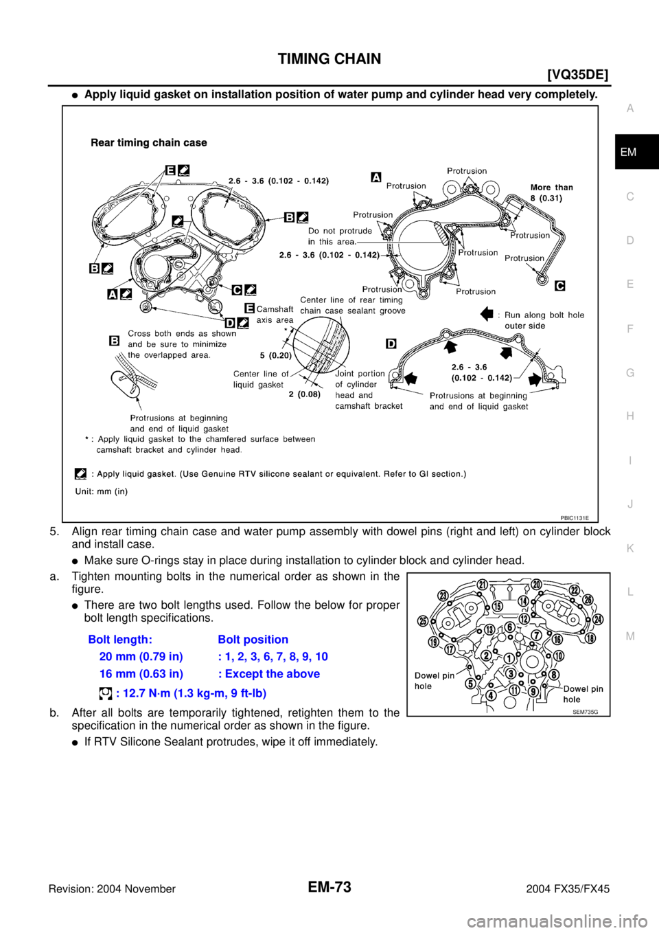
�Apply liquid gasket on installation position of water pump and cylinder head very completely.
5. Align rear timing chain case and water pump assembly with dowel pins (right and left) on cylinder block
and install case.
�Make sure O-rings stay in place during installation to cylinder block and cylinder head.
a. Tighten mounting bolts in the numerical order as shown in the
figure.
�There are two bolt lengths used. Follow the below for proper
bolt length specifications.
b. After all bolts are temporarily tightened, retighten them to the
specification in the numerical order as shown in the figure.
�If RTV Silicone Sealant protrudes, wipe it off immediately.Bolt length: Bolt position
20 mm (0.79 in) : 1, 2, 3, 6, 7, 8, 9, 10
16 mm (0.63 in) : Except the above
: 12.7 N·m (1.3 kg-m, 9 ft-lb)
PBIC1131E
SEM735G
Page 2799 of 4449
![INFINITI FX35 2004 Service Manual EM-74
[VQ35DE]
TIMING CHAIN
Revision: 2004 November 2004 FX35/FX45
6. After installing rear timing chain case, check surface height dif-
ference between following parts on oil pan mounting surface.
�I](/manual-img/42/57021/w960_57021-2798.png "INFINITI FX35 2004 Service Manual EM-74
[VQ35DE]
TIMING CHAIN
Revision: 2004 November 2004 FX35/FX45
6. After installing rear timing chain case, check surface height dif-
ference between following parts on oil pan mounting surface.
�I")
EM-74
[VQ35DE]
TIMING CHAIN
Revision: 2004 November 2004 FX35/FX45
6. After installing rear timing chain case, check surface height dif-
ference between following parts on oil pan mounting surface.
�If not within standard, repeat above installation procedure.
7. Position crankshaft so No. 1 piston is set at TDC on the com-
pression stroke.
�Make sure that dowel pin hole, dowel pin and crankshaft key
are located as shown in the figure.
NOTE:
Though camshaft does not stop at position as shown in the
figure, for the placement of cam nose, it is generally accepted
camshaft is placed for the same direction of the figure.
CAUTION:
Hole on small dia. side must be used for intake side dowel pin hole. Do not misidentify (ignore
big dia. side).
8. Install timing chains (secondary) and camshaft sprockets.
CAUTION:
Matching marks between timing chain and sprockets slip
easily. Confirm all matching mark positions repeatedly dur-
ing the installation process.
a. Push plunger of secondary chain tensioner and keep it pressed
in with a stopper pin.Standard (Rear timing chain case to cylinder block):
–0.24 to 0.14 mm (–0.0094 to 0.0055 in)
SEM943G
Camshaft dowel pin hole (intake side)
: At cylinder head upper face side in each bank.
Camshaft dowel pin (exhaust side)
: At cylinder head upper face side in each bank.
Crankshaft key
: At cylinder head side of right bank.
KBIA1073E
SEM430G
Page 2807 of 4449
EM-82
[VQ35DE]
CAMSHAFT
Revision: 2004 November 2004 FX35/FX45
CAMSHAFTPFP:13001
Removal and InstallationABS00FPH
1.Intake valve timing control solenoid
valve2. Gasket 3. Camshaft bracket (No. 2 to No. 4)
4. Camshaft (EXH) 5. Camshaft (INT) 6. Camshaft bracket (No. 1)
7. Dowel pin 8. Valve lifter 9. O-ring
10. Chain tensioner 11. Spring 12. Plunger
13. Cylinder head (right bank) 14. Cylinder head (left bank) 15.Camshaft position sensor (PHASE)
(right bank)
16.Camshaft position sensor (PHASE)
(left bank)
SBIA0576E
Page 2808 of 4449
![INFINITI FX35 2004 Service Manual CAMSHAFT
EM-83
[VQ35DE]
C
D
E
F
G
H
I
J
K
L
MA
EM
Revision: 2004 November 2004 FX35/FX45
REMOVAL
1. Remove front timing chain case, camshaft sprocket, timing chain and rear timing chain case. Refer to](/manual-img/42/57021/w960_57021-2807.png "INFINITI FX35 2004 Service Manual CAMSHAFT
EM-83
[VQ35DE]
C
D
E
F
G
H
I
J
K
L
MA
EM
Revision: 2004 November 2004 FX35/FX45
REMOVAL
1. Remove front timing chain case, camshaft sprocket, timing chain and rear timing chain case. Refer to")
CAMSHAFT
EM-83
[VQ35DE]
C
D
E
F
G
H
I
J
K
L
MA
EM
Revision: 2004 November 2004 FX35/FX45
REMOVAL
1. Remove front timing chain case, camshaft sprocket, timing chain and rear timing chain case. Refer to EM-
63, "TIMING CHAIN" .
2. If necessary, remove camshaft position sensor (PHASE) (right
and left banks) from cylinder head back side.
CAUTION:
�Handle carefully to avoid dropping and shocks.
�Do not disassemble.
�Do not allow metal powder to adhere to magnetic part at
sensor tip.
�Do not place sensors in a location where they are
exposed to magnetism.
3. Remove intake valve timing control solenoid valve from No.1
camshaft bracket.
4. Remove intake and exhaust camshaft brackets.
�Mark camshafts, camshaft brackets, and bolts so they are
placed in the same position and direction for installation.
�Equally loosen camshaft bracket bolts in several steps in the
reverse order as shown in the figure.
5. Remove camshaft.
6. Remove valve lifter.
�Identify installation positions, and store them without mixing them up.
KBIA1046E
SEM443GA
PBIC2050E
Page 2809 of 4449
![INFINITI FX35 2004 Service Manual EM-84
[VQ35DE]
CAMSHAFT
Revision: 2004 November 2004 FX35/FX45
7. Remove secondary timing chain tensioner from cylinder head.
�Remove chain tensioner with its stopper pin attached.
NOTE:
Stopper pin w](/manual-img/42/57021/w960_57021-2808.png "INFINITI FX35 2004 Service Manual EM-84
[VQ35DE]
CAMSHAFT
Revision: 2004 November 2004 FX35/FX45
7. Remove secondary timing chain tensioner from cylinder head.
�Remove chain tensioner with its stopper pin attached.
NOTE:
Stopper pin w")
EM-84
[VQ35DE]
CAMSHAFT
Revision: 2004 November 2004 FX35/FX45
7. Remove secondary timing chain tensioner from cylinder head.
�Remove chain tensioner with its stopper pin attached.
NOTE:
Stopper pin was attached when secondary timing chain was
removed.
INSPECTION AFTER REMOVAL
Camshaft Runout
1. Put V block on precise flat bed, and support No. 2 and No. 4
journal of camshaft.
CAUTION:
Do not support journal No. 1 (on the side of camshaft
sprocket) because it has a different diameter from the other
three locations.
2. Set dial gauge vertically to No. 3 journal.
3. Turn camshaft to one direction with hands, and measure cam-
shaft runout on dial gauge. (Total indicator reading)
4. If it exceeds the standard, replace camshaft.
Camshaft Cam Height
1. Measure camshaft cam height.
2. If wear is beyond the limit, replace camshaft.
Camshaft Journal Oil Clearance
Outer Diameter of Camshaft Journal
Measure outer diameter of camshaft journal.
Inner Diameter of Camshaft Bracket
�Tighten camshaft bracket bolt with specified torque. Refer to EM-87, "INSTALLATION" .
SBIA0499E
Standard : Less than 0.05 mm (0.0020 in)PBIC0929E
Standard cam height (intake and exhaust)
: 44.865 - 45.055 mm (1.7663 - 1.7738 in)
Cam wear limit
: 0.2 mm (0.008 in)
EMQ0072D
Standard outer diameter:
No. 1: 25.935 - 25.955 mm (1.0211 - 1.0218 in)
No. 2, 3, 4: 23.445 - 23.465 mm (0.9230 - 0.9238 in)
PBIC0040E
![INFINITI FX35 2004 Service Manual TIMING CHAIN
EM-65
[VQ35DE]
C
D
E
F
G
H
I
J
K
L
MA
EM
Revision: 2004 November 2004 FX35/FX45
18. Remove collared O-ring from front timing chain case (left and
right side).
19. Remove right and left ro](/manual-img/42/57021/w960_57021-2789.png "INFINITI FX35 2004 Service Manual TIMING CHAIN
EM-65
[VQ35DE]
C
D
E
F
G
H
I
J
K
L
MA
EM
Revision: 2004 November 2004 FX35/FX45
18. Remove collared O-ring from front timing chain case (left and
right side).
19. Remove right and left ro")
![INFINITI FX35 2004 Service Manual EM-70
[VQ35DE]
TIMING CHAIN
Revision: 2004 November 2004 FX35/FX45
32. Remove O-rings from cylinder head.
33. Remove O-rings from cylinder block.
34. Remove timing chain tensioners (secondary) from cy](/manual-img/42/57021/w960_57021-2794.png "INFINITI FX35 2004 Service Manual EM-70
[VQ35DE]
TIMING CHAIN
Revision: 2004 November 2004 FX35/FX45
32. Remove O-rings from cylinder head.
33. Remove O-rings from cylinder block.
34. Remove timing chain tensioners (secondary) from cy")
![INFINITI FX35 2004 Service Manual EM-72
[VQ35DE]
TIMING CHAIN
Revision: 2004 November 2004 FX35/FX45
1. Install timing chain tensioners (secondary) to cylinder head as the following if removed. Refer to EM-87,
"INSTALLATION" .
a. Inst](/manual-img/42/57021/w960_57021-2796.png "INFINITI FX35 2004 Service Manual EM-72
[VQ35DE]
TIMING CHAIN
Revision: 2004 November 2004 FX35/FX45
1. Install timing chain tensioners (secondary) to cylinder head as the following if removed. Refer to EM-87,
\"INSTALLATION\" .
a. Inst")
![INFINITI FX35 2004 Service Manual EM-82
[VQ35DE]
CAMSHAFT
Revision: 2004 November 2004 FX35/FX45
CAMSHAFTPFP:13001
Removal and InstallationABS00FPH
1.Intake valve timing control solenoid
valve2. Gasket 3. Camshaft bracket (No. 2 to N](/manual-img/42/57021/w960_57021-2806.png "INFINITI FX35 2004 Service Manual EM-82
[VQ35DE]
CAMSHAFT
Revision: 2004 November 2004 FX35/FX45
CAMSHAFTPFP:13001
Removal and InstallationABS00FPH
1.Intake valve timing control solenoid
valve2. Gasket 3. Camshaft bracket (No. 2 to N")