Page 4267 of 4449
SRS-26
TROUBLE DIAGNOSIS
Revision: 2004 November 2004 FX35/FX45
6. Touch “SELF-DIAG [PAST]”.
7. If diagnostic codes are displayed on “SELF-DIAG [PAST]”, go to
step 10.
If no malfunction is detected on “SELF-DIAG [PAST]”, touch
“BACK” and go back to “SELECT DIAG MODE”.
8. Touch “TROUBLE DIAG RECORD”.
NOTE:
With “TROUBLE DIAG RECORD”, diagnosis results previously
erased by a reset operation can be displayed.
9. Diagnostic code is displayed on “TROUBLE DIAG RECORD”.
10. Touch “PRINT”.
11. Compare diagnostic codes to SRS-25, "
DIAGNOSTIC PROCE-
DURE 5" .
12. Touch “BACK” key of CONSULT-II until “SELECT SYSTEM”
appears.
13. Turn ignition switch OFF, then turn off and disconnect CON-
SULT-II, and both battery cables.
14. Repair the system as outlined by the “Repair order” in “Intermit-
tent Malfunction Diagnostic Code Chart”, that corresponds to the
SRS697
SRS700
SRS702
SRS697
SHIA0182E
Page 4270 of 4449

TROUBLE DIAGNOSIS
SRS-29
C
D
E
F
G
I
J
K
L
MA
B
SRS
Revision: 2004 November 2004 FX35/FX45
Trouble Diagnosis without CONSULT-IIAHS000HT
DIAGNOSTIC PROCEDURE 6
Inspecting SRS Malfunctioning Parts by Using “AIR BAG” Warning Lamp — Diagnosis Mode
NOTE:
SRS will not enter Diagnosis mode if no malfunction is detected in User mode.
1. Turn ignition switch ON.
2. After “AIR BAG” warning lamp lights for 7 seconds, turn ignition switch OFF within 1 second.
3. Wait more than 3 seconds.
4. Repeat the steps 1 to 3 twice. (Perform three times in all.)
5. Turn ignition switch ON.
SRS is now in Diagnosis mode.
“AIR BAG” warning lamp operates in Diagnosis mode as follows:
CURTAIN MODULE RH
[OPEN]�RH side curtain air bag module circuit is open. 1. Visually check the wiring harness
connection.
2. Replace the harness if it has visible
damage.
3. If the harness check result is OK,
replace the diagnosis sensor unit
and RH side curtain air bag module.
(Before disposal, it must be
deployed.) CURTAIN MODULE RH
[VB-SHORT]
�RH side curtain air bag module circuit is shorted to a power sup-
ply circuit.
CURTAIN MODULE RH
[GND-SHORT]
�RH side curtain air bag module circuit is shorted to ground.
CURTAIN MODULE RH
[SHORT]
�RH side curtain air bag module circuit is shorted between lines.
CONTROL UNIT
�Diagnosis sensor unit is malfunctioning. 1. Visually check the wiring harness
connection.
2. Replace the diagnosis sensor unit. Diagnostic item ExplanationRepair order
“Recheck SRS at each replacement”
Page 4275 of 4449

SRS-34
TROUBLE DIAGNOSIS
Revision: 2004 November 2004 FX35/FX45
Trouble Diagnosis: “AIR BAG” Warning Lamp Does Not Turn OFFAHS000HU
DIAGNOSTIC PROCEDURE 7
1. CHECK THE DEPLOYMENT OF AIR BAG MODULE
Is air bag module deployed?
YES or NO
YES >> Refer to SRS-56, "COLLISION DIAGNOSIS" .
NO >> GO TO 2.
2. CHECK THE AIR BAG FUSE
Check 10A fuse [No. 13, located in fuse block (J/B)].
Refer to PG-3, "
POWER SUPPLY ROUTING CIRCUIT" .
OK or NG
OK >> GO TO 4.
NG >> GO TO 3.
3. CHECK AIR BAG FUSE AGAIN
Replace “AIR BAG” fuse and turn ignition switch ON.
Does the
“AIR BAG” fuse blow again?
YES >> Repair main harness.
NO >>INSPECTION END
4. CHECK DIAGNOSIS SENSOR UNIT
Connect CONSULT-II and touch “START”.
�Is “AIR BAG” displayed on CONSULT-II?
YES or NO
YES >> GO TO 5.
NO >> Visually check the wiring harness connection of diagno-
sis sensor unit. If the harness connection check result is
OK, replace diagnosis sensor unit.
5. CHECK HARNESS CONNECTION
Is harness connection between warning lamp and diagnosis sensor unit OK?
OK or NG
OK >> Replace diagnosis sensor unit.
NG >> Connect “AIR BAG” warning lamp and diagnosis sensor unit connector properly. If “AIR BAG”
warning lamp still does not go off, replace harness.
SRS771
Page 4276 of 4449
TROUBLE DIAGNOSIS
SRS-35
C
D
E
F
G
I
J
K
L
MA
B
SRS
Revision: 2004 November 2004 FX35/FX45
Trouble Diagnosis: “AIR BAG” Warning Lamp Does Not Turn ONAHS000HV
DIAGNOSTIC PROCEDURE 8
1. CHECK METER FUSE
Check 10A fuse [No. 14, located in fuse block (J/B)].
Refer to PG-3, "
POWER SUPPLY ROUTING CIRCUIT" .
OK or NG
OK >> GO TO 3.
NG >> GO TO 2.
2. CHECK METER FUSE AGAIN
Replace 10A fuse [No. 14, located in fuse block (J/B)] and turn ignition switch ON.
Does the meter fuse blow again?
YES >> Repair the related harness.
NO >>INSPECTION END
3. CHECK HARNESS CONNECTION BETWEEN DIAGNOSIS SENSOR UNIT AND COMBINATION
METER
Disconnect diagnosis sensor unit connector and turn ignition switch ON.
�Does “AIR BAG” warning lamp turn ON?
YES or NO
YES >> Replace diagnosis sensor unit.
NO >> Check the ground circuit of “AIR BAG” warning lamp.
Page 4277 of 4449
SRS-36
DRIVER AIR BAG MODULE
Revision: 2004 November 2004 FX35/FX45
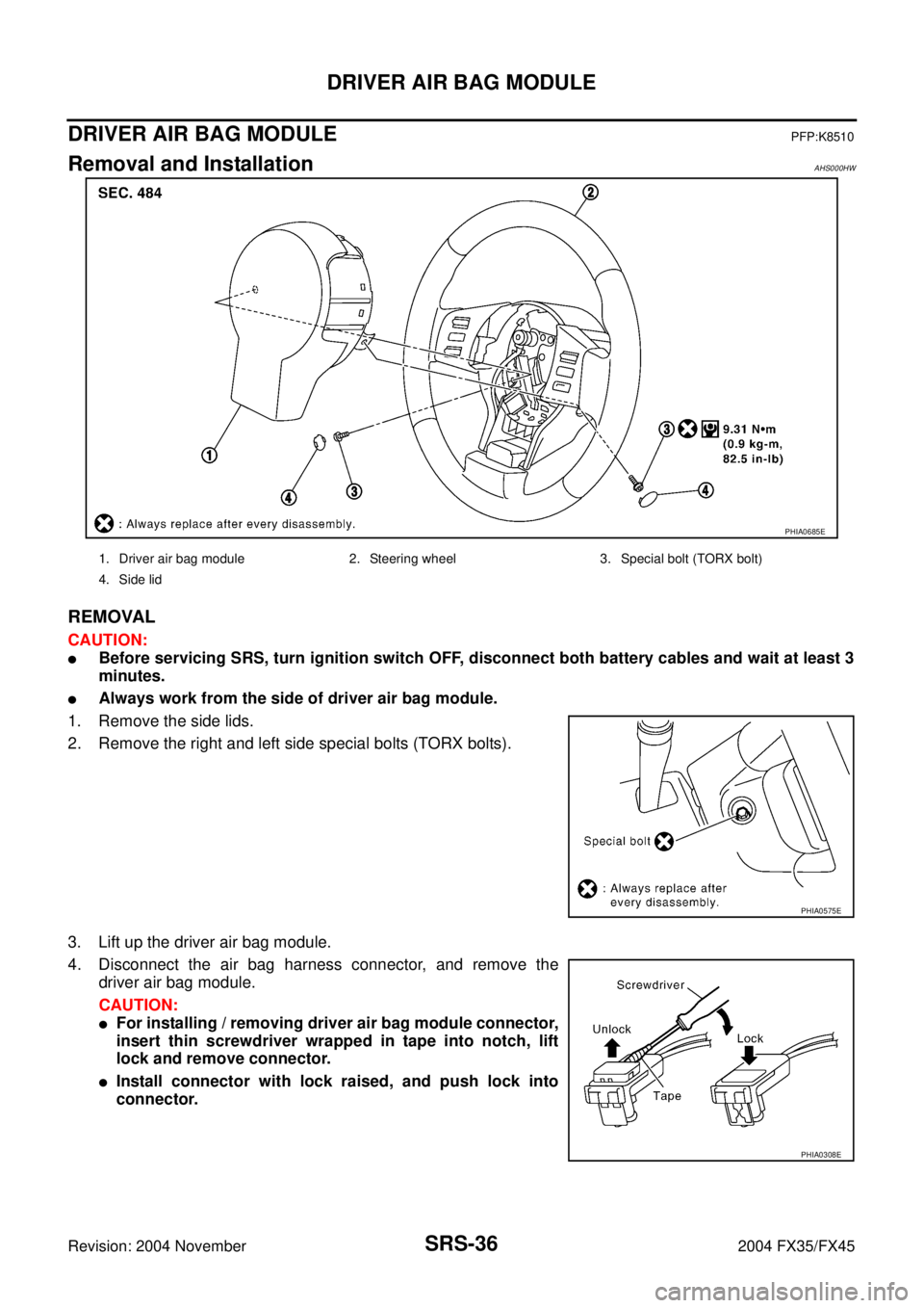
DRIVER AIR BAG MODULEPFP:K8510
Removal and InstallationAHS000HW
REMOVAL
CAUTION:
�Before servicing SRS, turn ignition switch OFF, disconnect both battery cables and wait at least 3
minutes.
�Always work from the side of driver air bag module.
1. Remove the side lids.
2. Remove the right and left side special bolts (TORX bolts).
3. Lift up the driver air bag module.
4. Disconnect the air bag harness connector, and remove the
driver air bag module.
CAUTION:
�For installing / removing driver air bag module connector,
insert thin screwdriver wrapped in tape into notch, lift
lock and remove connector.
�Install connector with lock raised, and push lock into
connector.
PHIA0685E
1. Driver air bag module 2. Steering wheel 3. Special bolt (TORX bolt)
4. Side lid
PHIA0575E
PHIA0308E
Page 4279 of 4449
SRS-38
SPIRAL CABLE
Revision: 2004 November 2004 FX35/FX45
SPIRAL CABLEPFP:25554
Removal and InstallationAHS000HX
REMOVAL
CAUTION:
Before servicing SRS, turn ignition switch OFF, disconnect both battery cables and wait at least 3 min-
utes.
1. Remove driver air bag module. Refer to SRS-36, "
Removal and Installation" .
2. Set the steering wheel in the neutral position.
3. Remove steering wheel with steering wheel puller.
CAUTION:
Be careful not to over-tighten puller on steering wheel.
4. Remove the column covers.
5. Loosen the spiral cable fixing screws, and then remove the spiral cable.
CAUTION:
�Do not disassemble spiral cable.
�Do not apply lubricant to the spiral cable.
PHIA0309E
1. Steering wheel 2. Nut 3. Spiral cable
4. Driver air bag module connector 5. Screw 6. Wiper and washer switch
7. Lighting and turn signal switch 8. Column assembly 9. Column cover
10. Screw
PHIA0100E
Page 4281 of 4449

SRS-40
FRONT PASSENGER AIR BAG MODULE
Revision: 2004 November 2004 FX35/FX45
FRONT PASSENGER AIR BAG MODULEPFP:K8515
Removal and InstallationAHS000HY
REMOVAL
CAUTION:
�Before servicing SRS, turn ignition switch OFF, disconnect both battery cables and wait at least 3
minutes.
�Always work from the side of or under front passenger air bag module.
1. Remove instrument passenger lower panel and glove box. Refer to IP-10, "
INSTRUMENT PANEL
ASSEMBLY" .
2. Remove display control unit, if navigation system is equipped.
3. Remove tire pressure warning control unit, if tire pressure warning control system is equipped.
4. Disconnect front passenger air bag module connector.
5. Remove the front passenger air bag module fixing nuts and bolt,
then remove front passenger air bag module.
CAUTION:
�Always place front passenger air bag module with caution
label side facing upward.
�Do not insert any foreign objects (screwdriver, etc.) into
front passenger air bag module.
�Do not disassemble front passenger air bag module.
�Do not use old bolts after removal; replace with new bolts.
�Replace front passenger air bag module if it has been
dropped or sustained an impact.
�Do not expose the front passenger air bag module to tem-
peratures exceeding 90°C (194°F).
�Do not allow oil, grease or water to come in contact with the
front passenger air bag module.
�After front passenger air bag module inflates, the instru-
ment panel assembly should be replaced.
INSTALLATION
Install in the reverse order of removal.
CAUTION:
�Always work from the side of or under front passenger air bag module.
�After the work is completed, perform self-diagnosis to make sure no malfunction is detected.
Refer to SRS-17, "
SRS Operation Check" .
PHIA0322E
PHIA0325E
SBF814E
Page 4282 of 4449

FRONT SIDE AIR BAG MODULE
SRS-41
C
D
E
F
G
I
J
K
L
MA
B
SRS
Revision: 2004 November 2004 FX35/FX45
FRONT SIDE AIR BAG MODULEPFP:K8EH0
Removal and InstallationAHS000HZ
REMOVAL
CAUTION:
�Removal of front side air bag module should only be done to allow deployment of front side air
bag module prior to disposal of seatback only. Only complete seatback assemblies can be
replaced. Refer to SE-101, "
Removal and Installation" .
�Before servicing SRS, turn ignition switch OFF, disconnect both battery cables and wait at least 3
minutes.
�Always work from the rear of the front side air bag module.
1. Remove front seat. Refer to SE-101, "
FRONT SEAT" .
2. Remove seatback trim and pad. Refer to SE-104, "
REMOVAL OF SEATBACK TRIM AND PAD" .
3. Remove front side air bag module harness clips.
4. Remove front side air bag module assembly fixing special nuts,
then remove front side air bag module assembly.
5. Remove front side air bag module fixing special nuts, then
remove front side air bag module from bracket.
CAUTION:
�Always place the front side air bag module standing with
the stud bolt side facing down.
�Do not insert any foreign objects (screwdrivers) into front
side air bag module.
�Do not disassemble front side air bag module.
PHIA0330E
PHIA0327E
SRS623
![INFINITI FX35 2004 Service Manual SRS-26
TROUBLE DIAGNOSIS
Revision: 2004 November 2004 FX35/FX45
6. Touch “SELF-DIAG [PAST]”.
7. If diagnostic codes are displayed on “SELF-DIAG [PAST]”, go to
step 10.
If no malfunction is det](/manual-img/42/57021/w960_57021-4266.png "INFINITI FX35 2004 Service Manual SRS-26
TROUBLE DIAGNOSIS
Revision: 2004 November 2004 FX35/FX45
6. Touch “SELF-DIAG [PAST]”.
7. If diagnostic codes are displayed on “SELF-DIAG [PAST]”, go to
step 10.
If no malfunction is det")