Page 3774 of 4449
![INFINITI FX35 2004 Service Manual PRECAUTIONS
LU-21
[VK45DE]
C
D
E
F
G
H
I
J
K
L
MA
LU
Revision: 2004 November 2004 FX35/FX45
[VK45DE]PRECAUTIONSPFP:00001
Precautions for Liquid GasketABS006IZ
LIQUID GASKET APPLICATION PROCEDURE
1. Re INFINITI FX35 2004 Service Manual PRECAUTIONS
LU-21
[VK45DE]
C
D
E
F
G
H
I
J
K
L
MA
LU
Revision: 2004 November 2004 FX35/FX45
[VK45DE]PRECAUTIONSPFP:00001
Precautions for Liquid GasketABS006IZ
LIQUID GASKET APPLICATION PROCEDURE
1. Re](/manual-img/42/57021/w960_57021-3773.png)
PRECAUTIONS
LU-21
[VK45DE]
C
D
E
F
G
H
I
J
K
L
MA
LU
Revision: 2004 November 2004 FX35/FX45
[VK45DE]PRECAUTIONSPFP:00001
Precautions for Liquid GasketABS006IZ
LIQUID GASKET APPLICATION PROCEDURE
1. Remove old liquid gasket adhering to the liquid gasket application surface and the mating surface.
�Remove liquid gasket completely from the liquid gasket application surface, mounting bolts, and bolt
holes.
2. Wipe the liquid gasket application surface and the mating surface with white gasoline (lighting and heating
use) to remove adhering moisture, grease and foreign materials.
3. Attach liquid gasket tube to tube presser [SST: WS39930000
(—)].
Use Genuine RTV Silicone Sealant or equivalent. Refer to
GI-48, "
RECOMMENDED CHEMICAL PRODUCTS AND
SEALANTS" .
�Within five minutes of liquid gasket application, install the mat-
ing component.
�If liquid gasket protrudes, wipe it off immediately.
�Do not retighten mounting bolts or nuts after the installation.
�After 30 minutes or more have passed from the installation, fill
engine oil and engine coolant.EMA0622D
Page 4279 of 4449
SRS-38
SPIRAL CABLE
Revision: 2004 November 2004 FX35/FX45
SPIRAL CABLEPFP:25554
Removal and InstallationAHS000HX
REMOVAL
CAUTION:
Before servicing SRS, turn ignition switch OFF, disconnect both battery cables and wait at least 3 min-
utes.
1. Remove driver air bag module. Refer to SRS-36, "
Removal and Installation" .
2. Set the steering wheel in the neutral position.
3. Remove steering wheel with steering wheel puller.
CAUTION:
Be careful not to over-tighten puller on steering wheel.
4. Remove the column covers.
5. Loosen the spiral cable fixing screws, and then remove the spiral cable.
CAUTION:
�Do not disassemble spiral cable.
�Do not apply lubricant to the spiral cable.
PHIA0309E
1. Steering wheel 2. Nut 3. Spiral cable
4. Driver air bag module connector 5. Screw 6. Wiper and washer switch
7. Lighting and turn signal switch 8. Column assembly 9. Column cover
10. Screw
PHIA0100E
Page 4280 of 4449
SPIRAL CABLE
SRS-39
C
D
E
F
G
I
J
K
L
MA
B
SRS
Revision: 2004 November 2004 FX35/FX45
6. Disconnect the horn switch connector, and then the spiral cable
connector.
CAUTION:
Do not tap or bump the steering wheel.
7. Remove the wiper washer switch and lighting switch from the spiral cable.
INSTALLATION
Install in the reverse order of removal.
CAUTION:
�The spiral cable may snap due to steering operation if the
cable is installed in an improper position.
�Also, with the steering linkage disconnected the cable may
snap by turning the steering wheel beyond the limited num-
ber of turns. The spiral cable can be turned counterclock-
wise about 2.5 turns from the right end position.
�After the work is completed, perform self-diagnosis to make
sure that no malfunction is detected. Refer to SRS-17, "
SRS
Operation Check" .
SHIA0193E
PHIA0101E
Page 4405 of 4449

WW-14
FRONT WIPER AND WASHER SYSTEM
Revision: 2004 November 2004 FX35/FX45
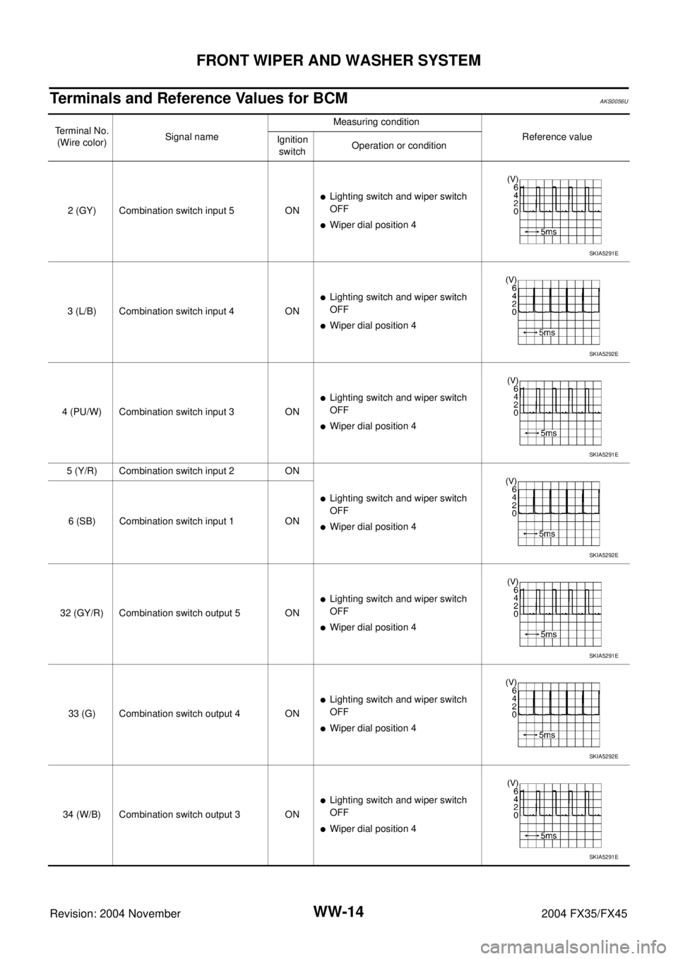
Terminals and Reference Values for BCMAKS0056U
Terminal No.
(Wire color)Signal nameMeasuring condition
Reference value
Ignition
switchOperation or condition
2 (GY) Combination switch input 5 ON
�Lighting switch and wiper switch
OFF
�Wiper dial position 4
3 (L/B) Combination switch input 4 ON
�Lighting switch and wiper switch
OFF
�Wiper dial position 4
4 (PU/W) Combination switch input 3 ON
�Lighting switch and wiper switch
OFF
�Wiper dial position 4
5 (Y/R) Combination switch input 2 ON
�Lighting switch and wiper switch
OFF
�Wiper dial position 4 6 (SB) Combination switch input 1 ON
32 (GY/R) Combination switch output 5 ON
�Lighting switch and wiper switch
OFF
�Wiper dial position 4
33 (G) Combination switch output 4 ON
�Lighting switch and wiper switch
OFF
�Wiper dial position 4
34 (W/B) Combination switch output 3 ON
�Lighting switch and wiper switch
OFF
�Wiper dial position 4
SKIA5291E
SKIA5292E
SKIA5291E
SKIA5292E
SKIA5291E
SKIA5292E
SKIA5291E
Page 4406 of 4449

FRONT WIPER AND WASHER SYSTEM
WW-15
C
D
E
F
G
H
I
J
L
MA
B
WW
Revision: 2004 November 2004 FX35/FX45
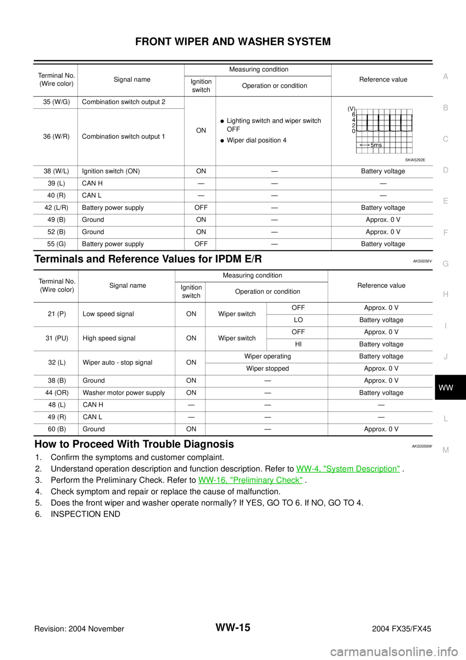
Terminals and Reference Values for IPDM E/RAKS0056V
How to Proceed With Trouble DiagnosisAKS0056W
1. Confirm the symptoms and customer complaint.
2. Understand operation description and function description. Refer to WW-4, "
System Description" .
3. Perform the Preliminary Check. Refer to WW-16, "
Preliminary Check" .
4. Check symptom and repair or replace the cause of malfunction.
5. Does the front wiper and washer operate normally? If YES, GO TO 6. If NO, GO TO 4.
6. INSPECTION END
35 (W/G) Combination switch output 2
ON
�Lighting switch and wiper switch
OFF
�Wiper dial position 4 36 (W/R) Combination switch output 1
38 (W/L) Ignition switch (ON) ON — Battery voltage
39 (L) CAN H — — —
40 (R) CAN L — — —
42 (L/R) Battery power supply OFF — Battery voltage
49 (B) Ground ON — Approx. 0 V
52 (B) Ground ON — Approx. 0 V
55 (G) Battery power supply OFF — Battery voltage Terminal No.
(Wire color)Signal nameMeasuring condition
Reference value
Ignition
switchOperation or condition
SKIA5292E
Terminal No.
(Wire color)Signal nameMeasuring condition
Reference value
Ignition
switchOperation or condition
21 (P) Low speed signal ON Wiper switchOFF Approx. 0 V
LO Battery voltage
31 (PU) High speed signal ON Wiper switchOFF Approx. 0 V
HI Battery voltage
32 (L) Wiper auto - stop signal ONWiper operating Battery voltage
Wiper stopped Approx. 0 V
38 (B) Ground ON — Approx. 0 V
44 (OR) Washer motor power supply ON — Battery voltage
48 (L) CAN H — — —
49 (R) CAN L — — —
60 (B) Ground ON — Approx. 0 V
Page 4430 of 4449

REAR WIPER AND WASHER SYSTEM
WW-39
C
D
E
F
G
H
I
J
L
MA
B
WW
Revision: 2004 November 2004 FX35/FX45
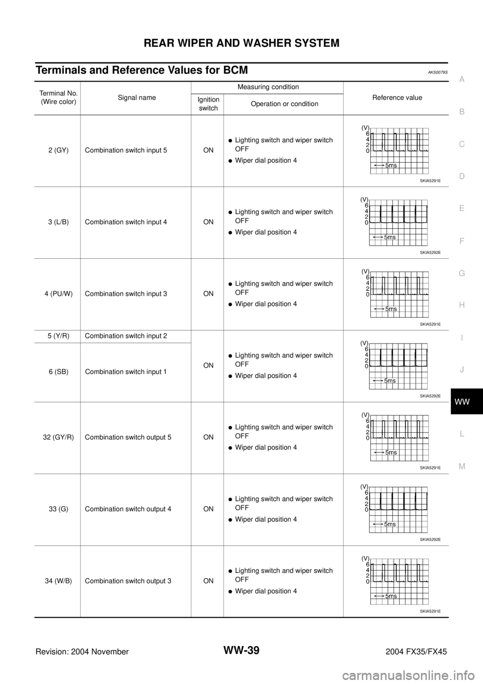
Terminals and Reference Values for BCMAKS0079S
Terminal No.
(Wire color)Signal nameMeasuring condition
Reference value
Ignition
switchOperation or condition
2 (GY) Combination switch input 5 ON
�Lighting switch and wiper switch
OFF
�Wiper dial position 4
3 (L/B) Combination switch input 4 ON
�Lighting switch and wiper switch
OFF
�Wiper dial position 4
4 (PU/W) Combination switch input 3 ON
�Lighting switch and wiper switch
OFF
�Wiper dial position 4
5 (Y/R) Combination switch input 2
ON
�Lighting switch and wiper switch
OFF
�Wiper dial position 4 6 (SB) Combination switch input 1
32 (GY/R) Combination switch output 5 ON
�Lighting switch and wiper switch
OFF
�Wiper dial position 4
33 (G) Combination switch output 4 ON
�Lighting switch and wiper switch
OFF
�Wiper dial position 4
34 (W/B) Combination switch output 3 ON
�Lighting switch and wiper switch
OFF
�Wiper dial position 4
SKIA5291E
SKIA5292E
SKIA5291E
SKIA5292E
SKIA5291E
SKIA5292E
SKIA5291E
Page 4431 of 4449

WW-40
REAR WIPER AND WASHER SYSTEM
Revision: 2004 November 2004 FX35/FX45
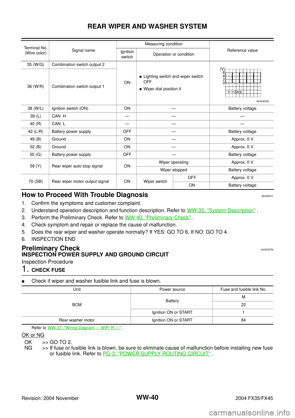
How to Proceed With Trouble DiagnosisAKS0057L
1. Confirm the symptoms and customer complaint.
2. Understand operation description and function description. Refer to WW-35, "
System Description" .
3. Perform the Preliminary Check. Refer to WW-40, "
Preliminary Check" .
4. Check symptom and repair or replace the cause of malfunction.
5. Does the rear wiper and washer operate normally? If YES: GO TO 6. If NO: GO TO 4.
6. INSPECTION END
Preliminary CheckAKS0057M
INSPECTION POWER SUPPLY AND GROUND CIRCUIT
Inspection Procedure
1. CHECK FUSE
�Check if wiper and washer fusible link and fuse is blown.
Refer to WW-37, "Wiring Diagram — WIP/ R —" .
OK or NG
OK >> GO TO 2.
NG >> If fuse or fusible link is blown, be sure to eliminate cause of malfunction before installing new fuse
or fusible link. Refer to PG-3, "
POWER SUPPLY ROUTING CIRCUIT" .
35 (W/G) Combination switch output 2
ON
�Lighting switch and wiper switch
OFF
�Wiper dial position 4 36 (W/R) Combination switch output 1
38 (W/L) Ignition switch (ON) ON — Battery voltage
39 (L) CAN H — — —
40 (R) CAN L — — —
42 (L/R) Battery power supply OFF — Battery voltage
49 (B) Ground ON — Approx. 0 V
52 (B) Ground ON — Approx. 0 V
55 (G) Battery power supply OFF — Battery voltage
59 (Y) Rear wiper auto stop signal ONWiper operating Approx. 0 V
Wiper stopped Battery voltage
70 (SB) Rear wiper motor output signal ON Wiper switchOFF Approx. 0 V
ON Battery voltage Terminal No.
(Wire color)Signal nameMeasuring condition
Reference value
Ignition
switchOperation or condition
SKIA5292E
Unit Power source Fuse and fusible link No.
BCMBatteryM
22
Ignition ON or START 1
Rear washer motor Ignition ON or START 84