2004 INFINITI FX35 seat heater switch
[x] Cancel search: seat heater switchPage 1348 of 4449

EC-7
C
D
E
F
G
H
I
J
K
L
M
ECA
Revision: 2004 November 2004 FX35/FX45Component Inspection ......................................... 575
Removal and Installation ...................................... 575
DTC P2138 APP SENSOR ..................................... 576
Component Description ........................................ 576
CONSULT-II Reference Value in Data Monitor Mode
. 576
On Board Diagnosis Logic ................................... 576
DTC Confirmation Procedure ............................... 577
Wiring Diagram .................................................... 578
Diagnostic Procedure ........................................... 579
Component Inspection ......................................... 584
Removal and Installation ...................................... 584
IGNITION SIGNAL .................................................. 585
Component Description ........................................ 585
Wiring Diagram .................................................... 586
Diagnostic Procedure ........................................... 591
Component Inspection ......................................... 595
Removal and Installation ...................................... 596
INJECTOR CIRCUIT ............................................... 597
Component Description ........................................ 597
CONSULT-II Reference Value in Data Monitor Mode
. 597
Wiring Diagram .................................................... 598
Diagnostic Procedure ........................................... 599
Component Inspection ......................................... 602
Removal and Installation ...................................... 602
FUEL PUMP CIRCUIT ............................................ 603
Description ........................................................... 603
CONSULT-II Reference Value in Data Monitor Mode
. 603
Wiring Diagram .................................................... 604
Diagnostic Procedure ........................................... 605
Component Inspection ......................................... 608
Removal and Installation ...................................... 608
REFRIGERANT PRESSURE SENSOR ................. 609
Component Description ........................................ 609
Wiring Diagram .................................................... 610
Diagnostic Procedure ............................................ 611
Removal and Installation ...................................... 613
ELECTRICAL LOAD SIGNAL ................................ 614
Description ........................................................... 614
CONSULT-II Reference Value in Data Monitor Mode
. 614
Diagnostic Procedure ........................................... 614
ICC BRAKE SWITCH ............................................. 615
Component Description ........................................ 615
CONSULT-II Reference Value in Data Monitor Mode
. 615
Wiring Diagram .................................................... 616
Diagnostic Procedure ........................................... 617
Component Inspection ......................................... 622
ASCD BRAKE SWITCH ......................................... 624
Component Description ........................................ 624
CONSULT-II Reference Value in Data Monitor Mode
. 624
Wiring Diagram .................................................... 625
Diagnostic Procedure ........................................... 626
Component Inspection ......................................... 631ASCD INDICATOR ..................................................632
Component Description ........................................632
CONSULT-II Reference Value in Data Monitor Mode
.632
Wiring Diagram .....................................................633
Diagnostic Procedure ...........................................634
SNOW MODE SWITCH ..........................................635
Description ............................................................635
CONSULT-II Reference Value in the Data Monitor
Mode .....................................................................635
Wiring Diagram .....................................................636
Diagnostic Procedure ...........................................637
Component Inspection ..........................................640
MIL AND DATA LINK CONNECTOR ......................641
Wiring Diagram .....................................................641
EVAPORATIVE EMISSION SYSTEM .....................643
Description ............................................................643
Component Inspection ..........................................646
Removal and Installation ......................................647
How to Detect Fuel Vapor Leakage ......................647
ON BOARD REFUELING VAPOR RECOVERY
(ORVR) ....................................................................650
System Description ...............................................650
Diagnostic Procedure ...........................................651
Component Inspection ..........................................653
POSITIVE CRANKCASE VENTILATION ...............655
Description ............................................................655
Component Inspection ..........................................655
AUTOMATIC SPEED CONTROL DEVICE (ASCD) .657
System Description ...............................................657
Component Description ........................................659
SERVICE DATA AND SPECIFICATIONS (SDS) ....660
Fuel Pressure .......................................................660
Idle Speed and Ignition Timing .............................660
Calculated Load Value ..........................................660
Mass Air Flow Sensor ...........................................660
Intake Air Temperature Sensor .............................660
Engine Coolant Temperature Sensor ...................660
Heated Oxygen Sensor 1 Heater .........................660
Heated Oxygen sensor 2 Heater ..........................660
Crankshaft Position Sensor (POS) .......................660
Camshaft Position Sensor (PHASE) ....................660
Throttle Control Motor ...........................................660
Injector ..................................................................661
Fuel Pump ............................................................661
VK45DE
INDEX FOR DTC .....................................................662
Alphabetical Index ................................................662
DTC No. Index ......................................................665
PRECAUTIONS ......................................................670
Precautions for Supplemental Restraint System
(SRS) “AIR BAG” and “SEAT BELT PRE-TEN-
SIONER” ...............................................................670
On Board Diagnostic (OBD) System of Engine and
A/T ........................................................................670
Precaution ............................................................670
Wiring Diagrams and Trouble Diagnosis ..............673
Page 3903 of 4449

PG-68
HARNESS
Revision: 2004 November 2004 FX35/FX45
H/AIM LT Headlamp Aiming Control System
H/LAMP LT Headlamp
HORN WW Horn
HSEAT SE Heated Seat
I/KEY BL Intelligent Key System
I/MIRR GW Inside Mirror (Auto Anti-Dazzling Mirror)
IATS EC Intake Air Temperature Sensor
ICC ACS Intelligent Cruise Control System
ICC/BS EC ICC Brake Switch
ICC/SW EC ICC Steering Switch
ICCBOF EC ICC Brake Switch
IGNSYS EC Ignition System
ILL LT Illumination
INF/D AV Vehicle Information and Integrated Switch System
INJECT EC Injector
IVCB1 EC Intake Valve Timing Control Solenoid Valve Bank 1
IVCB2 EC Intake Valve Timing Control Solenoid Valve Bank 2
IVCSB1 EC Intake Valve Timing Control Position Sensor Bank 1
IVCSB2 EC Intake Valve Timing Control Position Sensor Bank 2
IVTB1 EC Intake Valve Timing Control System (Bank 1)
IVTB2 EC Intake Valve Timing Control System (Bank 2)
KEYLES BL Remote Keyless Entry System
KS EC Knock Sensor
M/ANT AV Manual Antenna
MAFS EC Mass Air Flow Sensor
MAIN EC Main Power Supply And Ground Circuit
MES AV Mobile Entertainment System
METER DI Speedometer, Tachometer, Temp., And Fuel Gauges
MIL/DL EC Mil&Data Link Connectors
MIRROR GW Power Door Mirror
MMSW AT Manual Mode Switch
NATS BL Nissan Anti - Theft System
NAVI AV Navigation System
NONDTC AT Non-Detective Items
O2H1B1 EC Heated Oxygen Sensor 1 Heater Bank 1
O2H1B2 EC Heated Oxygen Sensor 1 Heater Bank 2
O2H2B1 EC Heated Oxygen Sensor 2 Heater Bank 1
O2H2B2 EC Heated Oxygen Sensor 2 Heater Bank 2
O2S1B1 EC Heated Oxygen Sensor 1 Bank 1
O2S1B2 EC Heated Oxygen Sensor 1 Bank 2
O2S2B1 EC Heated Oxygen Sensor 2 Bank 1
O2S2B2 EC Heated Oxygen Sensor 2 Bank 2
P/SCKT WW Power Socket
PGC/V EC Evap Canister Purge Volume Control Solenoid Valve Code Section Wiring Diagram Name
Page 4235 of 4449

SE-106
FRONT SEAT
Revision: 2004 November 2004 FX35/FX45
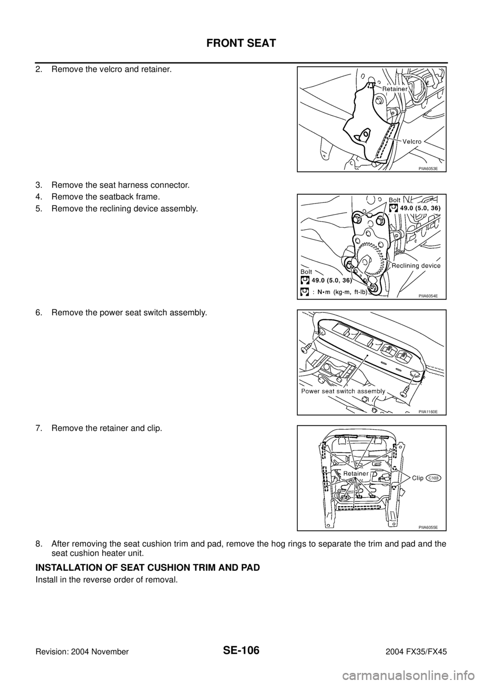
2. Remove the velcro and retainer.
3. Remove the seat harness connector.
4. Remove the seatback frame.
5. Remove the reclining device assembly.
6. Remove the power seat switch assembly.
7. Remove the retainer and clip.
8. After removing the seat cushion trim and pad, remove the hog rings to separate the trim and pad and the
seat cushion heater unit.
INSTALLATION OF SEAT CUSHION TRIM AND PAD
Install in the reverse order of removal.
PIIA6053E
PIIA6054E
PIIA1160E
PIIA6055E