Page 3647 of 4449
LT-92
TURN SIGNAL AND HAZARD WARNING LAMPS
Revision: 2004 November 2004 FX35/FX45
Connected form BCM terminals 45 and 46 to rear combination lamp control unit terminals 4 and 5,
rear turn signal (LED) turns on
�through rear combination lamp control unit terminal 11
�to rear combination lamp LH terminal 3
�through rear combination lamp LH terminal 4
�to rear combination lamp control unit terminal 10
�through rear combination lamp control unit terminal 9
�to rear combination lamp RH terminal 3
�through rear combination lamp RH terminal 4
�to rear combination lamp control unit terminal 8.
BCM sends signal to unified meter and A/C amp. through CAN communication lines, and turns on turn signal
indicator lamp with combination meter.
With power and input supplied, the BCM controls the flashing of the hazard warning lamps when keyfob is
used to activate the remote control entry system.
COMBINATION SWITCH READING FUNCTION
Refer to BCS-3, "COMBINATION SWITCH READING FUNCTION" .
CAN Communication System DescriptionAKS007CX
CAN (Controller Area Network) is a serial communication line for real time application. It is an on-vehicle mul-
tiplex communication line with high data communication speed and excellent error detection ability. Many elec-
tronic control units are equipped onto a vehicle, and each control unit shares information and links with other
control units during operation (not independent). In CAN communication, control units are connected with 2
communication lines (CAN H line, CAN L line) allowing a high rate of information transmission with less wiring.
Each control unit transmits/receives data but selectively reads required data only.
CAN Communication UnitAKS0080W
Refer to LAN-6, "CAN Communication Unit" .
Page 3654 of 4449
TURN SIGNAL AND HAZARD WARNING LAMPS
LT-99
C
D
E
F
G
H
I
J
L
MA
B
LT
Revision: 2004 November 2004 FX35/FX45
Preliminary CheckAKS007D3
CHECK POWER SUPPLY AND GROUND CIRCUIT
1. CHECK FUSES
�Check fuses for blown-out.
Refer to LT-94, "Wiring Diagram — TURN —" .
OK or NG
OK >> GO TO 2.
NG >> If fuse is blown, be sure to eliminate cause of malfunction before installing new fuse. Refer to PG-
3, "POWER SUPPLY ROUTING CIRCUIT" .
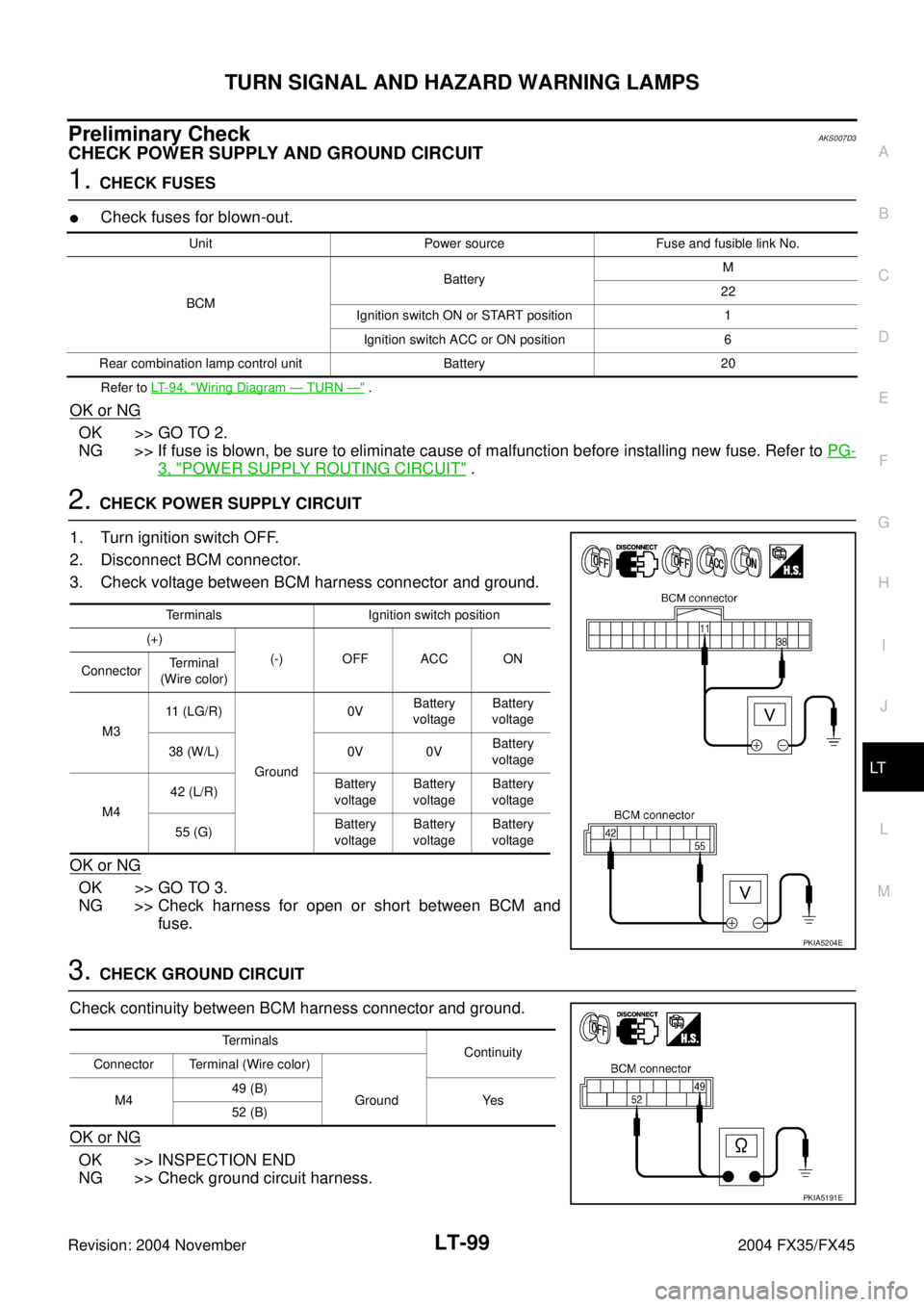
2. CHECK POWER SUPPLY CIRCUIT
1. Turn ignition switch OFF.
2. Disconnect BCM connector.
3. Check voltage between BCM harness connector and ground.
OK or NG
OK >> GO TO 3.
NG >> Check harness for open or short between BCM and
fuse.
3. CHECK GROUND CIRCUIT
Check continuity between BCM harness connector and ground.
OK or NG
OK >> INSPECTION END
NG >> Check ground circuit harness.
Unit Power source Fuse and fusible link No.
BCMBatteryM
22
Ignition switch ON or START position 1
Ignition switch ACC or ON position 6
Rear combination lamp control unit Battery 20
Terminals Ignition switch position
(+)
(-) OFF ACC ON
ConnectorTerminal
(Wire color)
M311 (LG/R)
Ground0VBattery
voltageBattery
voltage
38 (W/L) 0V 0VBattery
voltage
M442 (L/R)Battery
voltageBattery
voltageBattery
voltage
55 (G)Battery
voltageBattery
voltageBattery
voltage
PKIA5204E
Terminals
Continuity
Connector Terminal (Wire color)
M449 (B)
Ground Yes
52 (B)
PKIA5191E
Page 3655 of 4449
LT-100
TURN SIGNAL AND HAZARD WARNING LAMPS
Revision: 2004 November 2004 FX35/FX45
CONSULT-II FunctionsAKS007D4
CONSULT-II has a display function for work support, self-diagnosis, data monitor, and active test for each part
by combining data receiving and sending via the communication line from BCM.
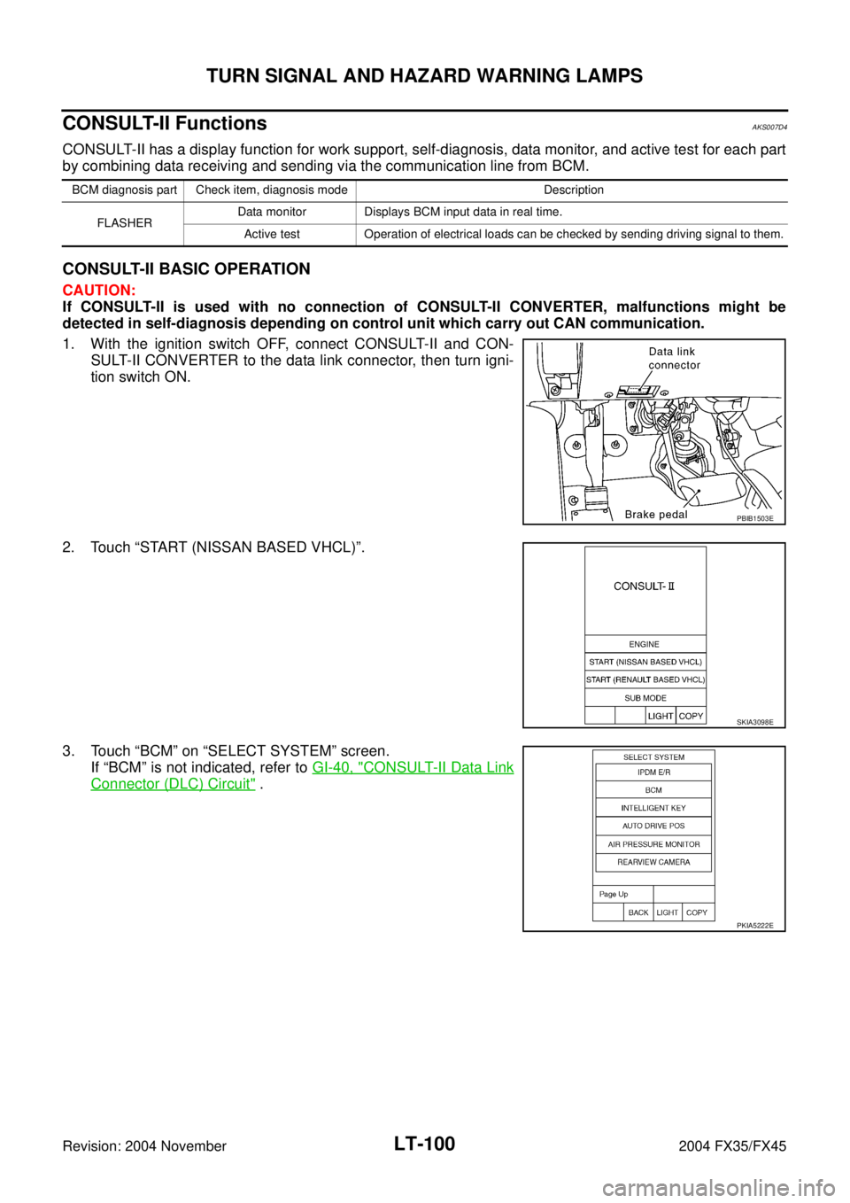
CONSULT-II BASIC OPERATION
CAUTION:
If CONSULT-II is used with no connection of CONSULT-II CONVERTER, malfunctions might be
detected in self-diagnosis depending on control unit which carry out CAN communication.
1. With the ignition switch OFF, connect CONSULT-II and CON-
SULT-II CONVERTER to the data link connector, then turn igni-
tion switch ON.
2. Touch “START (NISSAN BASED VHCL)”.
3. Touch “BCM” on “SELECT SYSTEM” screen.
If “BCM” is not indicated, refer to GI-40, "
CONSULT-II Data Link
Connector (DLC) Circuit" .
BCM diagnosis part Check item, diagnosis mode Description
FLASHERData monitor Displays BCM input data in real time.
Active test Operation of electrical loads can be checked by sending driving signal to them.
PBIB1503E
SKIA3098E
PKIA5222E
Page 3659 of 4449
LT-104
TURN SIGNAL AND HAZARD WARNING LAMPS
Revision: 2004 November 2004 FX35/FX45
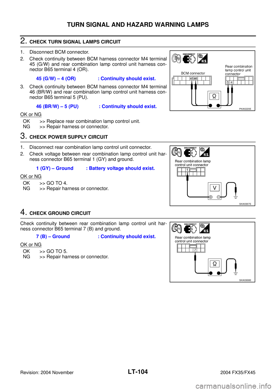
2. CHECK TURN SIGNAL LAMPS CIRCUIT
1. Disconnect BCM connector.
2. Check continuity between BCM harness connector M4 terminal
45 (G/W) and rear combination lamp control unit harness con-
nector B65 terminal 4 (OR).
3. Check continuity between BCM harness connector M4 terminal
46 (BR/W) and rear combination lamp control unit harness con-
nector B65 terminal 5 (PU).
OK or NG
OK >> Replace rear combination lamp control unit.
NG >> Repair harness or connector.
3. CHECK POWER SUPPLY CIRCUIT
1. Disconnect rear combination lamp control unit connector.
2. Check voltage between rear combination lamp control unit har-
ness connector B65 terminal 1 (GY) and ground.
OK or NG
OK >> GO TO 4.
NG >> Repair harness or connector.
4. CHECK GROUND CIRCUIT
Check continuity between rear combination lamp control unit har-
ness connector B65 terminal 7 (B) and ground.
OK or NG
OK >> GO TO 5.
NG >> Repair harness or connector.45 (G/W) – 4 (OR) : Continuity should exist.
46 (BR/W) – 5 (PU) : Continuity should exist.
PKIA5220E
1 (GY) – Ground : Battery voltage should exist.
SKIA5907E
7 (B) – Ground : Continuity should exist.
SKIA5908E
Page 3660 of 4449
TURN SIGNAL AND HAZARD WARNING LAMPS
LT-105
C
D
E
F
G
H
I
J
L
MA
B
LT
Revision: 2004 November 2004 FX35/FX45
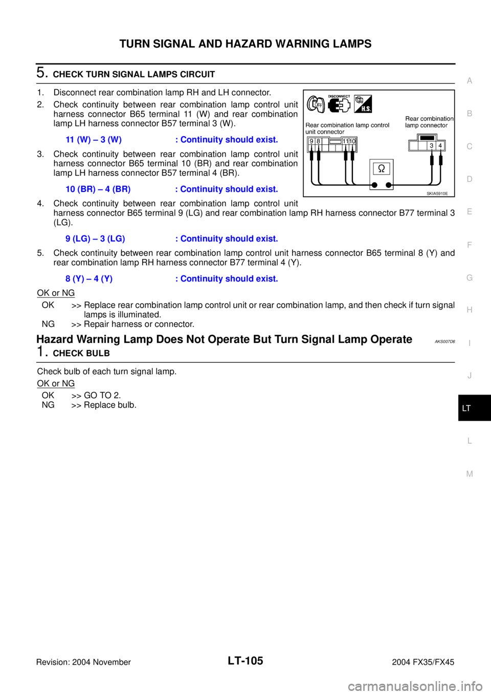
5. CHECK TURN SIGNAL LAMPS CIRCUIT
1. Disconnect rear combination lamp RH and LH connector.
2. Check continuity between rear combination lamp control unit
harness connector B65 terminal 11 (W) and rear combination
lamp LH harness connector B57 terminal 3 (W).
3. Check continuity between rear combination lamp control unit
harness connector B65 terminal 10 (BR) and rear combination
lamp LH harness connector B57 terminal 4 (BR).
4. Check continuity between rear combination lamp control unit
harness connector B65 terminal 9 (LG) and rear combination lamp RH harness connector B77 terminal 3
(LG).
5. Check continuity between rear combination lamp control unit harness connector B65 terminal 8 (Y) and
rear combination lamp RH harness connector B77 terminal 4 (Y).
OK or NG
OK >> Replace rear combination lamp control unit or rear combination lamp, and then check if turn signal
lamps is illuminated.
NG >> Repair harness or connector.
Hazard Warning Lamp Does Not Operate But Turn Signal Lamp OperateAKS007D6
1. CHECK BULB
Check bulb of each turn signal lamp.
OK or NG
OK >> GO TO 2.
NG >> Replace bulb.11 (W) – 3 (W) : Continuity should exist.
10 (BR) – 4 (BR) : Continuity should exist.
9 (LG) – 3 (LG) : Continuity should exist.
8 (Y) – 4 (Y) : Continuity should exist.
SKIA5910E
Page 3662 of 4449
TURN SIGNAL AND HAZARD WARNING LAMPS
LT-107
C
D
E
F
G
H
I
J
L
MA
B
LT
Revision: 2004 November 2004 FX35/FX45
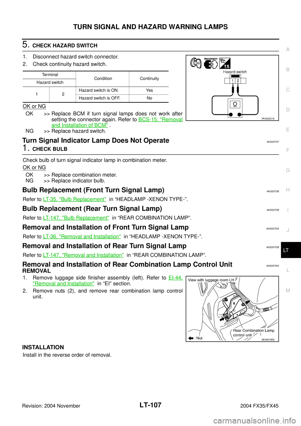
5. CHECK HAZARD SWITCH
1. Disconnect hazard switch connector.
2. Check continuity hazard switch.
OK or NG
OK >> Replace BCM if turn signal lamps does not work after
setting the connector again. Refer to BCS-15, "
Removal
and Installation of BCM" .
NG >> Replace hazard switch.
Turn Signal Indicator Lamp Does Not OperateAKS007D7
1. CHECK BULB
Check bulb of turn signal indicator lamp in combination meter.
OK or NG
OK >> Replace combination meter.
NG >> Replace indicator bulb.
Bulb Replacement (Front Turn Signal Lamp)AKS007D8
Refer to LT- 3 5 , "Bulb Replacement" in “HEADLAMP -XENON TYPE-”.
Bulb Replacement (Rear Turn Signal Lamp)AKS007D9
Refer to LT- 1 4 7 , "Bulb Replacement" in “REAR COMBINATION LAMP”.
Removal and Installation of Front Turn Signal LampAKS007DA
Refer to LT- 3 6 , "Removal and Installation" in “HEADLAMP -XENON TYPE-”.
Removal and Installation of Rear Turn Signal Lamp AKS007DB
Refer to LT- 1 4 7 , "Removal and Installation" in “REAR COMBINATION LAMP”.
Removal and Installation of Rear Combination Lamp Control UnitAKS007NX
REMOVAL
1. Remove luggage side finisher assembly (left). Refer to EI-44,
"Removal and Installation" in “EI” section.
2. Remove nuts (2), and remove rear combination lamp control
unit.
INSTALLATION
Install in the reverse order of removal.
Te r m i n a l
Condition Continuity
Hazard switch
12Hazard switch is ON. Yes
Hazard switch is OFF. No
PKIA5221E
SKIA6185E
Page 3666 of 4449
COMBINATION SWITCH
LT-111
C
D
E
F
G
H
I
J
L
MA
B
LT
Revision: 2004 November 2004 FX35/FX45
Combination Switch Reading FunctionAKS007G5
For details, refer to BCS-3, "COMBINATION SWITCH READING FUNCTION" in “BCS” section.
CONSULT-II FunctionAKS007G6
CONSULT-II has a display function for work support, self-diagnosis, data monitor, and active test for each part
by combining data receiving and sending via the communication line from BCM.
CONSULT-II BASIC OPERATION
CAUTION:
If CONSULT-II is used with no connection of CONSULT-II CONVERTER, malfunctions might be
detected in self-diagnosis depending on control unit which carry out CAN communication.
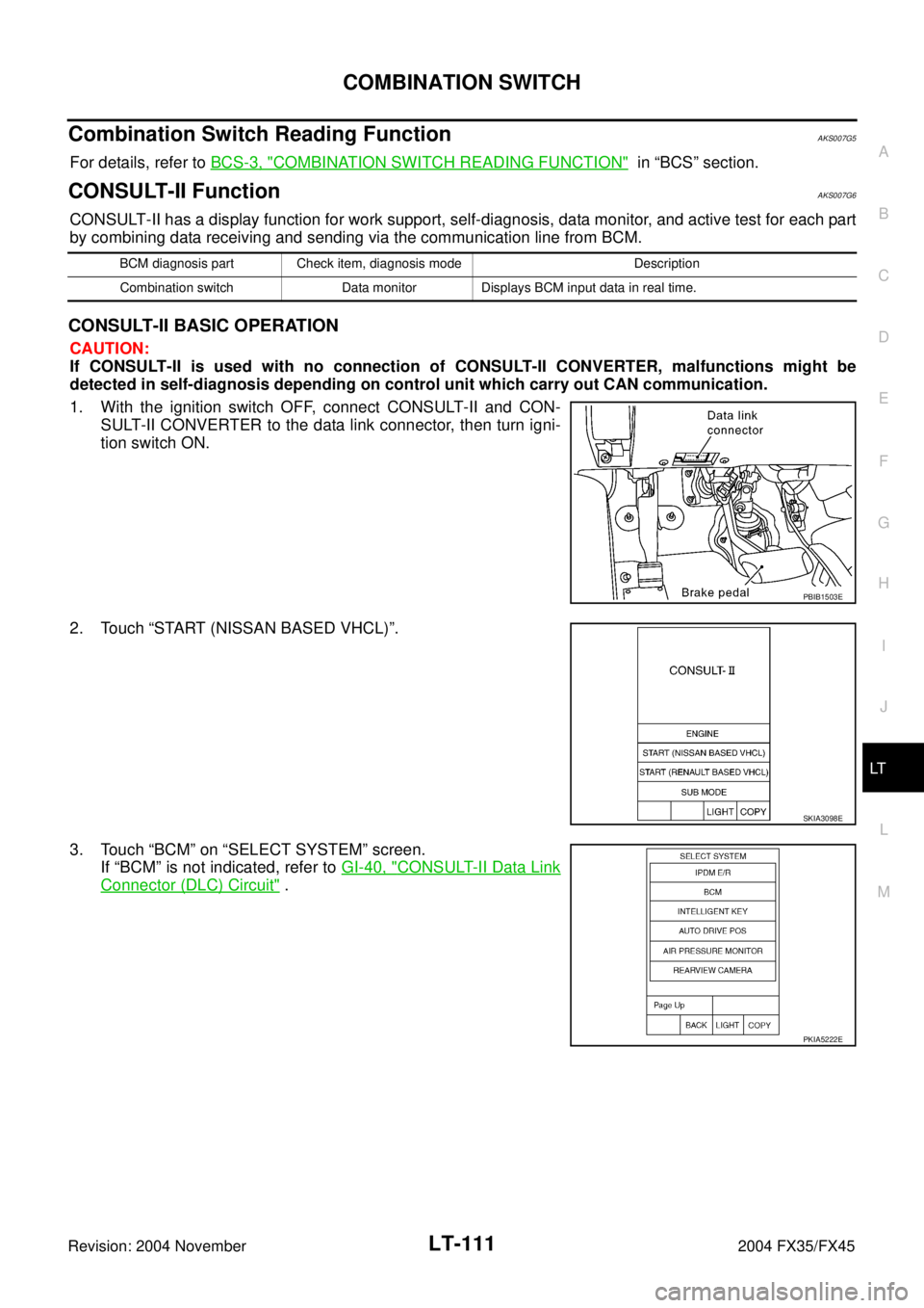
1. With the ignition switch OFF, connect CONSULT-II and CON-
SULT-II CONVERTER to the data link connector, then turn igni-
tion switch ON.
2. Touch “START (NISSAN BASED VHCL)”.
3. Touch “BCM” on “SELECT SYSTEM” screen.
If “BCM” is not indicated, refer to GI-40, "
CONSULT-II Data Link
Connector (DLC) Circuit" .
BCM diagnosis part Check item, diagnosis mode Description
Combination switch Data monitor Displays BCM input data in real time.
PBIB1503E
SKIA3098E
PKIA5222E
Page 3668 of 4449
COMBINATION SWITCH
LT-113
C
D
E
F
G
H
I
J
L
MA
B
LT
Revision: 2004 November 2004 FX35/FX45
Combination Switch InspectionAKS007G7
1. SYSTEM CHECK
1. Referring to table below, check which system malfunctioning switch belongs to.
>> Check the system to which malfunctioning switch belongs, and GO TO 2.
2. SYSTEM CHECK
With CONSULT-II
CAUTION:
If CONSULT-II is used with no connection of CONSULT-II CONVERTER, malfunctions might be
detected in self-diagnosis depending on control unit which carry out CAN communication.
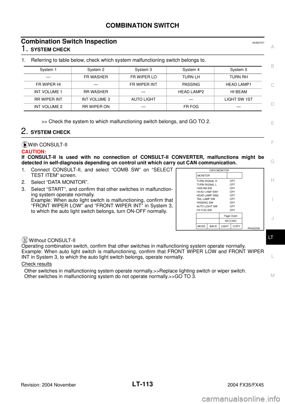
1. Connect CONSULT-II, and select “COMB SW” on “SELECT
TEST ITEM” screen.
2. Select “DATA MONITOR”.
3. Select “START”, and confirm that other switches in malfunction-
ing system operate normally.
Example: When auto light switch is malfunctioning, confirm that
“FRONT WIPER LOW” and “FRONT WIPER INT” in System 3,
to which the auto light switch belongs, turn ON-OFF normally.
Without CONSULT-II
Operating combination switch, confirm that other switches in malfunctioning system operate normally.
Example: When auto light switch is malfunctioning, confirm that FRONT WIPER LOW and FRONT WIPER
INT in System 3, to which the auto light switch belongs, operate normally.
Check results
Other switches in malfunctioning system operate normally.>>Replace lighting switch or wiper switch.
Other switches in malfunctioning system do not operate normally.>>GO TO 3.
System 1 System 2 System 3 System 4 System 5
— FR WASHER FR WIPER LO TURN LH TURN RH
FR WIPER HI — FR WIPER INT PASSING HEAD LAMP1
INT VOLUME 1 RR WASHER — HEAD LAMP2 HI BEAM
RR WIPER INT INT VOLUME 3 AUTO LIGHT — LIGHT SW 1ST
INT VOLUME 2 RR WIPER ON — FR FOG —
PKIA5224E