Page 2971 of 4449
![INFINITI FX35 2004 Service Manual EM-246
[VK45DE]
CYLINDER BLOCK
Revision: 2004 November 2004 FX35/FX45
�Press-fit pilot converter with its chamfering side facing crank-
shaft as shown in the figure.
�It is possible to remove pilot co](/manual-img/42/57021/w960_57021-2970.png "INFINITI FX35 2004 Service Manual EM-246
[VK45DE]
CYLINDER BLOCK
Revision: 2004 November 2004 FX35/FX45
�Press-fit pilot converter with its chamfering side facing crank-
shaft as shown in the figure.
�It is possible to remove pilot co")
EM-246
[VK45DE]
CYLINDER BLOCK
Revision: 2004 November 2004 FX35/FX45
�Press-fit pilot converter with its chamfering side facing crank-
shaft as shown in the figure.
�It is possible to remove pilot converter without hoisting engine
with engine stand.
5. Install crankshaft to cylinder block.
�While turning crankshaft by hand, make sure it turns smoothly.
6. Install main bearing caps.
�Align the identification number to the journal position to install.
�Install the upper side of the identification number facing the
front of engine. (The number shall be read correctly from the
rear of engine.)
�Using plastic hammer or similar tool, tap them lightly to seat
them on the installation position.
NOTE:
Main bearing cap cannot be replaced as a single parts, because
it is machined together with cylinder block.
7. Install each main bearing cap bolt as follows:
a. Apply new engine oil to threads and seating surface of main
bearing cap bolts, and tighten all bolts temporarily.
b. Tighten main bearing cap bolt (M12) in order of 1 to 10.
c. Tighten main bearing cap sub bolt (M9) in order of 11 to 20.
d. Tighten main bearing cap bolt (M12) to 40 degrees clockwise in
order of 1 to 10. (Angle tightening)
CAUTION:
Use angle wrench (SST) to check tightening angle in step
“d” and “e”. Do not make judgment by visual inspection.
e. Tighten main bearing cap sub bolt (M9) to 30 degrees clockwise
in order of 11 to 20. (Angle tightening)
f. Tighten side bolt (M10) in order of 21 to 30.
�After installing main bearing cap bolts, make sure that crankshaft can be rotated smoothly.
�Check the crankshaft end play. Refer to EM-256, "CRANKSHAFT END PLAY" .
g. Install cover of cylinder block rear left side (next to the starter motor housing).
SEM537E
PBIC0095E
: 39.2 N·m (4.0 kg-m, 29 ft-lb)
: 29.4 N·m (3.0 kg-m, 22 ft-lb)
PBIC0090E
PBIC0096E
: 49 N·m (5.0 kg-m, 36 ft-lb)
Page 2974 of 4449
![INFINITI FX35 2004 Service Manual CYLINDER BLOCK
EM-249
[VK45DE]
C
D
E
F
G
H
I
J
K
L
MA
EM
Revision: 2004 November 2004 FX35/FX45
15. Tighten the connecting rod nuts as follows:
a. Apply engine oil to the threads and seats of connecti](/manual-img/42/57021/w960_57021-2973.png "INFINITI FX35 2004 Service Manual CYLINDER BLOCK
EM-249
[VK45DE]
C
D
E
F
G
H
I
J
K
L
MA
EM
Revision: 2004 November 2004 FX35/FX45
15. Tighten the connecting rod nuts as follows:
a. Apply engine oil to the threads and seats of connecti")
CYLINDER BLOCK
EM-249
[VK45DE]
C
D
E
F
G
H
I
J
K
L
MA
EM
Revision: 2004 November 2004 FX35/FX45
15. Tighten the connecting rod nuts as follows:
a. Apply engine oil to the threads and seats of connecting rod bolts
and nuts.
b. Tighten nuts.
c. Then tighten all nuts 60 degrees clockwise. (Angle tightening)
CAUTION:
Use angle wrench (SST) to check tightening angle. Do not
make judgment by visual inspection.
�After tightening nuts, make sure that the crankshaft rotates
smoothly.
�Check the connecting rod side clearance. Refer to EM-256, "CONNECTING ROD SIDE CLEARANCE"
.
16. Install knock sensor.
�Install it with its connector facing the rear of engine.
�Install the sub-harness with its shorter branch line to the right
bank.
CAUTION:
�Do not tighten mounting bolts while holding connector.
�If any impact by dropping is applied to knock sensor,
replace it with new one.
NOTE:
�Make sure that there is no foreign material on the cylinder
block mating surface and the back surface of the knock sen-
sor.
�Make sure that the knock sensor does not interfere with other parts.
17. Install in the reverse order of removal after this step.
18. Remove engine assembly from engine stand.
19. Install drive plate.
�Align guide pin of crankshaft rear end with pin holes of each
parts to install.
�Install drive plate, reinforcement plate and pilot converter (if
not installed in step 4) as shown in the figure.
�Face chamfered or rounded edge side to crankshaft.
�Holding ring gear with ring gear stopper [SST: J-45476].
�Tighten mounting bolts crosswise over several times.
�When install pilot converter, using drift [outer diameter:
approx. 35 mm (1.38 in)]. Press-fit as far as it will go. : 14.7 N·m (1.5 kg-m, 11 ft-lb)
PBIC0104E
PBIC0105E
PBIC0106E
PBIC1965E
Page 2995 of 4449
![INFINITI FX35 2004 Service Manual EM-270
[VK45DE]
SERVICE DATA AND SPECIFICATIONS (SDS)
Revision: 2004 November 2004 FX35/FX45
Valve Dimensions
Unit: mm (in)
Valve Guide
Unit: mm (in) Valve head diameter “D” Intake 36.0 - 36.3 (1.](/manual-img/42/57021/w960_57021-2994.png "INFINITI FX35 2004 Service Manual EM-270
[VK45DE]
SERVICE DATA AND SPECIFICATIONS (SDS)
Revision: 2004 November 2004 FX35/FX45
Valve Dimensions
Unit: mm (in)
Valve Guide
Unit: mm (in) Valve head diameter “D” Intake 36.0 - 36.3 (1.")
EM-270
[VK45DE]
SERVICE DATA AND SPECIFICATIONS (SDS)
Revision: 2004 November 2004 FX35/FX45
Valve Dimensions
Unit: mm (in)
Valve Guide
Unit: mm (in) Valve head diameter “D” Intake 36.0 - 36.3 (1.417 - 1.429)
Exhaust 31.2 - 31.5 (1.228 - 1.240)
Valve length “L”Intake 96.57 (3.8020)
Exhaust 94.50 (3.720)
Valve stem diameter “d”Intake 5.972 - 5.980 (0.2351 - 0.2354)
Exhaust 5.962 - 5.970 (0.2347 - 0.2350)
Valve seat angle “α”Intake
45°15′ - 45°45′
Exhaust
Valve margin “T”Intake 1.15 - 1.45 (0.0453 - 0.0571)
Exhaust 1.85 - 2.15 (0.0728 - 0.0846)
SEM188
ItemsStandard 0.2 (0.008) Oversize (Service)
Valve guideOuter diameter10.023 - 10.034 (0.3946 -
0.3950)10.223 - 10.234 (0.4025 -
0.4029)
Inner diameter (Finished size) 6.000 - 6.018 (0.2362 - 0.2369)
Cylinder head valve guide hole diameter 9.975 - 9.996 (0.3927 - 0.3935)10.175 - 10.196 (0.4006 -
0.4014)
Interference fit of valve guide 0.027 - 0.059 (0.0011 - 0.0023)
ItemsStandard Limit
Valve guide clearanceIntake 0.020 - 0.046 (0.0008 - 0.0018) 0.08 (0.003)
Exhaust 0.030 - 0.056 (0.0012 - 0.0022) 0.1 (0.004)
Projection length “L”Intake 10.1 - 10.3 (0.398 - 0.406) —
Exhaust 10.0 - 10.4 (0.394 - 0.409) —
PBIC0184E
Page 2996 of 4449
SERVICE DATA AND SPECIFICATIONS (SDS)
EM-271
[VK45DE]
C
D
E
F
G
H
I
J
K
L
MA
EM
Revision: 2004 November 2004 FX35/FX45
Valve Seat
Unit: mm (in)
Valve Spring
Items Standard Service
Cylinder head seat recess diameter “D”Intake 37.000 - 37.016 (1.4567 - 1.4573) 37.500 - 37.516 (1.4764 - 1.4770)
Exhaust 32.200 - 32.216 (1.2677 - 1.2683) 32.700 - 32.716 (1.2874 - 1.2880)
Valve seat interference fitIntake 0.081 - 0.113 (0.0032 - 0.0044)
Exhaust 0.064 - 0.096 (0.0025 - 0.0038)
Valve seat outer diameter “d”Intake 37.097 - 37.113 (1.4605 - 1.4611) 37.597 - 37.613 (1.4802 - 1.4808)
Exhaust 32.280 - 32.296 (1.2709 - 1.2715) 32.780 - 32.796 (1.2905 - 1.2912)
PBIC2379E
Free height mm (in) 46.35 - 46.85 (1.8247 - 1.8444)
Pressure N (kg, lb) at height mm (in)Installation 165 - 189 (16.8 - 19.3, 37 - 42) at 33.8 (1.331)
Valve open 290 - 330 (29.6 - 33.7, 65 - 74) at 24.4 (0.961)
Out-of-square mm (in) Limit 2.0 (0.079)
Page 3043 of 4449
FFD-8
FRONT OIL SEAL
Revision: 2004 November 2004 FX35/FX45
INSTALLATION
1. Apply multi-purpose grease to sealing lips of the oil seal. Drive
the oil seal into the differential case using special service tool so
that the oil seal flush with the gear carrier end.
NOTE:
�When installing the front oil seal, be careful not to get it
inclined.
�Discard the old front oil seal. Always replace it with a new
one.
2. Install the companion flange while align the matching mark of
the drive pinion with the matching mark B of the companion
flange.
3. Apply oil to the drive pinion threads and the seating surface of
drive pinion lock nut.
4. Using the drive pinion flange wrench. Install drive pinion lock nut
with tool.
CAUTION:
Do not reuse the drive pinion lock nut. Always replace it
with a new one.
5. Install the front propeller shaft. Refer to PR-5, "
INSTALLATION"
.Tool number A : ST33400001 (J26082)
B : KV38102510 ( – )
SDIA1645E
SDIA1609E
Tool number : KV40104000 ( – )
SDIA1647E
Page 3055 of 4449

FFD-20
FRONT FINAL DRIVE ASSEMBLY
Revision: 2004 November 2004 FX35/FX45
4. Turn the companion flange in both direction 20 times or more to
seat the bearing rollers.
5. Check total preload with special service tool.
�If the preload value is out of standard, adjust pinion bearing
preload and side bearing preload.
Drive Gear to Drive Pinion Gear Backlash
Set the dial indicator to the drive gear face and measure the back-
lash.
If the measured value is out of standard, adjust the backlash by
replacing the side bearing adjusting shim (differential case side).
�If the backlash too large, decrease side bearing adjusting shim
thickness.
�If the backlash too small, increase side bearing adjusting shim
thickness.
Drive Gear Runout
1. Set dial gauge to behind the drive gear and measure the ring gear runout.
a. If the runout is exceed limit, check for drive gear assembly:
�any object between the drive gear and differential case
�deformed differential case
�deformed drive gear
b. If drive gear is deformed, replace the drive gear and pinion gear as a set. If the differential case is
deformed, replace the differential case.
Companion Flange Runout
1. Set the dial gauge to the companion flange face and measure
runout.
2. Set the dial gauge to the inside face of the companion flange
and measure the runout.
CAUTION:
Clean inside face of companion flange before measuring
runout.
a. If runout is out side limit, remove the companion from the drive
pinion. Turn the companion flange position 90° each, and measure the runout again.
b. If runout valve still out side of the limit, replace companion flange.Tool number : ST3127S000 (see J25765-A)
Total preload : 1.56 - 2.65 N·m
(0.16 - 0.27 kg-m, 14 - 23 in-lb)
SDIA1649E
If the preload value too large : Decrease the drive pinion bearing adjusting washer thickness.
: Decrease the drive pinion adjusting washer thickness.
: Increase the side bearing adjusting shim thickness.
If the preload value too small : Increase the drive pinion bearing adjusting washer thickness.
: Increase the drive pinion adjusting washer thickness.
: Decrease the side bearing adjusting shim thickness.
Standard drive gear backlash
: 0.10 - 0.15 mm(0.0039 - 0.0059) in
SDIA0009J
Runout limit : 0.05 mm (0.0020 in) or less
Runout limit : 0.18 mm (0.007 in) or less
Runout limit : 0.13 mm (0.005 in) or less
SDIA1651E
Page 3061 of 4449
FFD-26
FRONT FINAL DRIVE ASSEMBLY
Revision: 2004 November 2004 FX35/FX45
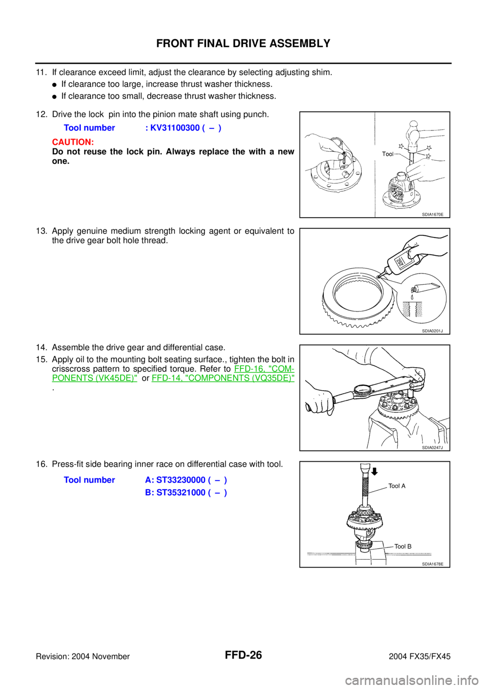
11. If clearance exceed limit, adjust the clearance by selecting adjusting shim.
�If clearance too large, increase thrust washer thickness.
�If clearance too small, decrease thrust washer thickness.
12. Drive the lock pin into the pinion mate shaft using punch.
CAUTION:
Do not reuse the lock pin. Always replace the with a new
one.
13. Apply genuine medium strength locking agent or equivalent to
the drive gear bolt hole thread.
14. Assemble the drive gear and differential case.
15. Apply oil to the mounting bolt seating surface., tighten the bolt in
crisscross pattern to specified torque. Refer to FFD-16, "
COM-
PONENTS (VK45DE)" or FFD-14, "COMPONENTS (VQ35DE)"
.
16. Press-fit side bearing inner race on differential case with tool.Tool number : KV31100300 ( – )
SDIA1670E
SDIA0201J
SDIA0247J
Tool number A: ST33230000 ( – )
B: ST35321000 ( – )
SDIA1678E
Page 3063 of 4449

FFD-28
FRONT FINAL DRIVE ASSEMBLY
Revision: 2004 November 2004 FX35/FX45
CAUTION:
Do not install the drive pinion adjusting washer and drive pinion bearing adjusting washer at this
time.
c. Install the companion flange without installing oil seal.
d. Apply oil drive pinion lock nut threads and seating surface, then temporarily install it.
e. Tighten the drive pinion lock nut until it reach standard preload.
CAUTION:
Tighten the drive pinion nut by very small degrees until the
specified preload in achieved. Do not tighten nut more than
necessary.
DIFFERENTIAL CASE INSTALLATION
1. Drive side bearing outer race into the carrier case with tool.
CAUTION:
Do not apply excessive force to the race.
2. Drive side bearing outer race into the side retainer with tool.
3. Apply oil to the bearing portion.
4. Install the deferential case assembly to the carrier case.
CAUTION:
Be careful not to damage the carrier cover mating surface.
5. Install the side bearing adjusting shim to the side retainer, tighten the bolt to specified torque.
CAUTION:
Install removed adjusting shim or same thickness shim.
NOTE:
Do not install O-ring.Tool number : KV40104000(−)
Pinion bearing preload without oil seal
: 0.78 - 1.57 N·m (0.08 - 0.16 kg-m, 7 - 13 in-lb)
SDIA1669E
Tool number : KV31103000 ( – )
SDIA1680E
Tool number : KV31103000 ( – )
SDIA1679E
![INFINITI FX35 2004 Service Manual SERVICE DATA AND SPECIFICATIONS (SDS)
EM-271
[VK45DE]
C
D
E
F
G
H
I
J
K
L
MA
EM
Revision: 2004 November 2004 FX35/FX45
Valve Seat
Unit: mm (in)
Valve Spring
Items Standard Service
Cylinder head seat r](/manual-img/42/57021/w960_57021-2995.png "INFINITI FX35 2004 Service Manual SERVICE DATA AND SPECIFICATIONS (SDS)
EM-271
[VK45DE]
C
D
E
F
G
H
I
J
K
L
MA
EM
Revision: 2004 November 2004 FX35/FX45
Valve Seat
Unit: mm (in)
Valve Spring
Items Standard Service
Cylinder head seat r")