Page 1103 of 4449
BR-10
BRAKE FLUID
Revision: 2004 November 2004 FX35/FX45
Bleeding Brake SystemAFS001MX
CAUTION:
While bleeding, pay attention to master cylinder fluid level.
1. Turn ignition switch OFF and disconnect ABS actuator and electric unit (control unit) connector or battery
negative terminal.
2. Connect a vinyl tube to the rear right bleed valve.
3. Fully depress brake pedal 4 to 5 times.
4. With brake pedal depressed, loosen bleed valve to let the air out, and then tighten it immediately.
5. Repeat steps 3, 4 until no more air comes out.
6. Tighten bleed valve to the specified torque. Refer to BR-20, "
Components" (front disc brake), BR-25,
"Components" (rear disc brake).
7. In steps 2 to 6 below, with master cylinder reservoir tank filled at least half way, bleed air from the front left,
rear left, and front right bleed valve, in that order.
Page 1104 of 4449
 must be fre")
BRAKE PIPING AND HOSE
BR-11
C
D
E
G
H
I
J
K
L
MA
B
BR
Revision: 2004 November 2004 FX35/FX45
BRAKE PIPING AND HOSEPFP:46210
Hydraulic CircuitAFS001MY
CAUTION:
�All hoses and piping (tubes) must be free from excessive bending, twisting and pulling.
�Make sure there is no interference with other parts when turning steering both clockwise and
counterclockwise.
�The brake piping is an important safety part. If a brake fluid leak is detected, always disassemble
the parts. Replace applicable part with a new one, if necessary.
�Be careful not to splash brake fluid on painted areas; it way cause paint damage. If brake fluid is
splashed on painted areas, wash it away with water immediately.
�Do not bend or twist brake hose sharply, or strongly pull it.
�When removing components, cover connections so that no dirt, dust, or other foreign matter gets
in.
�Refill with new brake fluid “ DOT 3 ”
�Do not reuse drained brake fluid.
Removal and Installation of Front Brake Piping and Brake Hose AFS001MZ
REMOVAL
1. Drain brake fluid. Refer to BR-9, "Drain and Refill" .
2. Using a flare nut wrench, remove brake tube from brake hose.
3. Remove union bolt and remove brake hose from caliper assembly.
4. Remove lock plate and remove brake hose from the vehicle.
INSTALLATION
1. Install brake hose by aligning with the protrusion on caliper
assembly, and tighten union bolt to the specified torque.
NOTE:
Do not reuse copper washer.
2. Install brake hose to brake tube, partially tighten flare nut as far
as possible by hand, then secure it to bracket with lock plate.
3. Using a flare nut wrench, tighten flare nut to the specified
torque.
4. Refill brake fluid and bleed air. Refer to BR-10, "
Bleeding Brake
System" .
SFIA1941E
SFIA1204E
Page 1105 of 4449

BR-12
BRAKE PIPING AND HOSE
Revision: 2004 November 2004 FX35/FX45
Removal and Installation of Rear Brake Piping and Brake Hose AFS001N0
REMOVAL
1. Drain brake fluid. Refer to BR-9, "Drain and Refill" .
2. Using a flare nut wrench, remove brake tube from brake hose.
3. Remove bolt.
4. Remove union bolt, and then remove brake hose from caliper assembly.
INSTALLATION
1. Install brake hose to caliper assembly positioning hole and
tighten union bolt to the specified torque.
NOTE:
Do not reuse copper washer.
2. Install brake hose to brake tube, partially tighten flare nut as far
as possible by hand, then tighten bolt to the specified torque.
3. Using a flare nut wrench, tighten flare nut to the specified
torque.
4. Refill brake fluid and bleed air. Refer to BR-10, "
Bleeding Brake
System" .
Inspection After InstallationAFS001N1
CAUTION:
If a leak is detected at the connections, retighten it or, if necessary, replace the damaged part.
1. Check brake lines (tubes and hoses), and connections for fluid leaks, damage, twist, deformation, contact
with other parts, and loose connections. Replace any damage parts.
2. While depressing brake pedal under a force of 785 N (80 kg, 177 lb) with engine running for approximately
5 seconds, check for fluid leakage from each part.: 23.5 N·m (2.4 kg-m, 17 ft-lb)
SFIA1942E
Page 1110 of 4449
BRAKE BOOSTER
BR-17
C
D
E
G
H
I
J
K
L
MA
B
BR
Revision: 2004 November 2004 FX35/FX45
INSTALLATION
1. Loosen lock nut to adjust input rod length so that the length B (in
the figure) satisfies the specified value.
2. After adjusting “B”, temporarily tighten lock nut to install booster
assembly to the vehicle. At this time, make sure to install a gas-
ket between booster assembly and the dash panel.
3. Connect brake pedal with clevis of input rod.
4. Install pedal bracket mounting nuts and tighten them to the
specified torque.
5. Install brake piping from brake master cylinder to ABS actuator.
Refer to BR-11, "
Hydraulic Circuit" .
6. Install master cylinder to booster assembly. Refer to BR-16, "
Removal and Installation" .
7. Adjust the height and play of brake pedal.
8. Tighten lock nut of input rod to the specified torque.
9. Refill new brake fluid and bleed air. Refer to BR-10, "
Bleeding Brake System" . Length “B” : 125 mm (4.92 in)
SGIA0060E
Page 1113 of 4449
BR-20
FRONT DISC BRAKE
Revision: 2004 November 2004 FX35/FX45
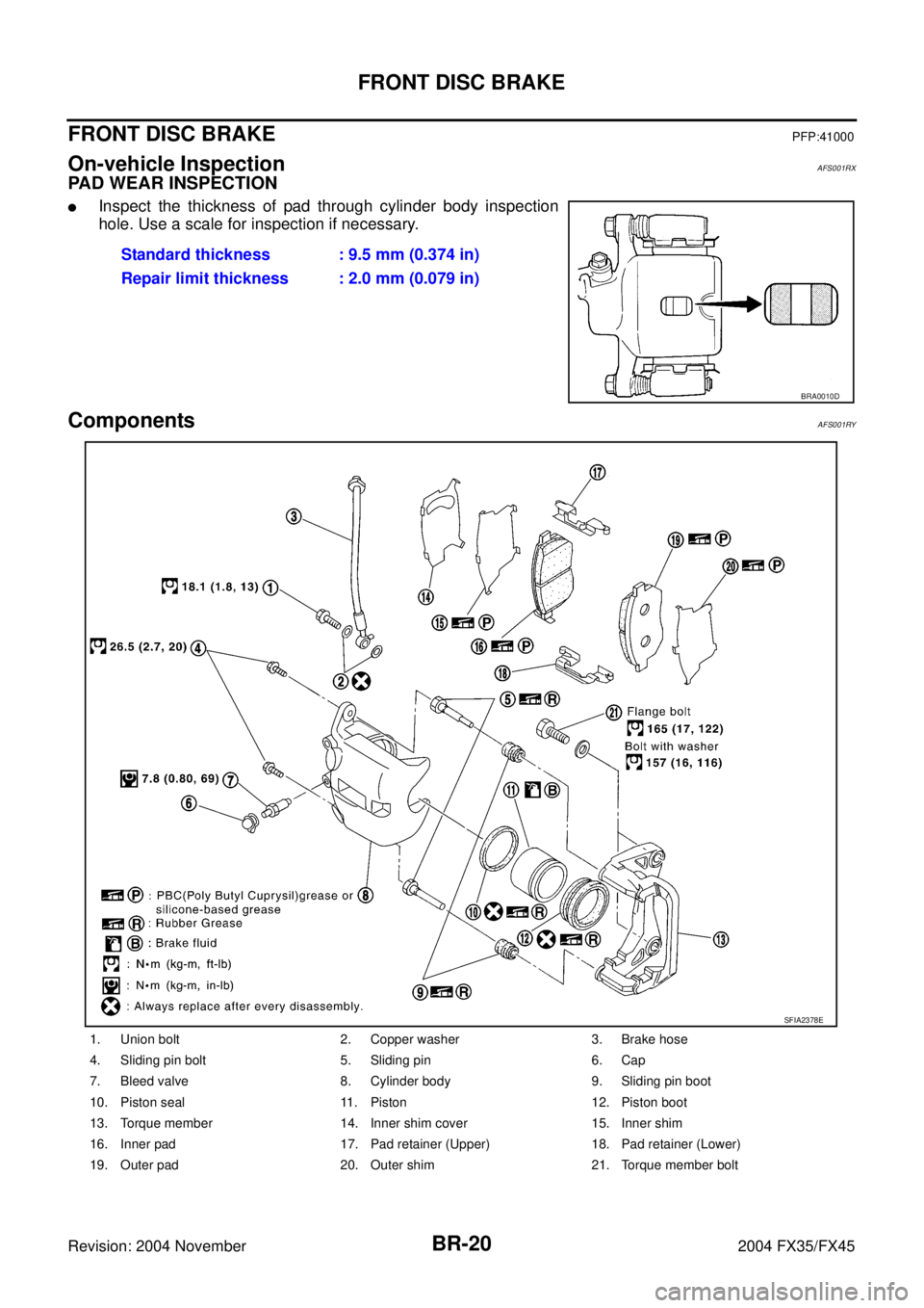
FRONT DISC BRAKEPFP:41000
On-vehicle InspectionAFS001RX
PAD WEAR INSPECTION
�Inspect the thickness of pad through cylinder body inspection
hole. Use a scale for inspection if necessary.
ComponentsAFS001RY
Standard thickness : 9.5 mm (0.374 in)
Repair limit thickness : 2.0 mm (0.079 in)
BRA0010D
1. Union bolt 2. Copper washer 3. Brake hose
4. Sliding pin bolt 5. Sliding pin 6. Cap
7. Bleed valve 8. Cylinder body 9. Sliding pin boot
10. Piston seal 11. Piston 12. Piston boot
13. Torque member 14. Inner shim cover 15. Inner shim
16. Inner pad 17. Pad retainer (Upper) 18. Pad retainer (Lower)
19. Outer pad 20. Outer shim 21. Torque member bolt
SFIA2378E
Page 1114 of 4449

FRONT DISC BRAKE
BR-21
C
D
E
G
H
I
J
K
L
MA
B
BR
Revision: 2004 November 2004 FX35/FX45
WARNING:
Clean dust on caliper and brake pad with a vacuum dust collector to minimize the hazard of airborne
particles or other materials.
CAUTION:
�While removing cylinder body never depress brake pedal because piston will pop out.
�It is not necessary to remove bolts on torque member and brake hose except for disassembly or
replacement of caliper assembly. In this case, hang cylinder body with a wire so as not to stretch
brake hose.
�Do not damage piston boot.
�If any shim is subject to serious corrosion, replace it with a new one.
�Always replace shims and shim covers as a set when replacing brake pads.
�Burnish brake contact surface after refinishing or replacing rotors, after replacing pads, or it a soft
pedal occurs at very low mileage. Refer to BR-24, "
BRAKE BURNISHING PROCEDURE" .
Removal and Installation of Brake PadAFS001RZ
REMOVAL
1. Remove tires from vehicle with power tool.
2. Remove lower sliding pin bolt.
3. Suspend cylinder body with a wire and remove pad and shim from torque member.
INSTALLATION
1. Attach inner shim and shim cover to inner pad, and outer shim to outer pad.
2. Push piston in so that pad is firmly installed and mount cylinder body to torque member.
NOTE:
Using a disc brake piston tool (commercial service tool), etc., makes it easier to push in piston.
CAUTION:
By pushing in piston, brake fluid returns to master cylinder reservoir tank. Watch the level of the
surface of reservoir tank.
3. Attach pat retainer to torque member.
CAUTION:
When attaching pad retainer, attach it firmly so that it does
not float up higher than torque member, as shown in the fig-
ure.
4. Install lower sliding pin bolt and tighten it to the specified torque.
5. Check brake for drag.
6. Attach tires to the vehicle.
Removal and Installation of Brake Caliper AssemblyAFS001S0
REMOVAL
1. Remove tires from vehicle with power tool.
2. Drain brake fluid. Refer to BR-9, "
Drain and Refill" .
3. Remove union bolts and torque member bolts, and remove brake caliper assembly from the vehicle.
4. Remove disc rotor.
INSTALLATION
CAUTION:
�Refill with new brake fluid “DOT3”
�Do not reuse drained brake fluid.
1. Install disc rotor.
PFIA0273E
Page 1115 of 4449

BR-22
FRONT DISC BRAKE
Revision: 2004 November 2004 FX35/FX45
2. Install caliper assembly to the vehicle, and tighten bolts to the
specified torque.
CAUTION:
When attaching caliper assembly to the vehicle, wipe any
oil off knuckle spindle, washers and caliper assembly
attachment surfaces.
3. Install brake hose to brake caliper assembly, and tighten union
bolt to the specified torque.
CAUTION:
�Do not reuse copper washers for union bolt.
�Attach brake hose to caliper assembly together with
union bolt and washers.
4. Refill new brake fluid and bleed air. Refer to BR-10, "
Bleeding Brake System" .
5. Attach tires to the vehicle.
Disassembly and Assembly of Brake Caliper AssemblyAFS001S1
DISASSEMBLY
1. Remove sliding pin bolt, and then remove the pad, shim, shim cover, and pad retainer from the torque
member.
2. Remove sliding pins and sliding pin boots from torque member.
3. Place a wooden block as shown in the figure, and blow air from
union bolt mounting hole to remove pistons and piston boots.
CAUTION:
Do not get your fingers caught in piston.
4. Using a flat-bladed screwdriver, remove piston seal from cylin-
der body.
CAUTION:
Be careful not to damage cylinder inner wall.
SFIA1205E
SFIA1204E
MAA0272D
SFIA1301E
Page 1116 of 4449

FRONT DISC BRAKE
BR-23
C
D
E
G
H
I
J
K
L
MA
B
BR
Revision: 2004 November 2004 FX35/FX45
CALIPER INSPECTION
Cylinder Body
CAUTION:
�Use new brake fluid for cleaning. Do not use mineral oils such as gasoline or kerosene.
�Check inside surface of cylinder for score, rust, wear, damage or foreign materials. If any of the
above conditions are observed, replace cylinder body.
�Minor damage from rust or foreign materials may be eliminated by polishing surface with a fine
emery paper. Replace cylinder body if necessary.
To r q u e M e m b e r
Check for wear, cracks, and damage. If damage or deformation is present, replace the affected part.
Piston
Check piston for score, rust, wear, damage or presence of foreign materials. Replace if any of the above con-
dition are observed.
CAUTION:
Piston sliding surface is plated, do not polish with emery paper even if rust of foreign materials are
stuck to sliding surface.
Sliding Pins, and Sliding Pin Boots
Check sliding pin and sliding pin boot for wear, damage, and cracks. If damage or deformation is present,
replace the affected part.
ASSEMBLY
CAUTION:
Do not use NISSAN Rubber Grease (KRE00 00010, KRE00 00010 01) when assembling.
1. Apply rubber grease to new piston seal and insert seal in to
groove on cylinder body.
CAUTION:
Do not reuse piston seal.
2. Apply brake fluid to piston, rubber grease to piston boot, then
install piston boot in to piston groove.
CAUTION:
Do not reuse piston boot.
3. Insert into cylinder body by hand and insert piston boot piston-side lip into piston groove.
CAUTION:
Press piston evenly and vary the pressing point to prevent cylinder inner wall from being rubbed.
4. Install sliding pins and sliding pin boots to torque member.
5. Attach inner shim and inner shim cover to inner pad, and attach the outer shim to the outer pad.
6. Install cylinder body. Tighten sliding pin bolt to the specified torque.
SFIA1303E
SFIA1305E

 satisfies the speci")