Page 442 of 4449

PRECAUTIONS
ATC-13
C
D
E
F
G
H
I
K
L
MA
B
AT C
Revision: 2004 November 2004 FX35/FX45
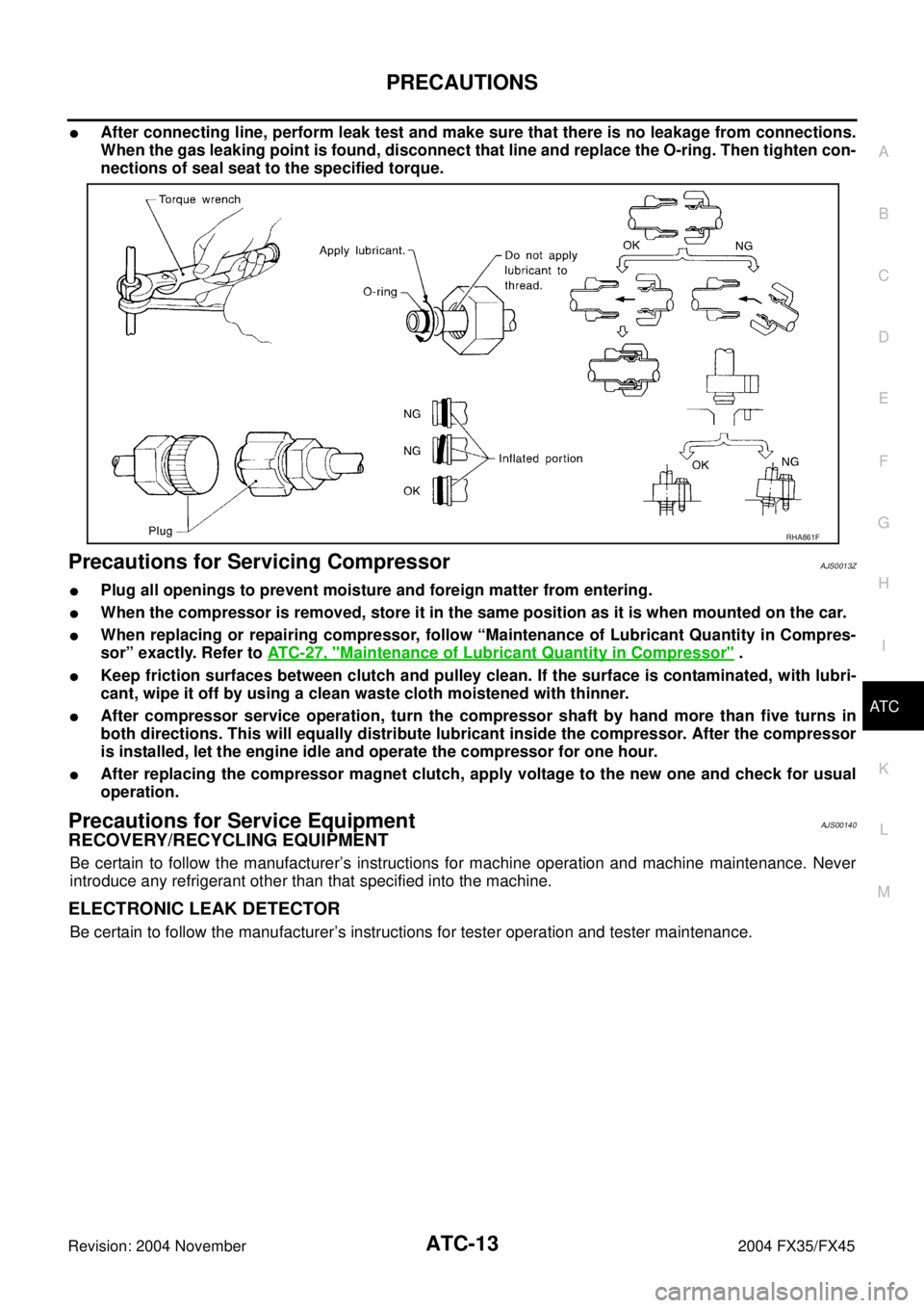
�After connecting line, perform leak test and make sure that there is no leakage from connections.
When the gas leaking point is found, disconnect that line and replace the O-ring. Then tighten con-
nections of seal seat to the specified torque.
Precautions for Servicing CompressorAJS0013Z
�Plug all openings to prevent moisture and foreign matter from entering.
�When the compressor is removed, store it in the same position as it is when mounted on the car.
�When replacing or repairing compressor, follow “Maintenance of Lubricant Quantity in Compres-
sor” exactly. Refer to AT C - 2 7 , "
Maintenance of Lubricant Quantity in Compressor" .
�Keep friction surfaces between clutch and pulley clean. If the surface is contaminated, with lubri-
cant, wipe it off by using a clean waste cloth moistened with thinner.
�After compressor service operation, turn the compressor shaft by hand more than five turns in
both directions. This will equally distribute lubricant inside the compressor. After the compressor
is installed, let the engine idle and operate the compressor for one hour.
�After replacing the compressor magnet clutch, apply voltage to the new one and check for usual
operation.
Precautions for Service EquipmentAJS00140
RECOVERY/RECYCLING EQUIPMENT
Be certain to follow the manufacturer’s instructions for machine operation and machine maintenance. Never
introduce any refrigerant other than that specified into the machine.
ELECTRONIC LEAK DETECTOR
Be certain to follow the manufacturer’s instructions for tester operation and tester maintenance.
RHA861F
Page 556 of 4449

HEATER & COOLING UNIT ASSEMBLY
ATC-127
C
D
E
F
G
H
I
K
L
MA
B
AT C
Revision: 2004 November 2004 FX35/FX45
12. Remove mounting bolts from heater & cooling unit.
13. Disconnect drain hose.
14. Remove ventilator ducts, defroster nozzle and ducts.
15. Remove steering member mounting bolts, nut and harness clips.
16. Remove the steering member, and then remove heater & cooling unit.
INSTALLATION
Installation is basically the reverse order of removal.
CAUTION:
�Replace O-rings for A/C piping with new one, then apply compressor oil to it when installing it.
�Connection point for female-side piping is thin. So, when inserting male-side piping, take care not
to deform female-side piping. Slowly insert in axial direction.
�Insert one-touch joint connection point securely until it clicks.
�After piping has been connected, pull male-side piping by hand to make sure piping does not
come off.
�When recharging refrigerant, check for leaks.
NOTE:
�When filling radiator with coolant, refer to CO-11, "Changing Engine Coolant" (VQ35DE) or CO-36,
"Changing Engine Coolant" (VK45DE).
�Recharge the refrigerant.
RJIA2044E
RJIA2043E
Heater & cooling unit mounting bolt
Tightening torque : 6.8 N·m (0.69 kg-m, 60 in - lb)
Steering member mounting nut and bolt
Tightening torque : 12 N·m (1.2 kg-m, 9 ft - lb)
Page 574 of 4449
REFRIGERANT LINES
ATC-145
C
D
E
F
G
H
I
K
L
MA
B
AT C
Revision: 2004 November 2004 FX35/FX45
INSTALLATION
1. Install the field coil.
Be sure to align the coil′s pin with the hole in the compressor′s
front head.
2. Install the field coil harness clip using a screwdriver.
3. Install the pulley assembly using the installer and a hand press,
and then install the snap ring using snap ring pliers.
4. Install the clutch disc on the drive shaft, together with the original
shim(s). Press the clutch disc down by hand.
5. Using the holder to prevent clutch disc rotation, tighten the bolt
to 14 N·m (1.4 kg-m, 10 ft-lb) torque.
After tightening the bolt, make sure the pulley rotates smoothly.
RHA142E
RHA143EA
RHA127F
RHA086E
Page 575 of 4449
ATC-146
REFRIGERANT LINES
Revision: 2004 November 2004 FX35/FX45
6. Check clearance around the entire periphery of clutch disc.
If the specified clearance is not obtained, replace adjusting
spacer and readjust.
Break-in Operation
When replacing compressor clutch assembly, always carry out the break-in operation. This is done by engag-
ing and disengaging the clutch about thirty times. Break-in operation raises the level of transmitted torque.Disc to pulley clear-
ance: 0.25 - 0.6 mm (0.010 - 0.024 in)
RJIA0965E
Page 577 of 4449

ATC-148
REFRIGERANT LINES
Revision: 2004 November 2004 FX35/FX45
INSTALLATION
Installation is basically the reverse order of removal.
CAUTION:
�Replace O-rings for A/C piping with new one, then apply compressor oil to it when installing it.
�Connection point for female-side piping is thin. So, when inserting male-side piping, take care not
to deform female-side piping. Slowly insert in axial direction.
�Insert one-touch joint connection point securely until it clicks.
�After piping has been connected, pull male-side piping by hand to make sure piping does not
come off.
�When recharging refrigerant, check for leaks.
Removal and Installation of High-pressure Flexible HoseAJS0015U
REMOVAL
1. Use a refrigerant collecting equipment (for HFC-134a) to discharge the refrigerant.
2. Remove the air cleaner and air duct. Refer to EM-17, "
AIR CLEANER AND AIR DUCT" (VQ35DE) or EM-
172, "AIR CLEANER AND AIR DUCT" (VK45DE).
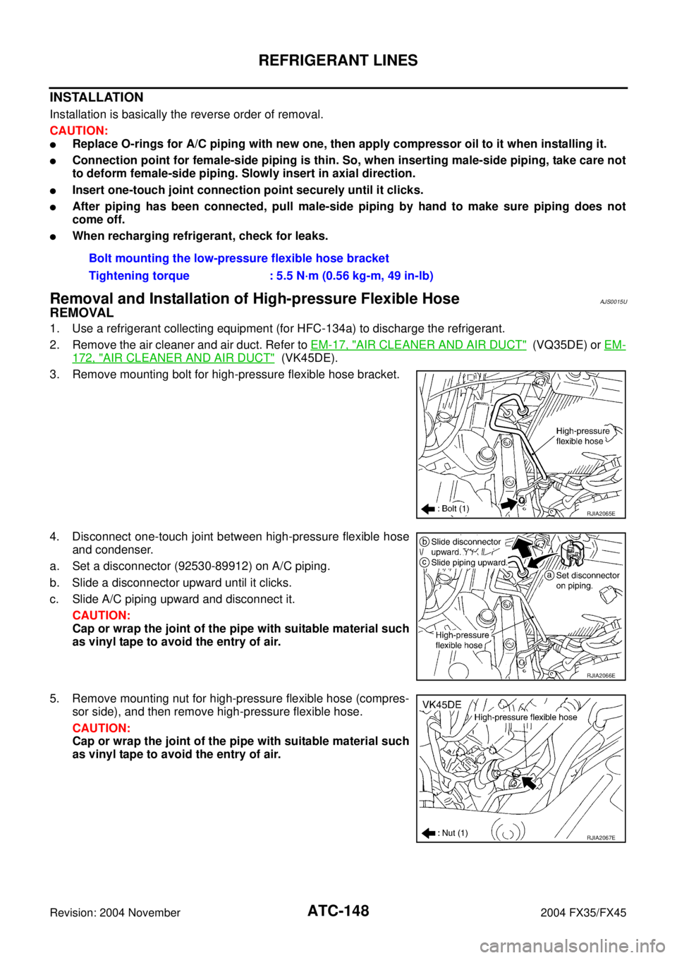
3. Remove mounting bolt for high-pressure flexible hose bracket.
4. Disconnect one-touch joint between high-pressure flexible hose
and condenser.
a. Set a disconnector (92530-89912) on A/C piping.
b. Slide a disconnector upward until it clicks.
c. Slide A/C piping upward and disconnect it.
CAUTION:
Cap or wrap the joint of the pipe with suitable material such
as vinyl tape to avoid the entry of air.
5. Remove mounting nut for high-pressure flexible hose (compres-
sor side), and then remove high-pressure flexible hose.
CAUTION:
Cap or wrap the joint of the pipe with suitable material such
as vinyl tape to avoid the entry of air. Bolt mounting the low-pressure flexible hose bracket
Tightening torque : 5.5 N·m (0.56 kg-m, 49 in-lb)
RJIA2065E
RJIA2066E
RJIA2067E
Page 578 of 4449

REFRIGERANT LINES
ATC-149
C
D
E
F
G
H
I
K
L
MA
B
AT C
Revision: 2004 November 2004 FX35/FX45
INSTALLATION
Installation is basically the reverse order of removal.
CAUTION:
�Replace the O-ring of the high-pressure flexible hose with a new one, then apply compressor oil to
it when installing it.
�Connection point for female-side piping is thin. So, when inserting male-side piping, take care not
to deform female-side piping. Slowly insert in axial direction.
�Insert one-touch joint connection point securely until it clicks.
�After piping has been connected, pull male-side piping by hand to make sure piping does not
come off.
�When recharging refrigerant, check for leaks.
Removal and Installation of Low-pressure Pipe 1 (Engine Compartment)AJS0015V
REMOVAL
1. Use a refrigerant collecting equipment (for HFC-134a) to discharge the refrigerant.
2. Remove cowl top cover. Refer to EI-24, "
COWL TOP" .
3. Remove mounting bolt for low-pressure pipe 1 bracket and low-
pressure flexible hose bracket.
4. Disconnect one-touch joints.
a. Set a disconnector (92530-89916) on A/C piping.
b. Slide a disconnector toward vehicle front until it clicks.
c. Slide A/C piping toward vehicle front and disconnect it.
5. Remove low-pressure pipe 1.
CAUTION:
Cap or wrap the joint of the pipe with suitable material such
as vinyl tape to avoid the entry of air.Bolt mounting the high-pressure flexible hose bracket
Tightening torque : 5.5 N·m (0.56 kg-m, 49 in-lb)
RJIA2068E
RJIA2069E
RJIA2037E
Page 579 of 4449

ATC-150
REFRIGERANT LINES
Revision: 2004 November 2004 FX35/FX45
INSTALLATION
Installation is basically the reverse order of removal.
CAUTION:
�Replace the O-ring of the low-pressure pipe 1 with a new one, then apply compressor oil to it when
installing it.
�Connection point for female-side piping is thin. So, when inserting male-side piping, take care not
to deform female-side piping. Slowly insert in axial direction.
�Insert one-touch joint connection point securely until it clicks.
�After piping has been connected, pull male-side piping by hand to make sure piping does not
come off.
�When recharging refrigerant, check for leaks.
Removal and Installation of High-pressure Pipe 1 and 2 (Engine Compartment)AJS001BH
REMOVAL
1. Use a refrigerant collecting equipment (for HFC-134a) to discharge the refrigerant.
2. Remove low-pressure pipe 1. Refer to ATC-149, "
Removal and Installation of Low-pressure Pipe 1
(Engine Compartment)" .
3. Remove high-pressure flexible hose and low-pressure flexible hose. Refer to ATC-148, "
Removal and
Installation of High-pressure Flexible Hose" and ATC-147, "Removal and Installation of Low-pressure
Flexible Hose" .
4. Remove high-pressure pipe 1 and 2 from clips.
5. Disconnect one-touch joint between condenser and high-pres-
sure pipe 1.
a. Set a disconnector (92530-89908) on A/C piping.
b. Slide a disconnector upward until it clicks.
c. Slide A/C piping upward and disconnect it.
CAUTION:
Cap or wrap the joint of the pipe with suitable material such
as vinyl tape to avoid the entry of air. Bolts mounting the low-pressure pipe 1 bracket and low-pressure flexible hose bracket
Tightening torque : 5.5 N·m (0.56 kg-m, 49 in-lb)
RJIA2070E
RJIA2071E
Page 582 of 4449

REFRIGERANT LINES
ATC-153
C
D
E
F
G
H
I
K
L
MA
B
AT C
Revision: 2004 November 2004 FX35/FX45
Removal and Installation of Liquid TankAJS0015Y
REMOVAL
1. Use a refrigerant collecting equipment (for HFC-134a) to discharge the refrigerant.
2. Remove front grille. Refer to EI-23, "
FRONT GRILLE" .
3. Clean liquid tank and its surrounding area, and remove dirt and rust from tank.
CAUTION:
Be sure to clean carefully.
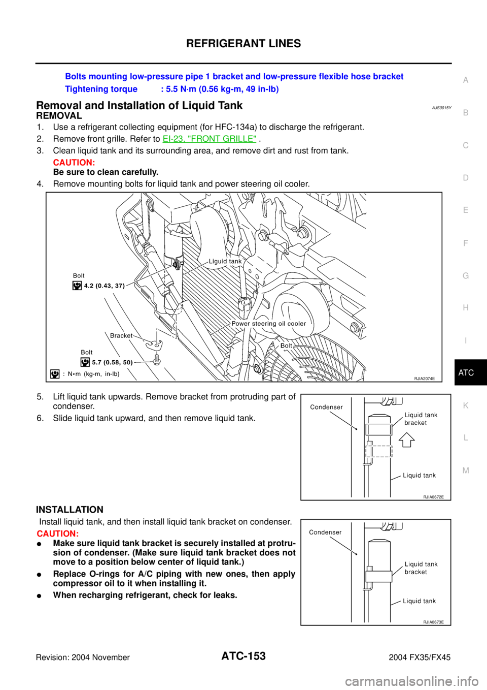
4. Remove mounting bolts for liquid tank and power steering oil cooler.
5. Lift liquid tank upwards. Remove bracket from protruding part of
condenser.
6. Slide liquid tank upward, and then remove liquid tank.
INSTALLATION
Install liquid tank, and then install liquid tank bracket on condenser.
CAUTION:
�Make sure liquid tank bracket is securely installed at protru-
sion of condenser. (Make sure liquid tank bracket does not
move to a position below center of liquid tank.)
�Replace O-rings for A/C piping with new ones, then apply
compressor oil to it when installing it.
�When recharging refrigerant, check for leaks.Bolts mounting low-pressure pipe 1 bracket and low-pressure flexible hose bracket
Tightening torque : 5.5 N·m (0.56 kg-m, 49 in-lb)
RJIA2074E
RJIA0672E
RJIA0673E