Page 1280 of 4449
COMPASS
DI-37
C
D
E
F
G
H
I
J
L
MA
B
DI
Revision: 2004 November 2004 FX35/FX45
Wiring Diagram – COMPAS –AKS007AP
TKWM0683E
Page 1283 of 4449
DI-40
WARNING LAMPS
Revision: 2004 November 2004 FX35/FX45
Wiring Diagram — WARN —AKS005NE
TKWM1054E
Page 1294 of 4449
A/T INDICATOR
DI-51
C
D
E
F
G
H
I
J
L
MA
B
DI
Revision: 2004 November 2004 FX35/FX45
A/T INDICATORPFP:24814
Wiring Diagram — AT/IND —AKS005NI
TKWM1282E
Page 1302 of 4449
WARNING CHIME
DI-59
C
D
E
F
G
H
I
J
L
MA
B
DI
Revision: 2004 November 2004 FX35/FX45
Wiring Diagram — CHIME —AKS005NN
TKWM0813E
Page 1308 of 4449

WARNING CHIME
DI-65
C
D
E
F
G
H
I
J
L
MA
B
DI
Revision: 2004 November 2004 FX35/FX45
Preliminary CheckAKS005NS
CHECK POWER SUPPLY AND GROUND CIRCUIT
1. CHECK FUSE AND FUSIBLE LINK
Check BCM fuses and fusible link for blown-out.
Refer to DI-59, "Wiring Diagram — CHIME —" .
OK or NG
OK >> GO TO 2.
NG >> If fuse or fusible link is blown, be sure to eliminate cause of malfunction before installing new fuse
or fusible link. Refer to PG-3, "
POWER SUPPLY ROUTING CIRCUIT" .
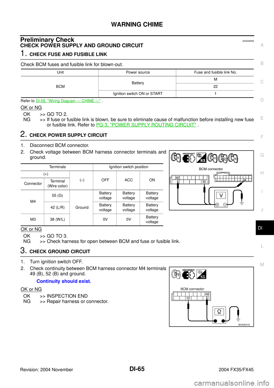
2. CHECK POWER SUPPLY CIRCUIT
1. Disconnect BCM connector.
2. Check voltage between BCM harness connector terminals and
ground.
OK or NG
OK >> GO TO 3.
NG >> Check harness for open between BCM and fuse or fusible link.
3. CHECK GROUND CIRCUIT
1. Turn ignition switch OFF.
2. Check continuity between BCM harness connector M4 terminals
49 (B), 52 (B) and ground.
OK or NG
OK >> INSPECTION END
NG >> Repair harness or connector.
Unit Power source Fuse and fusible link No.
BCMBatteryM
22
Ignition switch ON or START 1
Terminals Ignition switch position
(+)
(–) OFF ACC ON
ConnectorTerminal
(Wire color)
M455 (G)
GroundBattery
voltageBattery
voltageBattery
voltage
42 (L/R)Battery
voltageBattery
voltageBattery
voltage
M3 38 (W/L) 0V 0VBattery
voltage
Continuity should exist.
SKIA5041E
Page 1315 of 4449

DI-72
WARNING CHIME
Revision: 2004 November 2004 FX35/FX45
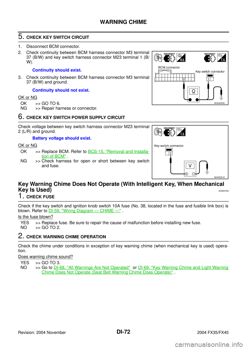
5. CHECK KEY SWITCH CIRCUIT
1. Disconnect BCM connector.
2. Check continuity between BCM harness connector M3 terminal
37 (B/W) and key switch harness connector M23 terminal 1 (B/
W).
3. Check continuity between BCM harness connector M3 terminal
37 (B/W) and ground.
OK or NG
OK >> GO TO 6.
NG >> Repair harness or connector.
6. CHECK KEY SWITCH POWER SUPPLY CIRCUIT
Check voltage between key switch harness connector M23 terminal
2 (L/R) and ground.
OK or NG
OK >> Replace BCM. Refer to BCS-15, "Removal and Installa-
tion of BCM" .
NG >> Check harness for open or short between key switch
and fuse.
Key Warning Chime Does Not Operate (With Intelligent Key, When Mechanical
Key Is Used)
AKS0079U
1. CHECK FUSE
Check if the key switch and ignition knob switch 10A fuse (No. 38, located in the fuse and fusible link box) is
blown. Refer to DI-59, "
Wiring Diagram — CHIME —" .
Is the fuse blown?
YES >> Replace fuse. Be sure to repair the cause of malfunction before installing new fuse.
NO >> GO TO 2.
2. CHECK WARNING CHIME OPERATION
Check the chime under conditions in exception of key warning chime (when mechanical key is used) opera-
tion.
Does warning chime sound?
YES >> GO TO 3.
NO >> Go to DI-68, "
All Warnings Are Not Operated" or DI-69, "Key Warning Chime and Light Warning
Chime Does Not Operate (Seat Belt Warning Chime Does Operate)" . Continuity should exist.
Continuity should not exist.
SKIA5050E
Battery voltage should exist.
SKIA5051E
Page 1322 of 4449
CLOCK
DI-79
C
D
E
F
G
H
I
J
L
MA
B
DI
Revision: 2004 November 2004 FX35/FX45
CLOCKPFP:25820
Wiring Diagram — CLOCK —AKS0056I
TKWM0699E
Page 1327 of 4449
DI-84
REAR VIEW MONITOR
Revision: 2004 November 2004 FX35/FX45
Wiring Diagram — R/VIEW —AKS0068G
TKWM0701E