Page 612 of 4449
AUDIO
AV-21
C
D
E
F
G
H
I
J
L
MA
B
AV
Revision: 2004 November 2004 FX35/FX45
Wiring Diagram -AUDIO- / BOSE SystemAKS007X4
TKWH0260E
Page 641 of 4449
AV-50
AUDIO ANTENNA
Revision: 2004 November 2004 FX35/FX45
Wiring Diagram — M/ANT —AKS007WF
TKWM0569E
Page 654 of 4449
INTEGRATED DISPLAY SYSTEM
AV-63
C
D
E
F
G
H
I
J
L
MA
B
AV
Revision: 2004 November 2004 FX35/FX45
Wiring Diagram — INF/D — AKS00BOA
TKWM0580E
Page 660 of 4449
INTEGRATED DISPLAY SYSTEM
AV-69
C
D
E
F
G
H
I
J
L
MA
B
AV
Revision: 2004 November 2004 FX35/FX45
Wiring Diagram — COMM —AKS00BOC
TKWM0592E
Page 698 of 4449
NAVIGATION SYSTEM
AV-107
C
D
E
F
G
H
I
J
L
MA
B
AV
Revision: 2004 November 2004 FX35/FX45
Wiring Diagram —NAVI—AKS007IT
TKWM1289E
Page 707 of 4449
AV-116
NAVIGATION SYSTEM
Revision: 2004 November 2004 FX35/FX45
Wiring Diagram — COMM —AKS007IU
TKWM0586E
Page 724 of 4449

NAVIGATION SYSTEM
AV-133
C
D
E
F
G
H
I
J
L
MA
B
AV
Revision: 2004 November 2004 FX35/FX45
SELF–DIAGNOSIS RESULT
Quick reference table
1. Select a malfunctioning diagnosis No. in the diagnosis result quick reference table.
2. Find estimated malfunctioning system in the diagnosis No. table and perform check by referring to AV-
11 6 , "Wiring Diagram — COMM —" .
3. Turn the ignition switch OFF and perform self-diagnosis again.
*: DCU = Display control unit
CAUTION:
�When A/C and AV switch has a malfunction, you cannot start. Refer to AV- 1 7 1 , "Unable to Oper-
ate All of A/C and AV switch (Unable to start Self-Diagnosis)" .
�When display has a malfunction, you cannot start. Refer to AV- 1 6 7 , "Screen is Not Shown" .
Self-Diagnosis Codes
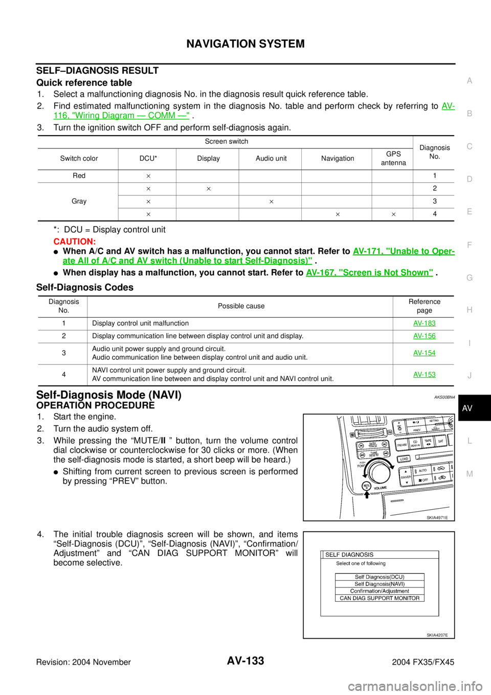
Self-Diagnosis Mode (NAVI)AKS00BN4
OPERATION PROCEDURE
1. Start the engine.
2. Turn the audio system off.
3. While pressing the “MUTE/II ” button, turn the volume control
dial clockwise or counterclockwise for 30 clicks or more. (When
the self-diagnosis mode is started, a short beep will be heard.)
�Shifting from current screen to previous screen is performed
by pressing “PREV” button.
4. The initial trouble diagnosis screen will be shown, and items
“Self-Diagnosis (DCU)”, “Self-Diagnosis (NAVI)”, “Confirmation/
Adjustment” and “CAN DIAG SUPPORT MONITOR” will
become selective.
Screen switch
Diagnosis
No.
Switch color DCU* Display Audio unit NavigationGPS
antenna
Red×1
Gray××2
××3
×××4
Diagnosis
No.Possible causeReference
page
1 Display control unit malfunctionAV-183
2 Display communication line between display control unit and display. AV-156
3Audio unit power supply and ground circuit.
Audio communication line between display control unit and audio unit.AV-154
4NAVI control unit power supply and ground circuit.
AV communication line between and display control unit and NAVI control unit.AV-153
SKIA4971E
SKIA4207E
Page 726 of 4449

NAVIGATION SYSTEM
AV-135
C
D
E
F
G
H
I
J
L
MA
B
AV
Revision: 2004 November 2004 FX35/FX45
SELF–DIAGNOSIS RESULT
Quick Reference Table
1. Select an malfunctioning diagnosis number. in the diagnosis result quick reference table.
2. Find estimated malfunctioning system in the diagnosis number. table and perform check by referring to
AV- 11 6 , "
Wiring Diagram — COMM —" .
3. Turn the ignition switch OFF and perform self-diagnosis again.
*: Navigation = NAVI control unit
CAUTION:
�When A/C and AV switch has a malfunction, you cannot start. Refer to AV- 1 7 1 , "Unable to Operate
All of A/C and AV switch (Unable to start Self-Diagnosis)" .
�When display has a malfunction, you cannot start. Refer to AV- 1 6 7 , "Screen is Not Shown" .
Self-diagnosis Codes
Screen switch
Diagnosis No.
Switch color Navigation* GPS antenna
Red×1
Gray×2
Yellow×3
×4
××5
Diagnosis
No.Possible causeReference
page
1 NAVI control unit malfunctionRefer to
AV-182
2 No map DVD-ROM is inserted in the NAVI control unit.Refer to
AV-158
3When “DVD-ROM error. Please check disc.” is shown.
1. Eject map DVD-ROM and check if it is compatible with the system.
2. Check ejected DVD-ROM for dirt, damage, and warpage.
3. If no error is found, insert a known good map DVD-ROM of the same type and perform self-diagno-
sis again. If same result is shown, the NAVI control unit is malfunctioning. If result is normal, the map
DVD-ROM is malfunctioning.Refer to
AV-158
4If “Error found in DVD-ROM or DVD-ROM driver in control unit. Please perform diagnosis in accor-
dance with service manual” is shown, carry out same inspection as diagnosis No. 3.Refer to
AV-158
5GPS antenna system
1. Visually check for a broken wire in the GPS antenna coaxial cable.
2. Disconnect GPS antenna connector, and make sure approximately 5V is supplied from the NAVI
control unit. If not, the NAVI control unit is malfunctioning. If 5V is supplied, replace the GPS
antenna. If the connection is still malfunction after the replacement of the GPS antenna, the NAVI
control unit is malfunctioning.Refer to
AV-159