Page 107 of 4449

AT-30
A/T CONTROL SYSTEM
Revision: 2004 November 2004 FX35/FX45
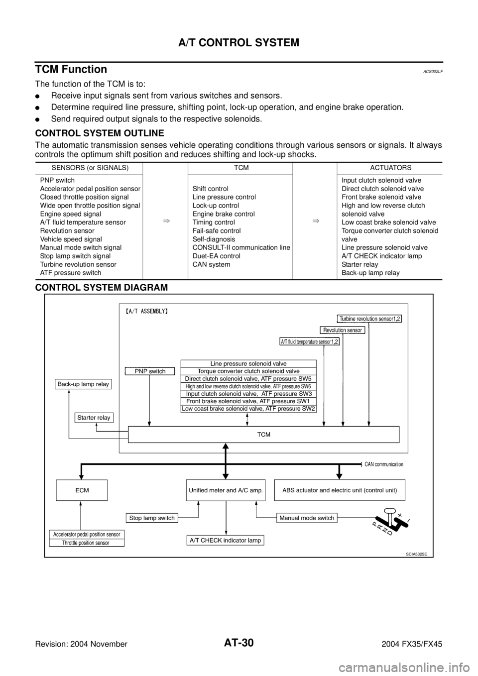
TCM FunctionACS002LF
The function of the TCM is to:
�Receive input signals sent from various switches and sensors.
�Determine required line pressure, shifting point, lock-up operation, and engine brake operation.
�Send required output signals to the respective solenoids.
CONTROL SYSTEM OUTLINE
The automatic transmission senses vehicle operating conditions through various sensors or signals. It always
controls the optimum shift position and reduces shifting and lock-up shocks.
CONTROL SYSTEM DIAGRAM
SENSORS (or SIGNALS)
�TCM
�ACTUATORS
PNP switch
Accelerator pedal position sensor
Closed throttle position signal
Wide open throttle position signal
Engine speed signal
A/T fluid temperature sensor
Revolution sensor
Vehicle speed signal
Manual mode switch signal
Stop lamp switch signal
Turbine revolution sensor
ATF pressure switchShift control
Line pressure control
Lock-up control
Engine brake control
Timing control
Fail-safe control
Self-diagnosis
CONSULT-II communication line
Duet-EA control
CAN systemInput clutch solenoid valve
Direct clutch solenoid valve
Front brake solenoid valve
High and low reverse clutch
solenoid valve
Low coast brake solenoid valve
Torque converter clutch solenoid
valve
Line pressure solenoid valve
A/T CHECK indicator lamp
Starter relay
Back-up lamp relay
SCIA5325E
Page 111 of 4449

AT-34
A/T CONTROL SYSTEM
Revision: 2004 November 2004 FX35/FX45
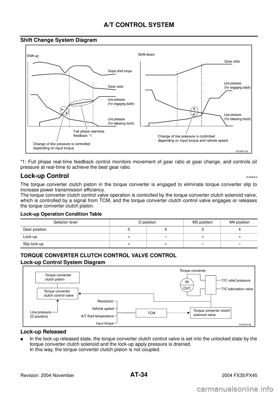
Shift Change System Diagram
*1: Full phase real-time feedback control monitors movement of gear ratio at gear change, and controls oil
pressure at real-time to achieve the best gear ratio.
Lock-up ControlACS002LK
The torque converter clutch piston in the torque converter is engaged to eliminate torque converter slip to
increase power transmission efficiency.
The torque converter clutch control valve operation is controlled by the torque converter clutch solenoid valve,
which is controlled by a signal from TCM, and the torque converter clutch control valve engages or releases
the torque converter clutch piston.
Lock-up Operation Condition Table
TORQUE CONVERTER CLUTCH CONTROL VALVE CONTROL
Lock-up Control System Diagram
Lock-up Released
�In the lock-up released state, the torque converter clutch control valve is set into the unlocked state by the
torque converter clutch solenoid and the lock-up apply pressure is drained.
In this way, the torque converter clutch piston is not coupled.
PCIA0013E
Selector lever D position M5 position M4 position
Gear position 5454
Lock-up×–××
Slip lock-up××––
PCIA0014E
Page 127 of 4449
AT-50
TROUBLE DIAGNOSIS
Revision: 2004 November 2004 FX35/FX45
Circuit DiagramACS007A6
TCWM0245E
Page 183 of 4449
AT-106
DTC U1000 CAN COMMUNICATION LINE
Revision: 2004 November 2004 FX35/FX45
Wiring Diagram — AT — CANACS007AO
TCWM0246E
Page 186 of 4449
DTC P0615 START SIGNAL CIRCUIT
AT-109
D
E
F
G
H
I
J
K
L
MA
B
AT
Revision: 2004 November 2004 FX35/FX45
Wiring Diagram — AT — STSIGACS007AV
TCWM0247E
Page 188 of 4449
DTC P0615 START SIGNAL CIRCUIT
AT-111
D
E
F
G
H
I
J
K
L
MA
B
AT
Revision: 2004 November 2004 FX35/FX45
3. CHECK TERMINAL CORD ASSEMBLY
1. Remove control valve with TCM. Refer to AT- 2 4 2 , "
Control Valve with TCM and A/T Fluid Temperature
Sensor 2" .
2. Disconnect A/T assembly harness connector and control valve with TCM harness connector.
3. Check continuity between A/T assembly harness connector terminal and control valve with TCM harness
connector terminal. Refer to AT- 1 0 9 , "
Wiring Diagram — AT — STSIG" .
4. If OK, check harness for short to ground and short to power.
OK or NG
OK >> Replace the control valve with TCM. Refer to AT- 2 4 2 , "Control Valve with TCM and A/T Fluid Tem-
perature Sensor 2" .
NG >> Replace open circuit or short to ground and short to power in harness or connectors.
4. CHECK DTC
Perform “DTC Confirmation Procedure”.
�Refer to AT- 1 0 8 , "DTC Confirmation Procedure" .
OK or NG
OK >>INSPECTION END
NG >> GO TO 2.
Page 190 of 4449
DTC P0705 PARK/NEUTRAL POSITION SWITCH
AT-113
D
E
F
G
H
I
J
K
L
MA
B
AT
Revision: 2004 November 2004 FX35/FX45
Wiring Diagram — AT — PNP/SWACS007B2
TCWM0248E
Page 191 of 4449

AT-114
DTC P0705 PARK/NEUTRAL POSITION SWITCH
Revision: 2004 November 2004 FX35/FX45
Diagnostic ProcedureACS007B3
1. CHECK PNP SW CIRCUIT
With CONSULT-II
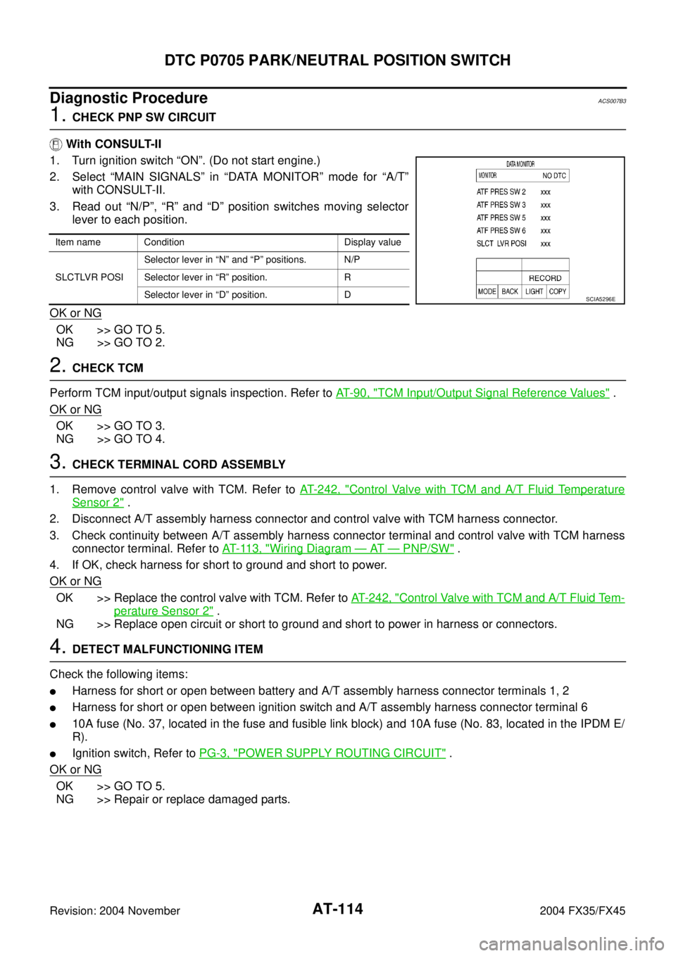
1. Turn ignition switch “ON”. (Do not start engine.)
2. Select “MAIN SIGNALS” in “DATA MONITOR” mode for “A/T”
with CONSULT-II.
3. Read out “N/P”, “R” and “D” position switches moving selector
lever to each position.
OK or NG
OK >> GO TO 5.
NG >> GO TO 2.
2. CHECK TCM
Perform TCM input/output signals inspection. Refer to AT- 9 0 , "
TCM Input/Output Signal Reference Values" .
OK or NG
OK >> GO TO 3.
NG >> GO TO 4.
3. CHECK TERMINAL CORD ASSEMBLY
1. Remove control valve with TCM. Refer to AT- 2 4 2 , "
Control Valve with TCM and A/T Fluid Temperature
Sensor 2" .
2. Disconnect A/T assembly harness connector and control valve with TCM harness connector.
3. Check continuity between A/T assembly harness connector terminal and control valve with TCM harness
connector terminal. Refer to AT- 11 3 , "
Wiring Diagram — AT — PNP/SW" .
4. If OK, check harness for short to ground and short to power.
OK or NG
OK >> Replace the control valve with TCM. Refer to AT- 2 4 2 , "Control Valve with TCM and A/T Fluid Tem-
perature Sensor 2" .
NG >> Replace open circuit or short to ground and short to power in harness or connectors.
4. DETECT MALFUNCTIONING ITEM
Check the following items:
�Harness for short or open between battery and A/T assembly harness connector terminals 1, 2
�Harness for short or open between ignition switch and A/T assembly harness connector terminal 6
�10A fuse (No. 37, located in the fuse and fusible link block) and 10A fuse (No. 83, located in the IPDM E/
R).
�Ignition switch, Refer to PG-3, "POWER SUPPLY ROUTING CIRCUIT" .
OK or NG
OK >> GO TO 5.
NG >> Repair or replace damaged parts.
Item name Condition Display value
SLCTLVR POSISelector lever in “N” and “P” positions. N/P
Selector lever in “R” position. R
Selector lever in “D” position. D
SCIA5296E