BRC-1
BRAKE CONTROL SYSTEM
F BRAKES
CONTENTS
C
D
E
G
H
I
J
K
L
M
SECTION BRC
A
B
BRC
Revision: 2004 November 2004 FX35/FX45
BRAKE CONTROL SYSTEM
VDC/TCS/ABS
PRECAUTIONS .......................................................... 3
Precautions for Supplemental Restraint System
(SRS) “AIR BAG” and “SEAT BELT PRE-TEN-
SIONER” .................................................................. 3
Precautions for Brake System .................................. 3
Precautions for Brake Control .................................. 3
PREPARATION ........................................................... 5
Special Service Tools ............................................... 5
Commercial Service Tools ........................................ 5
ON-VEHICLE SERVICE ............................................. 6
Adjustment of Steering Angle Sensor Neutral Posi-
tion ........................................................................... 6
Calibration of Decel G-sensor (AWD Model) ............ 6
SYSTEM DESCRIPTION ............................................ 8
System Diagram ....................................................... 8
VDC Function ........................................................... 8
TCS Function ........................................................... 8
ABS Function ........................................................... 8
EBD Function ........................................................... 9
Fail-Safe Function .................................................... 9
VDC / TCS SYSTEM ............................................. 9
ABS, EBD SYSTEM .............................................. 9
Hydraulic Circuit Diagram ...................................... 10
CAN COMMUNICATION ...........................................11
System Description ................................................. 11
TROUBLE DIAGNOSIS ............................................ 12
How to Proceed With Diagnosis ............................. 12
BASIC CONCEPT ............................................... 12
DIAGNOSIS FLOWCHART ................................ 13
ASKING COMPLAINTS ...................................... 14
EXAMPLE OF DIAGNOSIS SHEET ................... 14
Component Installation Location ............................ 15
Schematic .............................................................. 16
Wiring Diagram — VDC — ..................................... 17
Control Unit Input/Output Signal Standard ............. 23
REFERENCE VALUE FROM CONSULT-II ......... 23
CONSULT-II Functions ........................................... 25
CONSULT-II MAIN FUNCTION ........................... 25
CONSULT-II BASIC OPERATION PROCEDURE ... 26
SELF-DIAGNOSIS .............................................. 27
DATA MONITOR ................................................. 30
ACTIVE TEST ..................................................... 33
For Fast and Accurate Diagnosis ........................... 35
PRECAUTIONS FOR DIAGNOSIS ..................... 35
Basic Inspection ..................................................... 36
BASIC INSPECTION 1: BRAKE FLUID
AMOUNT, LEAKS, AND BRAKE PADS INSPEC-
TION .................................................................... 36
BASIC INSPECTION 2: POWER SYSTEM TER-
MINAL LOOSENESS AND BATTERY INSPEC-
TION .................................................................... 36
BASIC INSPECTION 3: ABS WARNING LAMP,
VDC OFF INDICATOR LAMP, SLIP INDICATOR
LAMP AND BRAKE WARNING LAMP INSPEC-
TION .................................................................... 37
Inspection 1: Wheel Sensor System ....................... 37
Inspection 2: Engine System .................................. 39
Inspection 3: VDC/TCS/ABS Control Unit System ... 40
Inspection 4: Pressure Sensor System .................. 40
Inspection 5: Steering Angle Sensor System ......... 42
Inspection 6: Yaw Rate/Side G-Sensor (2WD
model), Yaw Rate/Side/Decel G-sensor (AWD mod-
els) System ............................................................. 44
Inspection 7: Solenoid and VDC Change-Over
Valve System .......................................................... 46
Inspection 8: Actuator Motor System ...................... 47
Inspection 9: ABS Actuator and Electric Unit (Con-
trol Unit) Power Supply and Ground System .......... 48
Inspection 10: Stop Lamp Switch System .............. 50
Inspection 11: Brake Fluid Level Switch System .... 51
Inspection 12: When “ST ANG SEN SIGNAL”
Appears on Self-Diagnosis Results Display ........... 52
Inspection 13: When “DECEL G SEN SET” Appears
on Self-Diagnosis Results Display (AWD Model) ... 52
Inspection 14: CAN Communication System .......... 53
Component Inspection ............................................ 53
VDC OFF SWITCH ............................................. 53
Symptom 1: Excessive ABS Function Operation
BRC-8
[VDC/TCS/ABS]
SYSTEM DESCRIPTION
Revision: 2004 November 2004 FX35/FX45
SYSTEM DESCRIPTIONPFP:00000
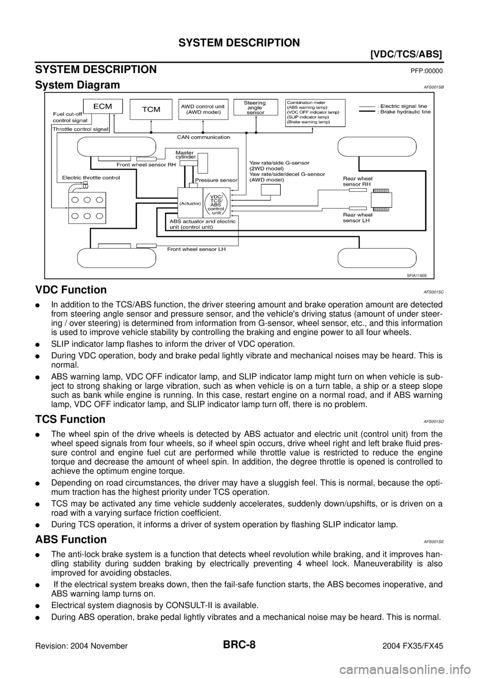
System DiagramAFS001SB
VDC FunctionAFS001SC
�In addition to the TCS/ABS function, the driver steering amount and brake operation amount are detected
from steering angle sensor and pressure sensor, and the vehicle's driving status (amount of under steer-
ing / over steering) is determined from information from G-sensor, wheel sensor, etc., and this information
is used to improve vehicle stability by controlling the braking and engine power to all four wheels.
�SLIP indicator lamp flashes to inform the driver of VDC operation.
�During VDC operation, body and brake pedal lightly vibrate and mechanical noises may be heard. This is
normal.
�ABS warning lamp, VDC OFF indicator lamp, and SLIP indicator lamp might turn on when vehicle is sub-
ject to strong shaking or large vibration, such as when vehicle is on a turn table, a ship or a steep slope
such as bank while engine is running. In this case, restart engine on a normal road, and if ABS warning
lamp, VDC OFF indicator lamp, and SLIP indicator lamp turn off, there is no problem.
TCS FunctionAFS001SD
�The wheel spin of the drive wheels is detected by ABS actuator and electric unit (control unit) from the
wheel speed signals from four wheels, so if wheel spin occurs, drive wheel right and left brake fluid pres-
sure control and engine fuel cut are performed while throttle value is restricted to reduce the engine
torque and decrease the amount of wheel spin. In addition, the degree throttle is opened is controlled to
achieve the optimum engine torque.
�Depending on road circumstances, the driver may have a sluggish feel. This is normal, because the opti-
mum traction has the highest priority under TCS operation.
�TCS may be activated any time vehicle suddenly accelerates, suddenly down/upshifts, or is driven on a
road with a varying surface friction coefficient.
�During TCS operation, it informs a driver of system operation by flashing SLIP indicator lamp.
ABS FunctionAFS001SE
�The anti-lock brake system is a function that detects wheel revolution while braking, and it improves han-
dling stability during sudden braking by electrically preventing 4 wheel lock. Maneuverability is also
improved for avoiding obstacles.
� If the electrical system breaks down, then the fail-safe function starts, the ABS becomes inoperative, and
ABS warning lamp turns on.
�Electrical system diagnosis by CONSULT-II is available.
�During ABS operation, brake pedal lightly vibrates and a mechanical noise may be heard. This is normal.
SFIA1160E


 SYSTEM
BL-187
C
D
E
F
G
H
J
K
L
MA
B
BL
Revision: 2004 November 2004 FX35/FX45
Wiring Diagram -VEHSEC-AIS004OX
TIWM0334E")

BL-209
C
D
E
F
G
H
J
K
L
MA
B
BL
Revision: 2004 November 2004 FX35/FX45
Wiring Diagram – NATS –AIS004PE
MODELS WITH INTELLIGENT KEY SYSTEM
TIWM0422E")