2004 DAEWOO LACETTI Intake air temperature
[x] Cancel search: Intake air temperaturePage 590 of 2643
1F – 344IENGINE CONTROLS
DAEWOO V–121 BL4
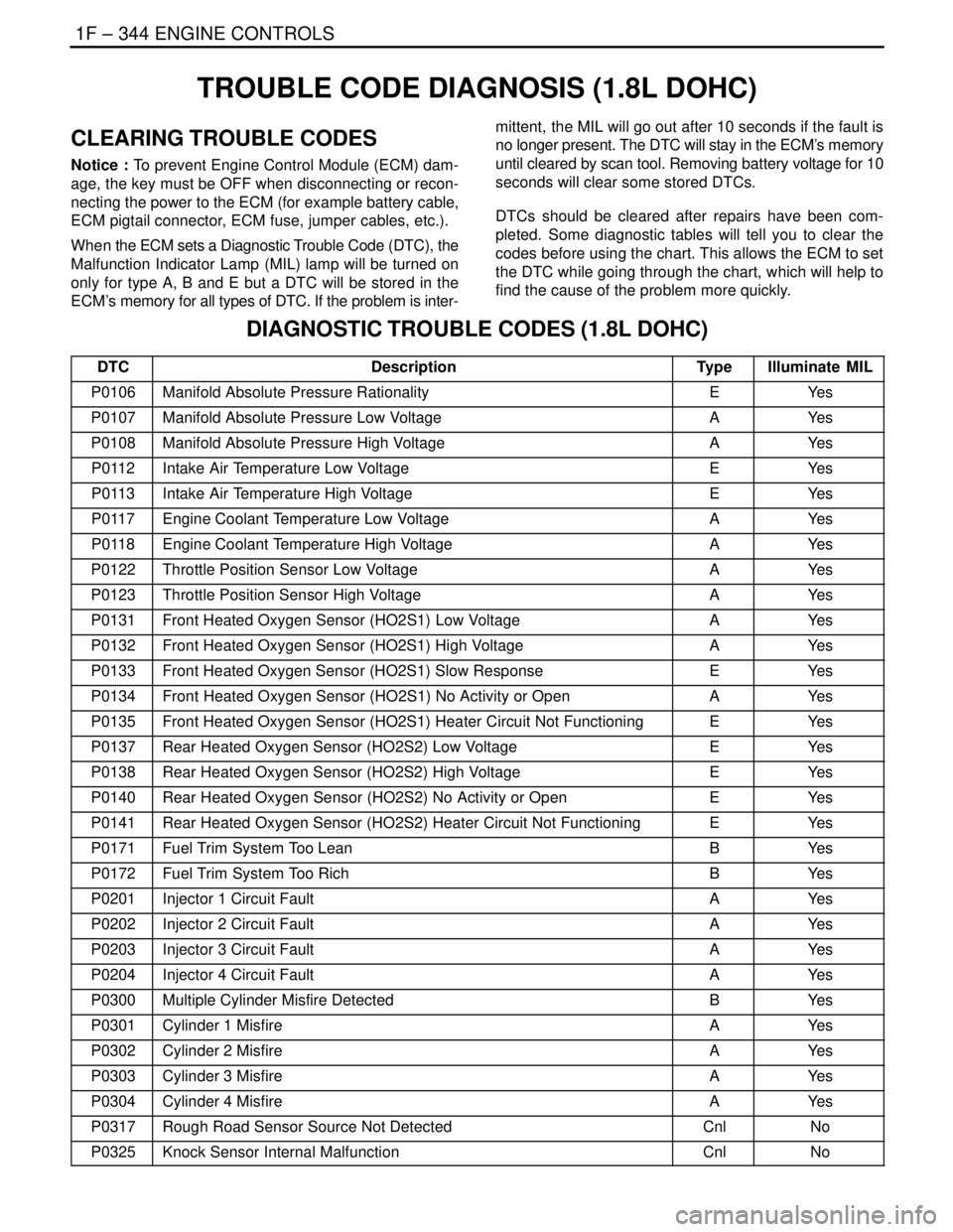
TROUBLE CODE DIAGNOSIS (1.8L DOHC)
CLEARING TROUBLE CODES
Notice : To prevent Engine Control Module (ECM) dam-
age, the key must be OFF when disconnecting or recon-
necting the power to the ECM (for example battery cable,
ECM pigtail connector, ECM fuse, jumper cables, etc.).
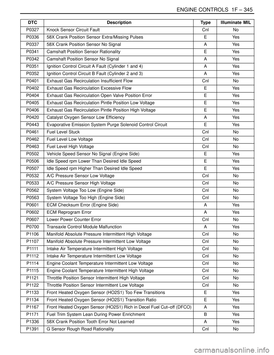
When the ECM sets a Diagnostic Trouble Code (DTC), the
Malfunction Indicator Lamp (MIL) lamp will be turned on
only for type A, B and E but a DTC will be stored in the
ECM’s memory for all types of DTC. If the problem is inter-mittent, the MIL will go out after 10 seconds if the fault is
no longer present. The DTC will stay in the ECM’s memory
until cleared by scan tool. Removing battery voltage for 10
seconds will clear some stored DTCs.
DTCs should be cleared after repairs have been com-
pleted. Some diagnostic tables will tell you to clear the
codes before using the chart. This allows the ECM to set
the DTC while going through the chart, which will help to
find the cause of the problem more quickly.
DIAGNOSTIC TROUBLE CODES (1.8L DOHC)
DTCDescriptionTypeIlluminate MIL
P0106Manifold Absolute Pressure RationalityEYe s
P0107Manifold Absolute Pressure Low VoltageAYe s
P0108Manifold Absolute Pressure High VoltageAYe s
P0112Intake Air Temperature Low VoltageEYe s
P0113Intake Air Temperature High VoltageEYe s
P0117Engine Coolant Temperature Low VoltageAYe s
P0118Engine Coolant Temperature High VoltageAYe s
P0122Throttle Position Sensor Low VoltageAYe s
P0123Throttle Position Sensor High VoltageAYe s
P0131Front Heated Oxygen Sensor (HO2S1) Low VoltageAYe s
P0132Front Heated Oxygen Sensor (HO2S1) High VoltageAYe s
P0133Front Heated Oxygen Sensor (HO2S1) Slow ResponseEYe s
P0134Front Heated Oxygen Sensor (HO2S1) No Activity or OpenAYe s
P0135Front Heated Oxygen Sensor (HO2S1) Heater Circuit Not FunctioningEYe s
P0137Rear Heated Oxygen Sensor (HO2S2) Low VoltageEYe s
P0138Rear Heated Oxygen Sensor (HO2S2) High VoltageEYe s
P0140Rear Heated Oxygen Sensor (HO2S2) No Activity or OpenEYe s
P0141Rear Heated Oxygen Sensor (HO2S2) Heater Circuit Not FunctioningEYe s
P0171Fuel Trim System Too LeanBYe s
P0172Fuel Trim System Too RichBYe s
P0201Injector 1 Circuit FaultAYe s
P0202Injector 2 Circuit FaultAYe s
P0203Injector 3 Circuit FaultAYe s
P0204Injector 4 Circuit FaultAYe s
P0300Multiple Cylinder Misfire DetectedBYe s
P0301Cylinder 1 MisfireAYe s
P0302Cylinder 2 MisfireAYe s
P0303Cylinder 3 MisfireAYe s
P0304Cylinder 4 MisfireAYe s
P0317Rough Road Sensor Source Not DetectedCnlNo
P0325Knock Sensor Internal MalfunctionCnlNo
Page 591 of 2643
ENGINE CONTROLS 1F – 345
DAEWOO V–121 BL4
DTCIlluminate MIL Type Description
P0327Knock Sensor Circuit FaultCnlNo
P033658X Crank Position Sensor Extra/Missing PulsesEYe s
P033758X Crank Position Sensor No SignalAYe s
P0341Camshaft Position Sensor RationalityEYe s
P0342Camshaft Position Sensor No SignalAYe s
P0351Ignition Control Circuit A Fault (Cylinder 1 and 4)AYe s
P0352Ignition Control Circuit B Fault (Cylinder 2 and 3)AYe s
P0401Exhaust Gas Recirculation Insufficient FlowCnlNo
P0402Exhaust Gas Recirculation Excessive FlowEYe s
P0404Exhaust Gas Recirculation Open Valve Position ErrorEYe s
P0405Exhaust Gas Recirculation Pintle Position Low VoltageEYe s
P0406Exhaust Gas Recirculation Pintle Position High VoltageEYe s
P0420Catalyst Oxygen Sensor Low EfficiencyAYe s
P0443Evaporative Emission System Purge Solenoid Control CircuitEYe s
P0461Fuel Level StuckCnlNo
P0462Fuel Level Low VoltageCnlNo
P0463Fuel Level High VoltageCnlNo
P0502Vehicle Speed Sensor No Signal (Engine Side)EYe s
P0506Idle Speed rpm Lower Than Desired Idle SpeedEYe s
P0507Idle Speed rpm Higher Than Desired Idle SpeedEYe s
P0532A/C Pressure Sensor Low VoltageCnlNo
P0533A/C Pressure Sensor High VoltageCnlNo
P0562System Voltage Too Low (Engine Side)CnlNo
P0563System Voltage Too High (Engine Side)CnlNo
P0601ECM Checksum Error (Engine Side)AYe s
P0602ECM Reprogram ErrorAYe s
P0607Lower Power Counter ErrorCnlNo
P0700Transaxle Control Module MalfunctionAYe s
P1106Manifold Absolute Pressure Intermittent High VoltageCnlNo
P1107Manifold Absolute Pressure Intermittent Low VoltageCnlNo
P 1111Intake Air Temperature Intermittent High VoltageCnlNo
P1112Intake Air Temperature Intermittent Low VoltageCnlNo
P1114Engine Coolant Temperature Intermittent Low VoltageCnlNo
P1115Engine Coolant Temperature Intermittent High VoltageCnlNo
P1121Throttle Position Sensor Intermittent High VoltageCnlNo
P1122Throttle Position Sensor Intermittent Low VoltageCnlNo
P1133Front Heated Oxygen Sensor (HO2S1) Too Few TransitionsEYe s
P1134Front Heated Oxygen Sensor (HO2S1) Transition RatioEYe s
P1167Front Heated Oxygen Sensor (HO2S1) Rich in Decel Fuel Cut–off (DFCO)AYe s
P1171Fuel Trim System Lean During Power EnrichmentBYe s
P133658X Crank Position Tooth Error Not LearnedAYe s
P1391G Sensor Rough Road RationalityCnlNo
Page 593 of 2643

ENGINE CONTROLS 1F – 347
DAEWOO V–121 BL4
DIAGNOSTIC TROUBLE CODE (DTC) P0106
MANIFOLD ABSOLUTE PRESSURE RATIONALITY
Circuit Description
The Engine Control Module (ECM) uses the Manifold Ab-
solute Pressure (MAP) sensor to control the fuel delivery
and the ignition timing. The MAP sensor measures the
changes in the intake manifold pressure which results
from engine load (intake manifold vacuum) and the rpm
changes, and it converts these into voltage outputs. The
ECM can detect if the MAP sensor is not responding to the
Throttle Position (TP) changes by comparing the actual
MAP change to a predicted MAP change based on the
amount of TP change that occurs. If the ECM does not see
the expected MAP change or more, DTC P0106 will set.
Conditions for Setting the DTC
S Altitude compensated MAP reading is higher than
high threshold or lower than low threshold table
based on rpm and TP signal.
S DTCs P0107, P0108, P0117, P0118, P0122,
P0123, P0201, P0202, P0203, P0204, P0300,
P0351, P0352, P0402, P0404, P1404, P0405,
P0406, P0506, P0507 are not set.
S Engine running.
S Valid Barometric Pressure (BARO) update.
S Torque Converter Clutch (TCC) steady (A/T).
S A/C steady state.
S No TP sensor fail conditions present.
S No MAP fail conditions present.
S Change in Idle Air Control (IAC) is less than 5%.
S Coolant temperature is greater than –10°C (14°F).
S Change in rpm is less than 200.
S Change in TP sensor is less than 3%.
S Change in Exhaust Gas Recirculation (EGR) value
is less than 6%.
S The rpm is between 1300 and 4500.
S All of the above are stabilized for 1.5 seconds.
Action Taken When the DTC Sets
S The Malfunction Indicator Lamp (MIL) will illuminate
after three consecutive ignition cycle with a fail.
S The ECM will record operating conditions at the
time the diagnostic fails. This information will be
stored in the Freeze Frame and Failure Records
buffers.
S A history DTC is stored.
S The ECM will substitute a fixed MAP value and use
TP sensor to control the fuel delivery. (The scan
tool will not show defaulted value.)
Conditions for Clearing the MIL/DTC
S The MIL will turn off after four consecutive ignition
cycles in which the diagnostic runs without a fault.
S A history DTC will clear after 40 consecutive warm–
up cycles without a fault.
S DTC(s) can be cleared by using the scan tool.
S Disconnecting the ECM battery feed for more than
10 seconds.Diagnostic Aids
With the ignition ON and the engine stopped, the manifold
pressure is equal to atmospheric pressure and the signal
voltage will be high. This information is used by the ECM
as an indication of vehicle altitude. Comparison of this
reading with a known good vehicle with the same sensor
is a good way to check the accuracy of a suspect sensor.
Readings should be the same +0.4 volt.
The MAP sensor vacuum source should be thoroughly
checked for restrictions at the intake manifold.
Test Description
Numbers below refer to the step numbers on the Diagnos-
tic Table.
1. The On–Board Diagnostic (EOBD) System Check
prompts the technician to complete some basic
checks and store the freeze frame and failure re-
cords data on the scan tool if applicable. This
creates an electronic copy of the data taken when
the occurred. The information is then stored on the
scan tool for later reference.
2. A sensor that displays an ignition ON, engine OFF
BARO value that does not appear normal for the
altitude the vehicle is in should be considered to be
malfunctioning.
3. While starting the engine, the MAP sensor should
detect any changes in the manifold pressure. This
test is to determine if the sensor is stuck at a value.
4. A normal MAP sensor will react as quickly to the
throttle changes as they can be made. A sensor
should not appear to be lazy or catch up with the
throttle movements.
5. This step checks if the reason for no MAP change
was due to a faulty sensor or vacuum source to the
sensor.
6. The MAP sensor vacuum source should be thor-
oughly checked for restrictions. A drill bit can be
used to clean out any casting flash that may exist in
the vacuum port.
7. The MAP sensor vacuum source should be thor-
oughly checked for restrictions. A drill bit can be
used to clean out any casting flash that may exist in
the vacuum port.
9. The MAP Sensor System Performance diagnostic
may have to complete several tests before deter-
mining if the diagnostic has passed or failed the last
test. Operate the vehicle in the Conditions for Set-
ting the DTC several times to ensure that the diag-
nostic runs enough tests to pass or fail.
10. If no faults have been found at this point and no
additional DTCs were set, refer to ”Diagnostic
Aids”in this section for additional checks and infor-
mation.
Page 601 of 2643

ENGINE CONTROLS 1F – 355
DAEWOO V–121 BL4
DIAGNOSTIC TROUBLE CODE (DTC) P0112
INTAKE AIR TEMPERATURE LOW VOLTAGE
Circuit Description
The Intake Air Temperature (IAT) sensor uses a thermistor
to control the signal voltage to the Engine Control Module
(ECM). The ECM supplies a 5 volt reference and a ground
to the sensor. When the air is cold, the resistance is high;
therefore the IAT signal voltage will be high. If the intake
air is warm, resistance is low; therefore the IAT signal volt-
age will be low.
Conditions for Setting the DTC
S IAT is less than 149°C (300°F).
S Engine run time is greater than 120 seconds.
S Vehicles speed is greater than or equal to 50 km/h
(31 mph).
S DTC P0502 is not set.
Action Taken When the DTC Sets
S The Malfunction Indicator Lamp (MIL) will illuminate
after three consecutive ignition cycle with a fail.
S The ECM will record operating conditions at the
time the diagnostic fails. This information will be
stored in the Freeze Frame and Failure Records
buffers.
S A history DTC is stored.
S The ECM will substitute a default value for intake
air temperature. The scan tool will not show the
defaulted value.
Conditions for Clearing the MIL/DTC
S The MIL will turn off after four consecutive ignition
cycles in which the diagnostic runs without a fault.S A history DTC will clear after 40 consecutive warm–
up cycles without a fault.
S DTC(s) can be cleared by using the scan tool.
S Disconnecting the ECM battery feed for more than
10 seconds.
Diagnostic Aids
If the vehicle is at ambient temperature, compare the IAT
sensor to the Engine Coolant Temperature (ECT) sensor.
The IAT sensor and the ECT sensor should be relatively
close to each other.
Use the Temperature vs. Resistance Values table to eval-
uate the possibility of a skewed sensor. Refer to ”Temper-
ature vs. Resistance” in this section.
Test Description
Number(s) below refer to the step number(s) on the Diag-
nostic Table.
1. The On–Board Diagnostic (EOBD) System Check
prompts the technician to complete some basic
checks and store the freeze frame and failure re-
cords data on the scan tool if applicable. This
creates an electronic copy of the data taken when
the malfunction occurred. The information is then
stored on the scan tool for later reference.
4. This step simulates a DTC P0113 condition. If the
scan tool displays the specified value, the IAT sig-
nal circuit, the ECM are OK.
8. The replacement ECM must be reprogrammed.
Refer to the latest Techline procedure for ECM re-
programming.
Page 602 of 2643

1F – 356IENGINE CONTROLS
DAEWOO V–121 BL4
DTC P0112 – Intake Air Temperature Low Voltage
StepActionValue(s)YesNo
1Perform an On–Board Diagnostic (EOBD) System
Check.
Was the check performed?–Go to Step 2Go to
”On–Board
Diagnostic Sys-
tem Check”
21. Install a scan tool to the Data Link Connector
(DLC).
2. Turn the ignition ON.
Is the Intake Air Temperature (IAT) value greater
than the specified value?128°C
(262 °F)Go to Step 4Go to Step 3
31. Turn the ignition switch ON with the engine
OFF, review Freeze Frame data, and note the
parameters.
2. Operate the vehicle within the Freeze Frame
conditions and Conditions for Setting The DTC
as noted.
Is the IAT sensor value greater than the specified
value?128°C
(262 °F)Go to Step 4Go to
”Diagnostic
Aids”
41. Turn the ignition switch OFF.
2. Disconnect the IAT sensor electrical connector.
3. Turn the ignition switch ON.
Is the IAT sensor value below the specified value?–30 °C
(–22 °F)Go to Step 5Go to Step 6
5Replace IAT sensor.
Is the repair complete?–Go to Step 10–
6With a test light connected to battery +, probe the
IAT sensor signal circuit, terminal 2 at the IAT sensor
connector.
Does the test light illuminate?–Go to Step 7Go to Step 9
71. Turn the ignition switch OFF.
2. Disconnect the Engine Control Module (ECM)
connector.
3. With a test light connected to B+, probe the
IAT sensor signal circuit, terminal 2 at the IAT
sensor electrical connector.
Does the test light illuminate?–Go to Step 8Go to Step 9
8Repair the short to ground circuit in the IAT sensor
signal circuit as needed.
Is the repair complete?–Go to Step 10–
91. Turn the ignition OFF.
2. Replace the ECM.
Is the action complete?–Go to Step 10–
Page 604 of 2643

1F – 358IENGINE CONTROLS
DAEWOO V–121 BL4
DIAGNOSTIC TROUBLE CODE (DTC) P0113
INTAKE AIR TEMPERATURE HIGH VOLTAGE
Circuit Description
The Intake Air Temperature (IAT) sensor uses a thermistor
to control the signal voltage to the Engine Control Module
(ECM). The ECM supplies a 5 volt reference and a ground
to the sensor. When the air is cold, the resistance is high;
therefore the IAT signal voltage will be high. If the intake
air is warm, resistance is low; therefore the IAT signal volt-
age will be low.
Conditions for Setting the DTC
S IAT is less than –38°C (–36°F).
S Vehicles speed is less than 25 km/h (16 mph).
S Engine run time is greater than 120 seconds.
S Engine Coolant Temperature (ECT) is above 70 °C
158 °F).
S Calculated air are flow is less than 15 g/second.
S DTC P0502, P0117, P0118 not set.
Action Taken When the DTC Sets
S The Malfunction Indicator Lamp (MIL) will illuminate
after three consecutive ignition cycle with a fail.
S The ECM will record operating conditions at the
time the diagnostic fails. This information will be
stored in the Freeze Frame and Failure Records
buffers.
S A history DTC is stored.
S The ECM will substitute a default value for intake
air temperature. The scan tool will not show the
defaulted value.
Conditions for Clearing the MIL/DTC
S The MIL will turn off after four consecutive ignition
cycles in which the diagnostic runs without a fault.S A history DTC will clear after 40 consecutive warm–
up cycles without a fault.
S DTC(s) can be cleared by using the scan tool.
S Disconnecting the ECM battery feed for more than
10 seconds.
Diagnostic Aids
S If the vehicle is at ambient temperature, compare
the IAT sensor to the Engine Coolant Temperature
(ECT) sensor. The IAT sensor and the ECT sensor
should be relatively close to each other.
S Use the Temperature vs. Resistance Values table
to evaluate the possibility of a skewed sensor. Re-
fer to ”Temperature vs. Resistance” in this section.
Test Description
Number(s) below refer to the step number(s) on the Diag-
nostic Table.
1. The On–Board Diagnostic (EOBD) System Check
prompts the technician to complete some basic
checks and store the freeze frame and failure re-
cords data on the scan tool if applicable. This
creates an electronic copy of the data taken when
the malfunction occurred. The information is then
stored on the scan tool for later reference.
4. This step simulates a DTC P0112. If the ECM
senses the change, the ECM and wiring are OK.
5. This step will determine if the reason the ECM did
not sense the change was due to a open ground or
signal circuit or malfunctioning ECM.
11. The replacement ECM must be reprogrammed.
Refer to the latest Techline procedure for ECM re-
programming.
Page 605 of 2643

ENGINE CONTROLS 1F – 359
DAEWOO V–121 BL4
DTC P0113 Intake Air Temperature High Voltage
StepActionValue(s)YesNo
1Perform an On–Board Diagnostic (EOBD) System
Check.
Was the check performed?–Go to Step 2Go to
”On–Board
Diagnostic Sys-
tem Check”
21. Install a scan tool to the Data Link Connector
(DLC).
2. Turn the ignition ON.
Is the Intake Air Temperature (IAT) value less than
the specified value?–30 °C
(–22 °F)Go to Step 4Go to Step 3
31. Turn the ignition switch ON with the engine
OFF, review Freeze Frame data, and note the
parameters.
2. Operate the vehicle within the Freeze Frame
conditions and Conditions for Setting The DTC
as noted.
Is the IAT sensor value less than the specified val-
ue?–30 °C
(–22 °F)Go to Step 4Go to
”Diagnostic
Aids”
41. Turn the ignition switch OFF.
2. Disconnect the IAT sensor electrical connector.
3. Turn the ignition switch ON.
4. Jumper the IAT sensor signal circuit terminal 2
and ground circuit terminal 1.
Is the IAT sensor value greater than the specified
value?130 °C
(266 °F)Go to Step 6Go to Step 5
5Jumper the IAT sensor signal circuit at terminal 1 to
ground.
Is the IAT sensor value greater than the specified
value?130 °C
(266 °F)Go to Step 7Go to Step 8
6Check for a poor connection at the IAT sensor con-
nector and repair or replace any malfunctioning ter-
minal as needed.
Is the repair necessary?–Go to Step 12Go to Step 10
7Check the IAT sensor ground circuit for an open and
repair as needed.
Is the repair complete?–Go to Step 12Go to Step 9
8Check the IAT sensor signal circuit for an open and
repair as needed.
Is the repair complete?–Go to Step 12Go to Step 9
9Check for a poor IAT sensor ground circuit at termi-
nal M64 or a poor IAT sensor signal circuit terminal
M7 connection at Engine Control Module (ECM) and
repair as needed.
Is the repair necessary?–Go to Step 12Go to Step 11
10Replace the IAT sensor.
Is the action complete?–Go to Step 12
111. Turn the ignition OFF.
2. Replace the ECM.
Is the action complete?–Go to Step 12–
Page 646 of 2643

1F – 400IENGINE CONTROLS
DAEWOO V–121 BL4
DIAGNOSTIC TROUBLE CODE (DTC) P0171
FUEL TRIM SYSTEM TOO LEAN
System Description
To provide the best possible combination of driveability,
fuel economy, and emission control, a Closed Loop air/fuel
metering system is used. While in Closed Loop, the En-
gine Control Module (ECM) monitors the Front Heated
Oxygen Sensor (HO2S1) signal voltage and adjusts fuel
delivery based on signal voltage. A change made to fuel
delivery will be indicated by the long and short term fuel
trim values which can be monitored with the scan tool.
Ideal fuel trim values are around 128 (0%). If the HO2S1
signal is indicating a lean condition, the ECM will add fuel
resulting in fuel trim values above 128 (0% to 100%). If a
rich condition is detected, the fuel trim values will be below
128 (0% to –100%), indicating that the ECM is reducing
the amount of fuel delivered. If exhaust emissions reach
an excessive level due to a lean or rich condition, a fuel
trim Diagnostic Trouble Code (DTC) is set.
Conditions for Setting the DTC
S The average of adaptive index multiplier value is
greater than 1.28.
S No intrusive tests active.
S DTCs P0106, P0107, P0108, P0112, P0113,
P0117, P0118, P0122, P0123, P0131, P0132,
P0133, P0134, P0135, P1167, P1171, P0300,
P0336, P0337, P0341, P0342, P0402, P0404,
P1404, P0405, P0406, P0443, P0506, and P0507
are not set.
S Throttle Position (TP) is less than 95%.
S Engine speed is between 700 and 6000 rpm.
S Barometric Pressure (BARO) is greater than 72.0
kPa (10.4 psi).
S Coolant temperature is between 70°C (158°F) and
11 5°C (239°F).
S Manifold Absolute Pressure (MAP) is between 25
kPa (3.6 psi) and 99.7 kPa (14.5 psi).
S Intake Air Temperature (IAT) is between –40°C
(–40°F) and 120°C (248°F).
S Airflow is between 1.5 and 45 g/sec.
S Vehicle speed is less than 140 km/h (87 mph).
S System is in closed loop.
S Adaptive index is ready.
S System voltage is greater than 11 volts.
Action Taken When the DTC Sets
S The Malfunction Indicator Lamp (MIL) will illuminate
after two consecutive ignitions cycle in which the
diagnostic runs with the fault active.
S The ECM will record operating conditions at the
time the diagnostic fails. This information will be
stored in the Freeze Frame and Failure Records
buffers.
S A history DTC is stored.Conditions for Clearing the MIL/DTC
S The MIL will turn off after two consecutive ignition
cycles in which the diagnostic runs without a fault
within the freeze frame conditions that the DTC
failed.
S A history DTC will clear after 40 consecutive warm–
up cycles without a fault.
S The DTC(s) can be cleared by using the scan tool.
S Disconnecting the ECM battery feed for more than
10 seconds.
Diagnostic Aids
Important : After repairs, use the scan tool Fuel Trim Re-
set function to reset the long–term fuel trim to 128 (0%).
S Fuel pressure – The system will be lean if the pres-
sure is too low. It may be necessary to monitor fuel
pressure while driving the vehicle at various road
speeds and/or loads to confirm.
S Map sensor – An output that causes the ECM to
sense a lower than normal manifold pressure (high
vacuum) can cause the system to go lean. Discon-
necting the MAP sensor will allow the ECM to sub-
stitute a fixed (default) value for the MAP sensor. If
the lean condition is gone when the sensor is dis-
connected, substitute a known good sensor and
recheck.
S Fuel contamination – Water, in even small amounts,
near the in–tank fuel pump inlet can be delivered to
the injector. The water causes a lean exhaust and
can set DTC P0171.
Check for poor HO2S1 or MAP sensor connection at the
ECM. Inspect the harness connectors for the following
conditions:
S Backed–out terminals
S Improper mating
S Broken locks
S Improperly formed
S Damaged terminals
S Poor terminal–to–wire connection
Inspect the wiring harness for damage. If the harness ap-
pears to be OK, observe the HO2S1 display on the scan
tool while moving the connectors and the wiring harness
related to the engine harness. A change in the display will
indicate the location of the fault.
Check the brake power booster check valve for possible
leaks.
Test Description
Number(s) below refer to the step number(s) on the Diag-
nostic Table.
1. The On–Board Diagnostic (EOBD) System Check
prompts the technician to complete some basic
checks and store the freeze frame and failure re-