2004 DAEWOO LACETTI Intake air temperature
[x] Cancel search: Intake air temperaturePage 772 of 2643

1F – 526IENGINE CONTROLS
DAEWOO V–121 BL4
DIAGNOSTIC TROUBLE CODE (DTC) P1111
INTAKE AIR TEMPERATURE INTERMITTENT HIGH
VOLTAGE
Circuit Description
The Intake Air Temperature (IAT) sensor is a thermistor
which measures the temperature of the air entering the en-
gine. The Engine Control Module (ECM) applies 5 volts
through a pull–up resistor to the IAT sensor. When the in-
take air is cold, the resistance is high, and the ECM will
monitor a high signal voltage on the IAT signal circuit. If the
intake air is warm, the sensor resistance is lower causing
the ECM to monitor a lower voltage. Diagnostic Trouble
Code (DTC) P1111 will set when the ECM detects an inter-
mittent high signal voltage in the intake air temperature
sensor signal circuit or sensor.
Conditions for Setting the DTC
S IAT is less than –38°C (–36°F).
S DTCs P0502, P0117, P0118 are not set
S Engine has been running for over 120 seconds.
S Vehicles speed is less than 25 km/h (16 mph).
S Calculated air flow is less than 15 g/second.
S Engine Coolant Temperature (ECT) is above 70°C
(158°F).
Action Taken When the DTC Sets
S The ECM will substitute a default value for IAT.
S The ECM will store conditions which were present
when the DTC set as Failure Records data only.
This information will not be stored as Freeze Frame
data.
S The Malfunction Indicator Lamp (MIL) will not illumi-
nate.S A history DTC is stored.
Conditions for Clearing the MIL/DTC
S A history DTC will clear after 40 consecutive warm–
up cycles without a fault.
S DTC(s) can be cleared by using the scan tool.
S Disconnecting the ECM battery feed for more than
10 seconds.
Diagnostic Aids
Check for the following conditions:
S Poor connection at the ECM. Inspect harness con-
nectors for backed–out terminals, improper mating,
broken locks, improperly formed or damaged termi-
nals, and poor terminal–to–wire connection.
S Damaged harness. Inspect the wiring harness for
damage. If the harness appears to be OK, observe
the IAT display on the scan tool while moving con-
nectors and wiring harnesses related to the IAT
sensor. A change in the IAT display will indicate the
location of the fault.
S Reviewing the Fail Records vehicle mileage since
the diagnostic test last failed may help determine
how often the condition that caused the DTC to be
set occurs. This may assist in diagnosing the condi-
tion.
S Use the Temperature vs. Resistance Values table
to evaluate the possibility of a skewed sensor. Re-
fer to ”Temperature vs. Resistance” in this section.
Page 773 of 2643

ENGINE CONTROLS 1F – 527
DAEWOO V–121 BL4
Intake Air Temperature Sensor (Temperature Vs. Resistance Value)
°C°FOHMS°C°FOHMS
10021217715594450
801763325417280
60140667–52312300
4511 31188–15521450
35951802–30–2252700
25772796–40–40100700
Above resistance is approximate value
DTC P1111 – Intake Air Temperature Intermittent High Voltage
StepActionValue(s)YesNo
1Perform an On–Board Diagnostic (EOBD) System
Check.
Was the check performed?–Go to Step 2Go to
”On–Board
Diagnostic Sys-
tem Check”
21. Install a scan tool to the Data Link Connector
(DLC).
2. Turn the ignition ON.
3. Request engine Diagnostic Trouble Code
(DTC).
Is DTC P0113 set?–Go to
applicable DTC
tableGo to Step 3
3Is DTC P1115 also set.–Go to Step 7Go to Step 4
4Check for a poor sensor ground circuit terminal 1 at
the Intake Air Temperature (IAT) sensor and repair
as needed.
Is the repair complete?–Go to Step 9Go to Step 5
5Check for a poor sensor signal circuit between termi-
nal 2 of the IAT sensor and terminal M7 of the Engine
Control Module (ECM) for an intermittent open and
repair as needed.
Is the repair complete?–Go to Step 9Go to Step 6
6Check for sensor signal circuit between terminal 2 of
the IAT sensor and terminal M7 of the ECM for an
intermittent short to voltage and repair as needed.
Is the repair complete?–Go to Step 9Go to Step 7
7Check for poor sensor ground circuit terminal M64
at the ECM and repair as needed.
Is the repair complete?–Go to Step 9Go to Step 8
8Check for an intermittent open or a faulty splice in the
sensor ground circuit and repair as needed.
Is the repair complete?–Go to Step 10Go to
”Diagnostic
Aids”
Page 775 of 2643

ENGINE CONTROLS 1F – 529
DAEWOO V–121 BL4
DIAGNOSTIC TROUBLE CODE (DTC) P1112
INTAKE AIR TEMPERATURE INTERMITTENT LOW
VOLTAGE
Circuit Description
The Intake Air Temperature (IAT) sensor is a thermistor
which measures the temperature of the air entering the en-
gine. The Engine Control Module (ECM) applies 5 volts
through a pull–up resistor to the IAT sensor. When the in-
take air is cold, the resistance is high, and the ECM will
monitor a high signal voltage on the IAT signal circuit. If the
intake air is warm, the sensor resistance is lower causing
the ECM to monitor a lower voltage. Diagnostic Trouble
Code (DTC) P1111 will set when the ECM detects an inter-
mittent high signal voltage in the intake air temperature
sensor signal circuit or sensor.
Conditions for Setting the DTC
S IAT is greater than 149°C (300°F).
S DTC P0502 is not set
S Engine has been running for over two minutes.
S Vehicles speed is greater than 50 km/h (31 mph).
Action Taken When the DTC Sets
S The ECM will substitute a default value for IAT.
S The ECM will store conditions which were present
when the DTC set as Failure Records data only.
This information will not be stored as Freeze Frame
data.
S The Malfunction Indicator Lamp (MIL) will not illumi-
nate.
S A history DTC is stored.
Conditions for Clearing the MIL/DTC
S A history DTC will clear after 40 consecutive warm–
up cycles without a fault.
S DTC(s) can be cleared by using the scan tool.S Disconnecting the ECM battery feed for more than
10 seconds.
Diagnostic Aids
Check for the following conditions:
S Poor connection at the ECM. Inspect harness con-
nectors for backed–out terminals, improper mating,
broken locks, improperly formed or damaged termi-
nals, and poor terminal–to–wire connection.
S Damaged harness. Inspect the wiring harness for
damage. If the harness appears to be OK, observe
the IAT display on the scan tool while moving con-
nectors and wiring harnesses related to the IAT
sensor. A change in the IAT display will indicate the
location of the fault.
S Reviewing the Fail Records vehicle mileage since
the diagnostic test last failed may help determine
how often the condition that caused the DTC to be
set occurs. This may assist in diagnosing the condi-
tion.
S Use the Temperature vs. Resistance Values table
to evaluate the possibility of a skewed sensor. Re-
fer to ”Temperature vs. Resistance” in this section.
Test Description
Number(s) below refer to the step number(s) on the Diag-
nostic Chart.
1. The On–Board Diagnostic (EOBD) System Check
prompts the technician to complete some basic
checks and store the freeze frame and failure re-
cords data on the scan tool if applicable. This
creates an electronic copy of the data taken when
the malfunction occurred. The information is then
stored on the scan tool for later reference.
Page 776 of 2643
1F – 530IENGINE CONTROLS
DAEWOO V–121 BL4
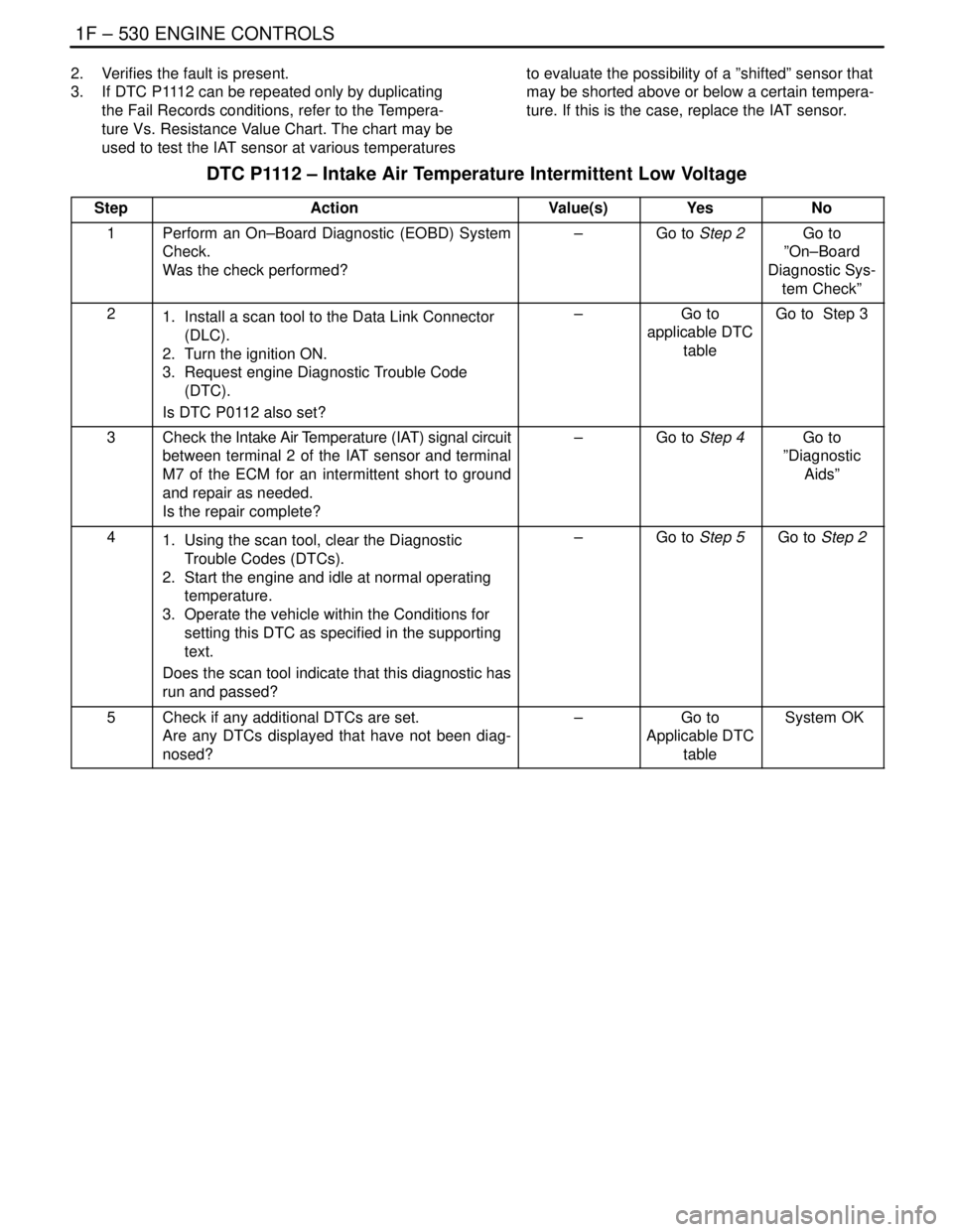
2. Verifies the fault is present.
3. If DTC P1112 can be repeated only by duplicating
the Fail Records conditions, refer to the Tempera-
ture Vs. Resistance Value Chart. The chart may be
used to test the IAT sensor at various temperaturesto evaluate the possibility of a ”shifted” sensor that
may be shorted above or below a certain tempera-
ture. If this is the case, replace the IAT sensor.
DTC P1112 – Intake Air Temperature Intermittent Low Voltage
StepActionValue(s)YesNo
1Perform an On–Board Diagnostic (EOBD) System
Check.
Was the check performed?–Go to Step 2Go to
”On–Board
Diagnostic Sys-
tem Check”
21. Install a scan tool to the Data Link Connector
(DLC).
2. Turn the ignition ON.
3. Request engine Diagnostic Trouble Code
(DTC).
Is DTC P0112 also set?–Go to
applicable DTC
tableGo to Step 3
3Check the Intake Air Temperature (IAT) signal circuit
between terminal 2 of the IAT sensor and terminal
M7 of the ECM for an intermittent short to ground
and repair as needed.
Is the repair complete?–Go to Step 4Go to
”Diagnostic
Aids”
41. Using the scan tool, clear the Diagnostic
Trouble Codes (DTCs).
2. Start the engine and idle at normal operating
temperature.
3. Operate the vehicle within the Conditions for
setting this DTC as specified in the supporting
text.
Does the scan tool indicate that this diagnostic has
run and passed?–Go to Step 5Go to Step 2
5Check if any additional DTCs are set.
Are any DTCs displayed that have not been diag-
nosed?–Go to
Applicable DTC
table System OK
Page 811 of 2643
ENGINE CONTROLS 1F – 565
DAEWOO V–121 BL4
DIAGNOSTIC TROUBLE CODE (DTC) P1404
EXHAUST GAS RECIRCULATION CLOSED VALVE
PINTLE ERROR
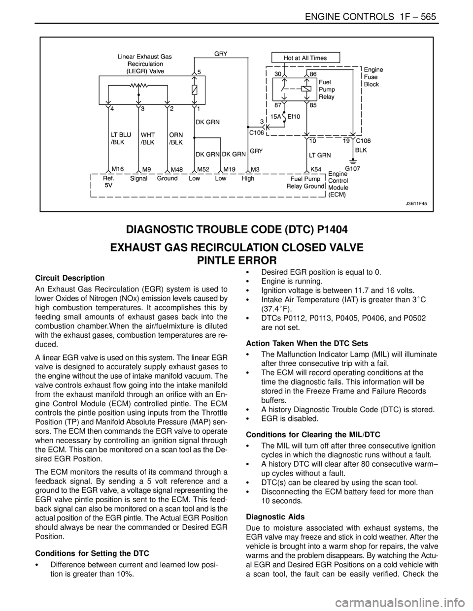
Circuit Description
An Exhaust Gas Recirculation (EGR) system is used to
lower Oxides of Nitrogen (NOx) emission levels caused by
high combustion temperatures. It accomplishes this by
feeding small amounts of exhaust gases back into the
combustion chamber.When the air/fuelmixture is diluted
with the exhaust gases, combustion temperatures are re-
duced.
A linear EGR valve is used on this system. The linear EGR
valve is designed to accurately supply exhaust gases to
the engine without the use of intake manifold vacuum. The
valve controls exhaust flow going into the intake manifold
from the exhaust manifold through an orifice with an En-
gine Control Module (ECM) controlled pintle. The ECM
controls the pintle position using inputs from the Throttle
Position (TP) and Manifold Absolute Pressure (MAP) sen-
sors. The ECM then commands the EGR valve to operate
when necessary by controlling an ignition signal through
the ECM. This can be monitored on a scan tool as the De-
sired EGR Position.
The ECM monitors the results of its command through a
feedback signal. By sending a 5 volt reference and a
ground to the EGR valve, a voltage signal representing the
EGR valve pintle position is sent to the ECM. This feed-
back signal can also be monitored on a scan tool and is the
actual position of the EGR pintle. The Actual EGR Position
should always be near the commanded or Desired EGR
Position.
Conditions for Setting the DTC
S Difference between current and learned low posi-
tion is greater than 10%.S Desired EGR position is equal to 0.
S Engine is running.
S Ignition voltage is between 11.7 and 16 volts.
S Intake Air Temperature (IAT) is greater than 3°C
(37.4°F).
S DTCs P0112, P0113, P0405, P0406, and P0502
are not set.
Action Taken When the DTC Sets
S The Malfunction Indicator Lamp (MIL) will illuminate
after three consecutive trip with a fail.
S The ECM will record operating conditions at the
time the diagnostic fails. This information will be
stored in the Freeze Frame and Failure Records
buffers.
S A history Diagnostic Trouble Code (DTC) is stored.
S EGR is disabled.
Conditions for Clearing the MIL/DTC
S The MIL will turn off after three consecutive ignition
cycles in which the diagnostic runs without a fault.
S A history DTC will clear after 80 consecutive warm–
up cycles without a fault.
S DTC(s) can be cleared by using the scan tool.
S Disconnecting the ECM battery feed for more than
10 seconds.
Diagnostic Aids
Due to moisture associated with exhaust systems, the
EGR valve may freeze and stick in cold weather. After the
vehicle is brought into a warm shop for repairs, the valve
warms and the problem disappears. By watching the Actu-
al EGR and Desired EGR Positions on a cold vehicle with
a scan tool, the fault can be easily verified. Check the
Page 822 of 2643
1F – 576IENGINE CONTROLS
DAEWOO V–121 BL4
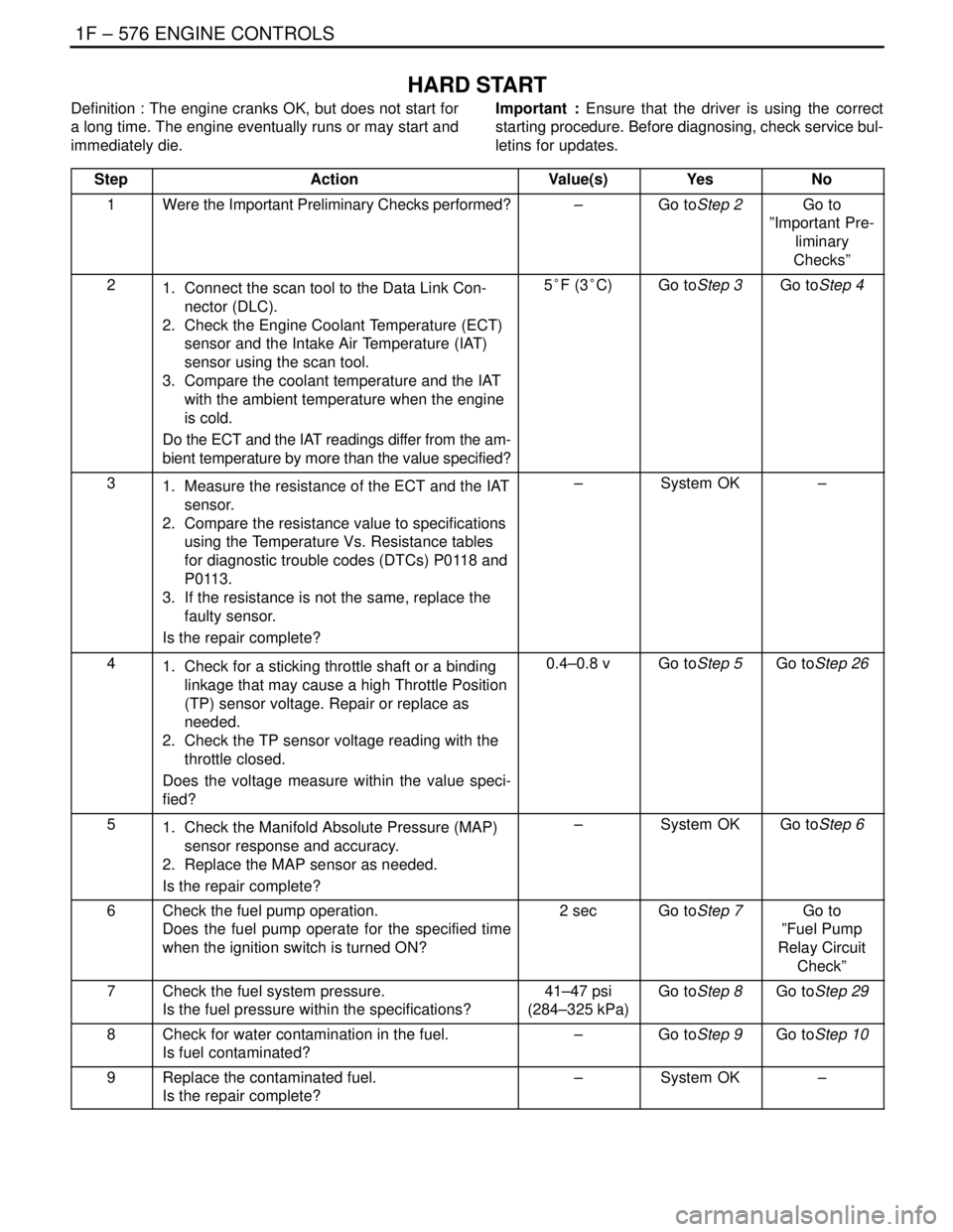
HARD START
Definition : The engine cranks OK, but does not start for
a long time. The engine eventually runs or may start and
immediately die.Important : Ensure that the driver is using the correct
starting procedure. Before diagnosing, check service bul-
letins for updates.
Step
ActionValue(s)YesNo
1Were the Important Preliminary Checks performed?–Go toStep 2Go to
”Important Pre-
liminary
Checks”
21. Connect the scan tool to the Data Link Con-
nector (DLC).
2. Check the Engine Coolant Temperature (ECT)
sensor and the Intake Air Temperature (IAT)
sensor using the scan tool.
3. Compare the coolant temperature and the IAT
with the ambient temperature when the engine
is cold.
Do the ECT and the IAT readings differ from the am-
bient temperature by more than the value specified?5°F (3°C)Go toStep 3Go toStep 4
31. Measure the resistance of the ECT and the IAT
sensor.
2. Compare the resistance value to specifications
using the Temperature Vs. Resistance tables
for diagnostic trouble codes (DTCs) P0118 and
P0113.
3. If the resistance is not the same, replace the
faulty sensor.
Is the repair complete?–System OK–
41. Check for a sticking throttle shaft or a binding
linkage that may cause a high Throttle Position
(TP) sensor voltage. Repair or replace as
needed.
2. Check the TP sensor voltage reading with the
throttle closed.
Does the voltage measure within the value speci-
fied?0.4–0.8 vGo toStep 5Go toStep 26
51. Check the Manifold Absolute Pressure (MAP)
sensor response and accuracy.
2. Replace the MAP sensor as needed.
Is the repair complete?–System OKGo toStep 6
6Check the fuel pump operation.
Does the fuel pump operate for the specified time
when the ignition switch is turned ON?2 secGo toStep 7Go to
”Fuel Pump
Relay Circuit
Check”
7Check the fuel system pressure.
Is the fuel pressure within the specifications?41–47 psi
(284–325 kPa)Go toStep 8Go toStep 29
8Check for water contamination in the fuel.
Is fuel contaminated?–Go toStep 9Go toStep 10
9Replace the contaminated fuel.
Is the repair complete?–System OK–
Page 846 of 2643

1F – 600IENGINE CONTROLS
DAEWOO V–121 BL4
7. Connect the fuel feed hose.
8. Connect the fuel injector harness connectors. Ro-
tate each fuel injector as required to avoid stretch-
ing the wireing harness.
9. Install the intake manifold bracket with the bolts.
10. Connect the negative battery cable.
11. Perform a leak check of the fuel rail and fuel injec-
tors.
FUEL RAIL AND INJECTORS
(1.8L DOHC)
Removal Procedure
CAUTION : The fuel system is under pressure. To
avoid fuel spillage and the risk of personal injury or
fire, it is necessary to relieve the fuel system pressure
before disconnecting the fuel lines.
1. Relieve the fuel system pressure. Refer to ” Fuel
System Pressure Relief ” in this section.
2. Disconnect the negative battery cable.
3. Disconnect the intake air temperature (IAT) sensor
connector.
4. Disconnect the breather hose from the valve cover.
5. Disconnect the positive crankcase ventilation (PCV)
hose from the valve cover.
6. Disconnect the throttle cables from the throttle body
and the bracket.
7. Disconnect the fuel feed line at the fuel rail.
8. Remove the fuel rail retaining bolts.
Page 849 of 2643

ENGINE CONTROLS 1F – 603
DAEWOO V–121 BL4
Installation Procedure
1. Coat the threads of the ECT sensor with sealer.
2. Install the ECT sensor into the EI system ignition
coil adapter.
Tighten
Tighten the engine coolant temperature sensor to 20
NSm (15 lb–ft).
3. Connect the ECT sensor connector.
4. Fill the coolant system.
5. Connect the negative battery cable.
THROTTLE POSITION SENSOR
(1.8L DOHC)
Removal Procedure
1. Disconnect the negative battery cable.
2. Remove the air intake tube and resonator.
3. Disconnect the throttle position (TP) sensor con-
nector.
4. Remove the TP sensor retaining bolts and the TP
sensor.
Installation Procedure
1. With the throttle valve closed, position the TP sen-
sor on the throttle shaft. Align the TP sensor with
the bolt holes.
2. Install the TP sensor retaining bolts.
Tighten
Tighten the throttle position sensor retaining bolts to
2 NSm (18 lb–in).
3. Connect the TP sensor connector.
4. Install the air intake tube and resonator.
5. Connect the negative battery cable.
THROTTLE BODY (1.4L/1.6L DOHC)
Removal Procedure
1. Disconnect the negative battery cable.
2. Remove the intake air tube.
3. Disconnect the breather hose.