2004 DAEWOO LACETTI Intake air temperature
[x] Cancel search: Intake air temperaturePage 650 of 2643

1F – 404IENGINE CONTROLS
DAEWOO V–121 BL4
DIAGNOSTIC TROUBLE CODE (DTC) P0172
FUEL TRIM SYSTEM TOO RICH
System Description
To provide the best possible combination of driveability,
fuel economy, and emission control, a Closed Loop air/fuel
metering system is used. While in Closed Loop, the En-
gine Control Module (ECM) monitors the Front Heated
Oxygen Sensor (HO2S1) signal voltage and adjusts fuel
delivery based on signal voltage. A change made to fuel
delivery will be indicated by the long and short term fuel
trim values which can be monitored with the scan tool.
Ideal fuel trim values are around 128 (0%). If the HO2S1
signal is indicating a lean condition, the ECM will add fuel
resulting in fuel trim values above 128 (0% to 100%). If a
rich condition is detected, the fuel trim values will be below
128 (0% to –100%), indicating that the ECM is reducing
the amount of fuel delivered. If exhaust emissions reach
an excessive level due to a lean or rich condition, a fuel
trim Diagnostic Trouble Code (DTC) is set.
Conditions for Setting the DTC
S The average of adaptive index multiplier value is
less than 0.75.
S No intrusive tests active.
S DTCs P0106, P0107, P0108, P0112, P0113,
P0117, P0118, P0122, P0123, P0131, P0132,
P0133, P0134, P0135, P1167, P1171, P0336,
P0337, P0341, P0342, P0402, P0404, P1404,
P0405, P0406, P0443, P0506, and P0507 are not
set.
S Throttle Position (TP) is less than 95%.
S Engine speed is between 700 and 6000 rpm.
S Barometric Pressure (BARO) is greater than 72.0
kPa (10.4 psi).
S Coolant temperature is between 70°C (158°F) and
11 5°C (239°F).
S Manifold Absolute Pressure (MAP) is between 25
kPa (3.6 psi) and 99.7 kPa (14.5 psi).
S Intake Air Temperature (IAT) is between –40°C
(–40°F) and 120°C (248°F).
S Airflow is between 1.5 and 45 g/sec.
S Vehicle speed is less than 140 km/h (87 mph).
S System is in closed loop.
S Adaptive index is ready.
S System voltage is greater than 11 volts.
Action Taken When the DTC Sets
S The Malfunction Indicator Lamp (MIL) will illuminate
after two consecutive ignitions cycle in which the
diagnostic runs with the fault active (SOHC).
S The Malfunction Indicator Lamp (MIL) will illuminate
after first consecutive ignitions cycle (DOHC).
S The ECM will record operating conditions at the
time the diagnostic fails. This information will be
stored in the Freeze Frame and Failure Records
buffers.
S A history DTC is stored.Conditions for Clearing the MIL/DTC
S The MIL will turn off after two consecutive ignition
cycles in which the diagnostic runs without a fault
within the freeze frame conditions that the DTC
failed.
S A history DTC will clear after 40 consecutive warm–
up cycles without a fault.
S The DTC(s) can be cleared by using the scan tool.
S Disconnecting the ECM battery feed for more than
10 seconds.
Diagnostic Aids
Important : After repairs, use the scan tool Fuel Trim Re-
set function to reset the long–term fuel trim to 128 (0%).
Check for poor connection at the ECM. Inspect the har-
ness connectors for the following conditions:
S Backed–out terminals.
S Improper mating.
S Broken locks.
S Improperly formed.
S Damaged terminals.
S Poor terminal–to–wire connection.
Inspect the wiring harness for damage. If the harness ap-
pears to be OK, observe the HO2S1 display on the scan
tool while moving the connectors and the wiring harness
related to the engine harness. A change in the display will
indicate the location of the fault.
If a DTC P1404 is also set, check the 5 volt reference cir-
cuits for a short to voltage.
Check for a restricted exhaust system.
A shorted 5 volt reference circuit may cause a DTC P0172
to set. Check the 5 volt reference sensors for abnormal
readings.
Test Description
Number(s) below refer to the step number(s) on the Diag-
nostic Table.
1. The On–Board Diagnostic (EOBD) System Check
prompts the technician to complete some basic
checks and store the freeze frame and failure re-
cords data on the scan tool if applicable. This
creates an electronic copy of the data taken when
the malfunction occurred. The information is then
stored on the scan tool for later reference.
5. A clogged air cleaner filter element restricts the air-
flow coming into the engine. This step checks the
condition of the air cleaner filter.
17. A leaky injector can cause a rich condition and set
DTC P0172. Refer to ”Fuel Injector Balance Test”
in this section.
19. A loose TP sensor may not set a TP sensor related
DTC, but may cause the system to become rich by
a higher–than–actual TP reading.
Page 667 of 2643

ENGINE CONTROLS 1F – 421
DAEWOO V–121 BL4
DIAGNOSTIC TROUBLE CODE (DTC) P0300
MULTIPLE CYLINDER MISFIRE DETECTED
System Description
The Engine Control Module (ECM) monitors the crank-
shaft and camshaft positions to detect if the engine is mis-
firing. The ECM looks for a quick drop in crankshaft speed.
This test is executed in blocks of 100 engine revolution
tests. It may take between one to several tests to store a
Diagnostic Trouble Code (DTC) and illuminate the Mal-
function Indicator Lamp (MIL). Under light misfire condi-
tions, it may also take more than one trip to set a DTC. Se-
vere misfire will flash the MIL, indicating that catalyst
damage is possible.
Conditions for Setting the DTC
S Emission threshold is 3%.
S 20 engine cycles have occurred since cranking has
started.
S A/C compressor clutch has not just engaged or dis-
engaged.
S Engine load and engine speed is in a detectable
region and is at or above zero torque.
S Camshaft Position (CMP) sensor is in synchroniza-
tion.
S Exhaust Gas Recirculation (EGR) flow diagnostic is
not in progress.
S Fuel level is greater than 12% of rated tank capac-
ity.
S Decel Fuel Cutoff (DFCO) not active.
S Throttle position change is less than 3% per 125
ms.
S Vehicle has not encountered an abusive engine
speed of 7000 rpm.
S Crankshaft speed patters are normal.
S Throttle position is less than 3% when vehicle
speed is greater than 10 km/h (6 mph).
S Vehicle voltage is between 11 and 16 volts.
S Engine Coolant Temperature (ECT) is between
–7°C (19°F) and 120°C (248°F).
S There is the correct ratio between Crankshaft Posi-
tion (CKP) sensor pulses and CMP sensor pulses.
S DTCs P0106, P0107, P0108, P0117, P0118,
P0122, P0123, P0336, P0337, P0341, P0342 and
P0502 are not set.
Action Taken When the DTC Sets
S The MIL will illuminate after two consecutive ignition
cycles in which the diagnostic runs with the fault
active.
Or
S The MIL will illuminate immediately and flash if mis-
fire is present.
S The ECM will record operating conditions at the
time the diagnostic fails. This information will be
stored in the Freeze Frame and Failure Records
buffers.S A history DTC is stored.
Conditions for Clearing the MIL/DTC
S The MIL will turn off after four consecutive ignition
cycles in which the diagnostic runs without a fault
within the freeze frame conditions that the DTC
failed.
S A history DTC will clear after 40 consecutive warm–
up cycles without a fault.
S The DTC(s) can be cleared by using the scan tool.
S Disconnecting the ECM battery feed for more than
10 seconds.
Diagnostic Aids
An intermittent can also be the result of a defective reluctor
wheel. Remove the CKP sensor and inspect the reluctor
wheel through the sensor mount hole. Check for porosity
and the condition of wheel. If the DTC is intermittent refer
to ”Symptoms Diagnosis” in this section.
Test Description
Number(s) below refer to the step number(s) on the Diag-
nostic Table.
1. The On–Board Diagnostic (EOBD) System Check
prompts the technician to complete some basic
checks and store the freeze frame and failure re-
cords data on the scan tool if applicable. This
creates an electronic copy of the data taken when
the malfunction occurred. The information is then
stored on the scan tool for later reference.
3. A visual/physical inspection should include check-
ing the following components:
S The wiring for proper connections, pinches or
cuts.
S The ECM grounds for being clean and tight.
S The vacuum hoses for splits, kinks, and proper
connections as shown on the Vehicle Emission
Information label. Check thoroughly for any type
of leak or restriction.
S For air leaks at the throttle body mounting area
and intake manifold sealing surfaces.
5. When all the accumulators are relatively equal, then
the misfire is being caused by something that af-
fects the entire engine. When they are not then the
misfire is being caused by something that is specif-
ic to two or more cylinders.
6. Whenever the misfire is not present operating the
vehicle may be necessary to duplicate the condi-
tions in the Freeze Frame Data in order to detect
misfire. Depending on the engine load, the condi-
tions may have to be maintained for up to 20 sec-
onds. Whenever the misfire accumulators start to
increment, then misfire is present. A history misfire
counter will store the number of misfires that have
occurred until the DTC is cleared.
Page 672 of 2643

1F – 426IENGINE CONTROLS
DAEWOO V–121 BL4
DIAGNOSTIC TROUBLE CODE (DTC) P0301
CYLINDER 1 MISFURE
System Description
The Engine Control Module (ECM) monitors the crank-
shaft and camshaft positions to detect if the engine is mis-
firing. The ECM looks for a quick drop in crankshaft speed.
This test is executed in blocks of 100 engine revolution
tests. It may take between one to several tests to store a
Diagnostic Trouble Code (DTC) and illuminate the Mal-
function Indicator Lamp (MIL). Under light misfire condi-
tions, it may also take more than one trip to set a DTC. Se-
vere misfire will flash the MIL, indicating that catalyst
damage is possible.
Conditions for Setting the DTC
S Emission threshold is 3%.
S 20 engine cycles have occurred since cranking has
started.
S A/C compressor clutch has not just engaged or dis-
engaged.
S Engine load and engine speed is in a detectable
region and is at or above zero torque.
S Camshaft Position (CMP) sensor is in synchroniza-
tion.
S Exhaust Gas Recirculation (EGR) flow diagnostic is
not in progress.
S Fuel level is greater than 12% of rated tank capac-
ity.
S Decel Fuel Cutoff (DFCO) not active.
S Throttle position change is less than 3% per 125
ms.
S Vehicle has not encountered an abusive engine
speed of 7000 rpm.
S Crankshaft speed patters are normal.
S Throttle position is less than 3% when vehicle
speed is greater than 10 km/h (6 mph).
S Vehicle voltage is between 11 and 16 volts.
S Engine Coolant Temperature (ECT) is between
–7°C (19°F) and 120°C (248°F).
S There is the correct ratio between Crankshaft Posi-
tion (CKP) sensor pulses and CMP sensor pulses.
S DTCs P0106, P0107, P0108, P0117, P0118,
P0122, P0123, P0336, P0337, P0341, P0342 and
P0502 are not set.
Action Taken When the DTC Sets
S The MIL will illuminate after two consecutive ignition
cycles in which the diagnostic runs with the fault
active.
Or
S The MIL will illuminate immediately and flash if mis-
fire is present.S The ECM will record operating conditions at the
time the diagnostic fails. This information will be
stored in the Freeze Frame and Failure Records
buffers.
S A history DTC is stored.
Conditions for Clearing the MIL/DTC
S The MIL will turn off after four consecutive ignition
cycles in which the diagnostic runs without a fault
within the freeze frame conditions that the DTC
failed.
S A history DTC will clear after 40 consecutive warm–
up cycles without a fault.
S The DTC(s) can be cleared by using the scan tool.
S Disconnecting the ECM battery feed for more than
10 seconds.
Diagnostic Aids
An intermittent can also be the result of a defective reluctor
wheel. Remove the CKP sensor and inspect the reluctor
wheel through the sensor mount hole. Check for porosity
and the condition of wheel. If the DTC is intermittent refer
to ”Symptoms Diagnosis” in this section.
Test Description
Number(s) below refer to the step number(s) on the Diag-
nostic Table.
1. The On–Board Diagnostic (EOBD) System Check
prompts the technician to complete some basic
checks and store the freeze frame and failure re-
cords data on the scan tool if applicable. This
creates an electronic copy of the data taken when
the malfunction occurred. The information is then
stored on the scan tool for later reference.
3. A visual/physical inspection should include check-
ing the following components:
S The wiring for proper connections, pinches or
cuts.
S The ECM grounds for being clean and tight.
S The vacuum hoses for splits, kinks, and proper
connections as shown on the Vehicle Emission
Information label.
S Check thoroughly for any type of leak or restric-
tion.
S For air leaks at the throttle body mounting area
and intake manifold sealing surfaces.
5. When all the accumulators are relatively equal, then
the misfire is being caused by something that af-
fects the entire engine. When they are not then the
misfire is being caused by something that is specif-
ic to two or more cylinders.
6. Whenever the misfire is not present operating the
vehicle may be necessary to duplicate the condi-
tions in the Freeze Frame Data in order to detect
Page 677 of 2643

ENGINE CONTROLS 1F – 431
DAEWOO V–121 BL4
DIAGNOSTIC TROUBLE CODE (DTC) P0302
CYLINDER 2 MISFIRE
System Description
The Engine Control Module (ECM) monitors the crank-
shaft and camshaft positions to detect if the engine is mis-
firing. The ECM looks for a quick drop in crankshaft speed.
This test is executed in blocks of 100 engine revolution
tests. It may take between one to several tests to store a
Diagnostic Trouble Code (DTC) and illuminate the Mal-
function Indicator Lamp (MIL). Under light misfire condi-
tions, it may also take more than one trip to set a DTC. Se-
vere misfire will flash the MIL, indicating that catalyst
damage is possible.
Conditions for Setting the DTC
S Emission threshold is 3%.
S 20 engine cycles have occurred since cranking has
started.
S A/C compressor clutch has not just engaged or dis-
engaged.
S Engine load and engine speed is in a detectable
region and is at or above zero torque.
S Camshaft Position (CMP) sensor is in synchroniza-
tion.
S Exhaust Gas Recirculation (EGR) flow diagnostic is
not in progress.
S Fuel level is greater than 12% of rated tank capac-
ity.
S Decel Fuel Cutoff (DFCO) not active.
S Throttle position change is less than 3% per 125
ms.
S Vehicle has not encountered an abusive engine
speed of 7000 rpm.
S Crankshaft speed patters are normal.
S Throttle position is less than 3% when vehicle
speed is greater than 10 km/h (6 mph).
S Vehicle voltage is between 11 and 16 volts.
S Engine Coolant Temperature (ECT) is between
–7°C (19°F) and 120°C (248°F).
S There is the correct ratio between Crankshaft Posi-
tion (CKP) sensor pulses and CMP sensor pulses.
S DTCs P0106, P0107, P0108, P0117, P0118,
P0122, P0123, P0336, P0337, P0341, P0342 and
P0502 are not set.
Action Taken When the DTC Sets
S The MIL will illuminate after two consecutive ignition
cycles in which the diagnostic runs with the fault
active.
Or
S The MIL will illuminate immediately and flash if mis-
fire is present.
S The ECM will record operating conditions at the
time the diagnostic fails. This information will be
stored in the Freeze Frame and Failure Records
buffers.S A history DTC is stored.
Conditions for Clearing the MIL/DTC
S The MIL will turn off after four consecutive ignition
cycles in which the diagnostic runs without a fault
within the freeze frame conditions that the DTC
failed.
S A history DTC will clear after 40 consecutive warm–
up cycles without a fault.
S The DTC(s) can be cleared by using the scan tool.
S Disconnecting the ECM battery feed for more than
10 seconds.
Diagnostic Aids
An intermittent can also be the result of a defective reluctor
wheel. Remove the CKP sensor and inspect the reluctor
wheel through the sensor mount hole. Check for porosity
and the condition of wheel. If the DTC is intermittent refer
to”Symptoms Diagnosis” in this section.
Test Description
Number(s) below refer to the step number(s) on the Diag-
nostic Table.
1. The On–Board Diagnostic (EOBD) System Check
prompts the technician to complete some basic
checks and store the freeze frame and failure re-
cords data on the scan tool if applicable. This
creates an electronic copy of the data taken when
the malfunction occurred. The information is then
stored on the scan tool for later reference.
3. A visual/physical inspection should include check-
ing the following components:
S The wiring for proper connections, pinches or
cuts.
S The ECM grounds for being clean and tight.
S The vacuum hoses for splits, kinks, and proper
connections as shown on the Vehicle Emission
Information label. Check thoroughly for any type
of leak or restriction.
S For air leaks at the throttle body mounting area
and intake manifold sealing surfaces.
5. When all the accumulators are relatively equal, then
the misfire is being caused by something that af-
fects the entire engine. When they are not then the
misfire is being caused by something that is specif-
ic to two or more cylinders.
6. Whenever the misfire is not present operating the
vehicle may be necessary to duplicate the condi-
tions in the Freeze Frame Data in order to detect
misfire. Depending on the engine load, the condi-
tions may have to be maintained for up to 20 sec-
onds. Whenever the misfire accumulators start to
increment, then misfire is present. A history misfire
counter will store the number of misfires that have
occurred until the DTC is cleared.
Page 682 of 2643

1F – 436IENGINE CONTROLS
DAEWOO V–121 BL4
DIAGNOSTIC TROUBLE CODE (DTC) P0303
CYLINDER 3 MISFIRE
System Description
The Engine Control Module (ECM) monitors the crank-
shaft and camshaft positions to detect if the engine is mis-
firing. The ECM looks for a quick drop in crankshaft speed.
This test is executed in blocks of 100 engine revolution
tests. It may take between one to several tests to store a
Diagnostic Trouble Code (DTC) and illuminate the Mal-
function Indicator Lamp (MIL). Under light misfire condi-
tions, it may also take more than one trip to set a DTC. Se-
vere misfire will flash the MIL, indicating that catalyst
damage is possible.
Conditions for Setting the DTC
S Emission threshold is 3%.
S 20 engine cycles have occurred since cranking has
started.
S A/C compressor clutch has not just engaged or dis-
engaged.
S Engine load and engine speed is in a detectable
region and is at or above zero torque.
S Camshaft Position (CMP) sensor is in synchroniza-
tion.
S Exhaust Gas Recirculation (EGR) flow diagnostic is
not in progress.
S Fuel level is greater than 12% of rated tank capac-
ity.
S Decel Fuel Cutoff (DFCO) not active.
S Throttle position change is less than 3% per 125
ms.
S Vehicle has not encountered an abusive engine
speed of 7000 rpm.
S Crankshaft speed patters are normal.
S Throttle position is less than 3% when vehicle
speed is greater than 10 km/h (6 mph).
S Vehicle voltage is between 11 and 16 volts.
S Engine Coolant Temperature (ECT) is between
–7°C (19°F) and 120°C (248°F).
S There is the correct ratio between Crankshaft Posi-
tion (CKP) sensor pulses and CMP sensor pulses.
S DTCs P0106, P0107, P0108, P0117, P0118,
P0122, P0123, P0336, P0337, P0341, P0342 and
P0502 are not set.
Action Taken When the DTC Sets
S The MIL will illuminate after two consecutive ignition
cycles in which the diagnostic runs with the fault
active.
Or
S The MIL will illuminate immediately and flash if mis-
fire is present.
S The ECM will record operating conditions at the
time the diagnostic fails. This information will be
stored in the Freeze Frame and Failure Records
buffers.S A history DTC is stored.
Conditions for Clearing the MIL/DTC
S The MIL will turn off after four consecutive ignition
cycles in which the diagnostic runs without a fault
within the freeze frame conditions that the DTC
failed.
S A history DTC will clear after 40 consecutive warm–
up cycles without a fault.
S The DTC(s) can be cleared by using the scan tool.
S Disconnecting the ECM battery feed for more than
10 seconds.
Diagnostic Aids
An intermittent can also be the result of a defective reluctor
wheel. Remove the CKP sensor and inspect the reluctor
wheel through the sensor mount hole. Check for porosity
and the condition of wheel. If the DTC is intermittent refer
to”Symptoms Diagnosis” in this section.
Test Description
Number(s) below refer to the step number(s) on the Diag-
nostic Table.
1. The On–Board Diagnostic (EOBD) System Check
prompts the technician to complete some basic
checks and store the freeze frame and failure re-
cords data on the scan tool if applicable. This
creates an electronic copy of the data taken when
the malfunction occurred. The information is then
stored on the scan tool for later reference.
3. A visual/physical inspection should include check-
ing the following components:
S The wiring for proper connections, pinches or
cuts.
S The ECM grounds for being clean and tight.
S The vacuum hoses for splits, kinks, and proper
connections as shown on the Vehicle Emission
Information label. Check thoroughly for any type
of leak or restriction.
S For air leaks at the throttle body mounting area
and intake manifold sealing surfaces.
5. When all the accumulators are relatively equal, then
the misfire is being caused by something that af-
fects the entire engine. When they are not then the
misfire is being caused by something that is specif-
ic to two or more cylinders.
6. Whenever the misfire is not present operating the
vehicle may be necessary to duplicate the condi-
tions in the Freeze Frame Data in order to detect
misfire. Depending on the engine load, the condi-
tions may have to be maintained for up to 20 sec-
onds. Whenever the misfire accumulators start to
increment, then misfire is present. A history misfire
counter will store the number of misfires that have
occurred until the DTC is cleared.
Page 687 of 2643

ENGINE CONTROLS 1F – 441
DAEWOO V–121 BL4
DIAGNOSTIC TROUBLE CODE (DTC) P0304
CYLINDER 4 MISFIRE
System Description
The Engine Control Module (ECM) monitors the crank-
shaft and camshaft positions to detect if the engine is mis-
firing. The ECM looks for a quick drop in crankshaft speed.
This test is executed in blocks of 100 engine revolution
tests. It may take between one to several tests to store a
Diagnostic Trouble Code (DTC) and illuminate the Mal-
function Indicator Lamp (MIL). Under light misfire condi-
tions, it may also take more than one trip to set a DTC. Se-
vere misfire will flash the MIL, indicating that catalyst
damage is possible.
Conditions for Setting the DTC
S Emission threshold is 3%.
S 20 engine cycles have occurred since cranking has
started.
S A/C compressor clutch has not just engaged or dis-
engaged.
S Engine load and engine speed is in a detectable
region and is at or above zero torque.
S Camshaft Position (CMP) sensor is in synchroniza-
tion.
S Exhaust Gas Recirculation (EGR) flow diagnostic is
not in progress.
S Fuel level is greater than 12% of rated tank capac-
ity.
S Decel Fuel Cutoff (DFCO) not active.
S Throttle position change is less than 3% per 125
ms.
S Vehicle has not encountered an abusive engine
speed of 7000 rpm.
S Crankshaft speed patters are normal.
S Throttle position is less than 3% when vehicle
speed is greater than 10 km/h (6 mph).
S Vehicle voltage is between 11 and 16 volts.
S Engine Coolant Temperature (ECT) is between
–7°C (19°F) and 120°C (248°F).
S There is the correct ratio between Crankshaft Posi-
tion (CKP) sensor pulses and CMP sensor pulses.
S DTCs P0106, P0107, P0108, P0117, P0118,
P0122, P0123, P0336, P0337, P0341, P0342 and
P0502 are not set.
Action Taken When the DTC Sets
S The MIL will illuminate after two consecutive ignition
cycles in which the diagnostic runs with the fault
active.
Or
S The MIL will illuminate immediately and flash if mis-
fire is present.
S The ECM will record operating conditions at the
time the diagnostic fails. This information will be
stored in the Freeze Frame and Failure Records
buffers.S A history DTC is stored.
Conditions for Clearing the MIL/DTC
S The MIL will turn off after four consecutive ignition
cycles in which the diagnostic runs without a fault
within the freeze frame conditions that the DTC
failed.
S A history DTC will clear after 40 consecutive warm–
up cycles without a fault.
S The DTC(s) can be cleared by using the scan tool.
S Disconnecting the ECM battery feed for more than
10 seconds.
Diagnostic Aids
An intermittent can also be the result of a defective reluctor
wheel. Remove the CKP sensor and inspect the reluctor
wheel through the sensor mount hole. Check for porosity
and the condition of wheel. If the DTC is intermittent refer
to”Symptoms Diagnosis” in this section.
Test Description
Number(s) below refer to the step number(s) on the Diag-
nostic Table.
1. The On–Board Diagnostic (EOBD) System Check
prompts the technician to complete some basic
checks and store the freeze frame and failure re-
cords data on the scan tool if applicable. This
creates an electronic copy of the data taken when
the malfunction occurred. The information is then
stored on the scan tool for later reference.
3. A visual/physical inspection should include check-
ing the following components:
S The wiring for proper connections, pinches or
cuts.
S The ECM grounds for being clean and tight.
S The vacuum hoses for splits, kinks, and proper
connections as shown on the Vehicle Emission
Information label. Check thoroughly for any type
of leak or restriction.
S For air leaks at the throttle body mounting area
and intake manifold sealing surfaces.
5. When all the accumulators are relatively equal, then
the misfire is being caused by something that af-
fects the entire engine. When they are not then the
misfire is being caused by something that is specif-
ic to two or more cylinders.
6. Whenever the misfire is not present operating the
vehicle may be necessary to duplicate the condi-
tions in the Freeze Frame Data in order to detect
misfire. Depending on the engine load, the condi-
tions may have to be maintained for up to 20 sec-
onds. Whenever the misfire accumulators start to
increment, then misfire is present. A history misfire
counter will store the number of misfires that have
occurred until the DTC is cleared.
Page 714 of 2643

1F – 468IENGINE CONTROLS
DAEWOO V–121 BL4
DIAGNOSTIC TROUBLE CODE (DTC) P0401
EXHAUST GAS RECIRCULATION INSUFFICIENT FLOW
Circuit Description
An Exhaust Gas Recirculation (EGR) system is used to
lower Nitrogen Oxide (NOx) emission levels caused by
high combustion temperatures. It accomplishes this by
feeding small amounts of exhaust gases back into the
combustion chamber. When the air/fuel mixture is diluted
with the exhaust gases, combustion temperatures are re-
duced
A linear EGR valve is used on this system. The linear EGR
valve is designed to accurately supply exhaust gases to
the engine without the use of intake manifold vacuum. The
valve controls exhaust flow going into the intake manifold
from the exhaust manifold through an orifice with an En-
gine Control Module (ECM) controlled pintle. The ECM
controls the pintle position using inputs from the Throttle
Position (TP) and Manifold Absolute Pressure (MAP) sen-
sors. The ECM then commands the EGR valve to operate
when necessary by controlling an ignition signal through
the ECM. This can be monitored on a scan tool as the De-
sired EGR Position.
The ECM monitors the results of its command through a
feedback signal. By sending a 5 volt reference and a
ground to the EGR valve, a voltage signal representing the
EGR valve pintle position is sent to the ECM. This feed-
back signal can also be monitored on a scan tool and is the
actual position of the EGR pintle. The Actual EGR Position
should always be near the commanded or Desired EGR
Position.
This diagnostic will determine if there is a reduction in EGR
flow.
Conditions for Setting the DTC
S DTCs P0106, P0107, P0108, P0117, P0118,
P0122, P0123, P0201, P0202, P0203, P0204,
P0351, P0352, P0402, P0404, P1404, P0405,
P0406 and P0502 are not set.
S Test in Decel Fuel Cutoff (DFCO) mode.
S Barometric Pressure (BARO) is greater than 72
kPa (10.4 psi).
S Vehicle speed is greater than 18 km/h (11.2
mph).
S A/C clutch/transmission clutch are unchanged.
S Rpm is between 1400 and 3000 for manual
transaxle.
S Rpm is between 1300 and 2900 for automatic
transaxle.
S Compensated MAP is with 10.3 to 32 kpa (1.5 to
4.6 psi) range.
S Start test
S Throttle position (TP) sensor is less then 1%.
S EGR is less than 1%.
S Change in MAP is less than 1.0 kpa (0.15 psi)Note : Test will be aborted when:
S Change in vehicle speed is greater than 5km/h (3.1
mph).
S Rpm is increased more than 75.
S EGR opened less than 90% commanded position.
Action Taken When the DTC Sets
S The Malfunction Indicator Lamp (MIL) will not illumi-
nate.
S The ECM will store conditions which were present
when the DTC set as Failure Records data only.
This information will not be stored in the Freeze
Frame data.
S A history Diagnostic Trouble Code (DTC) is stored.
S EGR is disabled.
Conditions for Clearing the MIL/DTC
S A history DTC will clear after 40 consecutive warm–
up cycles without a fault.
S DTC(s) can be cleared by using the scan tool.
S Disconnecting the ECM battery feed for more than
10 seconds.
Diagnostic Aids
The EGR Decel Filter value can be a great aid in determin-
ing if a problem exists and to verify repairs. The EGR De-
cel Filter is an average of the difference in the expected
MAP change and the actual MAP change caused by open-
ing the EGR valve during a deceleration, and is used to de-
termine when the MIL is illuminated. By driving the vehicle
up to approximately 97 km/h (60 mph) and decelerating to
32 km/h (20 mph), it can be determined if the EGR system
is OK, partially restricted, or fully restricted.
A more negative number (less than –3) indicates that the
system is working normally, whereas a positive number in-
dicates that the system is being restricted and that the ex-
pected amount of EGR flow is was not seen. A number
that falls between negative 3 and positive 2 indicates that
the system is partially restricted but not restricted enough
to cause an emissions impact.
The EGR Decel Filter value should always be at –3 or low-
er. If the EGR Decel Filter number becomes more positive
(towards 0 or more), then the EGR system is becoming re-
stricted. Look for possible damage to the EGR pipe or for
a restriction caused by carbon deposits in the EGR pas-
sages or on the EGR valve.
Test Description
Number(s) below refer to the step number(s) on the Diag-
nostic Table.
1. The On–Board Diagnostic (EOBD) System Check
prompts the technician to complete some basic
checks and store the freeze frame and failure re-
cords data on the scan tool if applicable. This
Page 716 of 2643
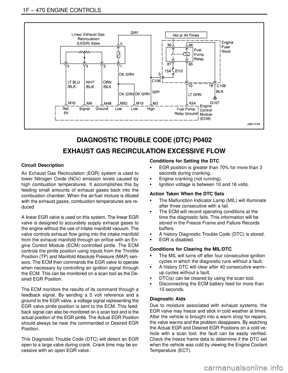
1F – 470IENGINE CONTROLS
DAEWOO V–121 BL4
DIAGNOSTIC TROUBLE CODE (DTC) P0402
EXHAUST GAS RECIRCULATION EXCESSIVE FLOW
Circuit Description
An Exhaust Gas Recirculation (EGR) system is used to
lower Nitrogen Oxide (NOx) emission levels caused by
high combustion temperatures. It accomplishes this by
feeding small amounts of exhaust gases back into the
combustion chamber. When the air/fuel mixture is diluted
with the exhaust gases, combustion temperatures are re-
duced
A linear EGR valve is used on this system. The linear EGR
valve is designed to accurately supply exhaust gases to
the engine without the use of intake manifold vacuum. The
valve controls exhaust flow going into the intake manifold
from the exhaust manifold through an orifice with an En-
gine Control Module (ECM) controlled pintle. The ECM
controls the pintle position using inputs from the Throttle
Position (TP) and Manifold Absolute Pressure (MAP) sen-
sors. The ECM then commands the EGR valve to operate
when necessary by controlling an ignition signal through
the ECM. This can be monitored on a scan tool as the De-
sired EGR Position.
The ECM monitors the results of its command through a
feedback signal. By sending a 5 volt reference and a
ground to the EGR valve, a voltage signal representing the
EGR valve pintle position is sent to the ECM. This feed-
back signal can also be monitored on a scan tool and is the
actual position of the EGR pintle. The Actual EGR Position
should always be near the commanded or Desired EGR
Position.
This Diagnostic Trouble Code (DTC) will detect an EGR
open to a large valve during crank. Crank time may be ex-
cessive with an open EGR valve.Conditions for Setting the DTC
S EGR position is greater than 70% for more than 3
seconds during cranking.
S Engine cranking (not running).
S Ignition voltage is between 10 and 16 volts.
Action Taken When the DTC Sets
S The Malfunction Indicator Lamp (MIL) will illuminate
after three consecutive with a fail.
S The ECM will record operating conditions at the
time the diagnostic fails. This information will be
stored in the Freeze Frame and Failure Records
buffers.
S A history Diagnostic Trouble Code (DTC) is stored.
S EGR is disabled.
Conditions for Clearing the MIL/DTC
S The MIL will turns off after four consecutive ignition
cycles in which the diagnostic runs without a fault.
S A history DTC will clear after 40 consecutive warm–
up cycles without a fault.
S DTC(s) can be cleared by using the scan tool.
S Disconnecting the ECM battery feed for more than
10 seconds.
Diagnostic Aids
Due to moisture associated with exhaust systems, the
EGR valve may freeze and stick in cold weather at times.
After the vehicle is brought into a warm shop for repairs,
the valve warms and the problem disappears. By watching
the Actual EGR and Desired EGR Positions on a cold ve-
hicle with a scan tool, the fault can be easily verified.
Check the freeze frame data to determine if the DTC set
when the vehicle was cold by viewing the Engine Coolant
Temperature (ECT).