2004 DAEWOO LACETTI Fuel tank
[x] Cancel search: Fuel tankPage 19 of 2643

0B – 12IGENERAL INFORMATION
DAEWOO V–121 BL4
OWNER INSPECTIONS AND SERVICES
WHLE OPERATING THE VEHICLE
Horn Operation
Blow the horn occasionally tomake sure it works. Check
all the button locations.
Brake System Operation
Be alert for abnormal sounds, increased brake pedal trav-
el or repeated pulling to one side when braking. Also, if the
brake warning light goes on, or flashes, something may be
wrong with part of the brake system.
Exhaust System Operation
Be alert to any changes in the sound of the system or the
smell of the fumes. These are signs that the system may
be leaking or overheating. Have the system inspected and
repaired immediately.
Tires,Wheels and Alignment Operation
Be alert to any vibration of the steering wheel or the seats
at normal highway speeds. This may mean a wheel needs
to be balanced. Also, a pull right or left on a straight, level
road may show the need for a tire pressure adjustment or
a wheel alignment.
Steering System Operation
Be alert to changes in the steering action. An inspection
is needed when the steering wheel is hard to turn or has
too much free play, or if unusual sounds are noticed when
turning or parking.
Headlight Aim
Take note of the light pattern occasionally. Adjust the
headlights if the beams seem improperly aimed.
AT EACH FUEL FILL
A fluid loss in any (except windshield washer) system may
indicate a problem. Have the system inspected and re-
paired immediately.
Engine Oil Level
Check the oil level and add oil if necessary. The best time
to check the engine oil level is when the oil is warm.
1. After stopping the engine, wait a few minutes for
the oil to drain back to the oil pan.
2. Pull out the oil level indicator (dip stick).
3. Wipe it clean, and push the oil level indicator back
down all the way.
4. Pull out the oil level indicator and look at the oil lev-
el on it.
5. Add oil, if needed, to keep the oil level above the
MIN line and within the area labeled ”Operating
Range.” Avoid overfilling the engine, since this may
cause engine damage.
6. Push the indicator all the way back down into the
engine after taking the reading.If you check the oil level when the oil is cold, do not run the
engine first. The cold oil will not drain back to the pan fast
enough to give a true oil level reading.
Engine Coolant Level and Condition
Check the coolant level in the coolant reservoir tank and
add coolant if necessary. Inspect the coolant. Replace
dirty or rusty coolant.
Windshield Washer Fluid Level
Check the washer fluid level in the reservoir. Add fluid if
necessary.
AT LEAST MONTHLY
Tire And Wheel Inspection and Pressure
Check
Check the tires for abnormal wear or damage. Also check
for damaged wheels. Check the tire pressure when the
tires are cold (check the spare also, unless it is a stow-
away). Maintain the recommended pressures that are on
the tire placard that is in the glove box.
Light Operation
Check the operation of the license plate light, the head-
lights (including the high beams), the parking lights, the
fog lights, the taillight, the brake lights, the turn signals, the
backup lights and the hazard warning flasher.
Fluid Leak Check
Periodically inspect the surface beneath the vehicle for
water, oil, fuel or other fluids, after the vehicle has been
parked for a while. Water dripping from the air conditioning
system after use is normal. If you notice fuel leaks or
fumes, find the cause and correct it at once.
AT LEAST TWICE A YEAR
Power Steering System Reservoir Level
Check the power steering fluid level. Keep the power
steering fluid at the proper level. Refer to Section 6A, Pow-
er Steering System.
Brake Master Cylinder Reservoir Level
Check the fluid and keep it at the proper level. A low fluid
level can indicate worn disc brake pads which may need
to be serviced. Check the breather hole in the reservoir
cover to be free from dirt and check for an open passage.
Clutch Pedal Free Travel
Check clutch pedal free travel and adjust as necessary.
Measure the distance from the center of the clutch pedal
to the outer edge of the steering wheel with the clutch ped-
al not depressed. Then measure the distance from the
center of the clutch pedal to the outer edge of the steering
wheel with the clutch pedal fully depressed. The difference
between the two values must be greater than 130 mm
(5.19 inches).
Weather–Strip Lubrication
Apply a thin film silicone grease using a clean cloth.
Page 28 of 2643
GENERAL INFORMATION 0B – 21
DAEWOO V–121 BL4
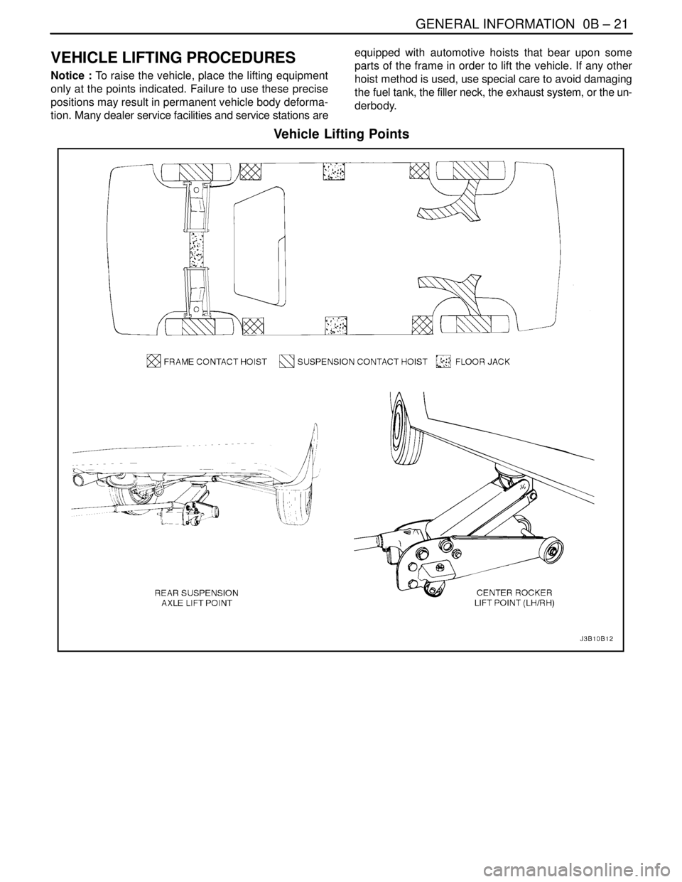
VEHICLE LIFTING PROCEDURES
Notice : To raise the vehicle, place the lifting equipment
only at the points indicated. Failure to use these precise
positions may result in permanent vehicle body deforma-
tion. Many dealer service facilities and service stations areequipped with automotive hoists that bear upon some
parts of the frame in order to lift the vehicle. If any other
hoist method is used, use special care to avoid damaging
the fuel tank, the filler neck, the exhaust system, or the un-
derbody.
Vehicle Lifting Points
Page 69 of 2643
1C1 – 26I1.4L/1.6L DOHC ENGINE MECHANICAL
DAEWOO V–121 BL4
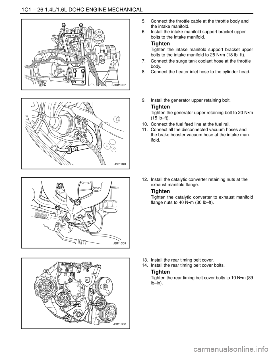
5. Connect the throttle cable at the throttle body and
the intake manifold.
6. Install the intake manifold support bracket upper
bolts to the intake manifold.
Tighten
Tighten the intake manifold support bracket upper
bolts to the intake manifold to 25 NSm (18 lb–ft).
7. Connect the surge tank coolant hose at the throttle
body.
8. Connect the heater inlet hose to the cylinder head.
9. Install the generator upper retaining bolt.
Tighten
Tighten the generator upper retaining bolt to 20 NSm
(15 lb–ft).
10. Connect the fuel feed line at the fuel rail.
11. Connect all the disconnected vacuum hoses and
the brake booster vacuum hose at the intake man-
ifold.
12. Install the catalytic converter retaining nuts at the
exhaust manifold flange.
Tighten
Tighten the catalytic converter to exhaust manifold
flange nuts to 40 NSm (30 lb–ft).
13. Install the rear timing belt cover.
14. Install the rear timing belt cover bolts.
Tighten
Tighten the rear timing belt cover bolts to 10 NSm (89
lb–in).
Page 92 of 2643

1.4L/1.6L DOHC ENGINE MECHANICAL 1C1 – 49
DAEWOO V–121 BL4
17. Disconnect the oxygen (O2) sensor connector, if
equipped.
18. Disconnect the fuel injector harness connectors.
19. Disconnect the MAT, MAP sensor connectors.
20. Disconnect the throttle position sensor (TPS) con-
nector.
21. Disconnect the generator voltage regulator connec-
tor and power lead.
22. Remove the electrical harness clamp bolt.
23. Disconnect all of the necessary vacuum lines, in-
cluding the brake booster vacuum hose.
24. Disconnect the fuel feed line at the fuel rail.
25. Disconnect the throttle cable from the throttle body
and the intake manifold bracket.
26. Disconnect the surge tank coolant hose at the
throttle body.
27. Disconnect the heater outlet hose at the coolant
pipe.
28. Disconnect the heater inlet hose from the cylinder
head.
29. Disconnect the surge tank coolant hose from the
coolant pipe.
30. Disconnect the lower radiator hose from the coolant
pipe. Disconnect the starter solenoid ”S” terminal
wire. Remove the A/C compressor, if equipped. Re-
fer to Section 7B, Manual Control Heating, Ventila-
tion, and Air Conditioning Systems.
31. Remove the catalytic converter retaining nuts from
the exhaust pipe.
32. Remove the exhaust pipe.
Page 96 of 2643
1.4L/1.6L DOHC ENGINE MECHANICAL 1C1 – 53
DAEWOO V–121 BL4
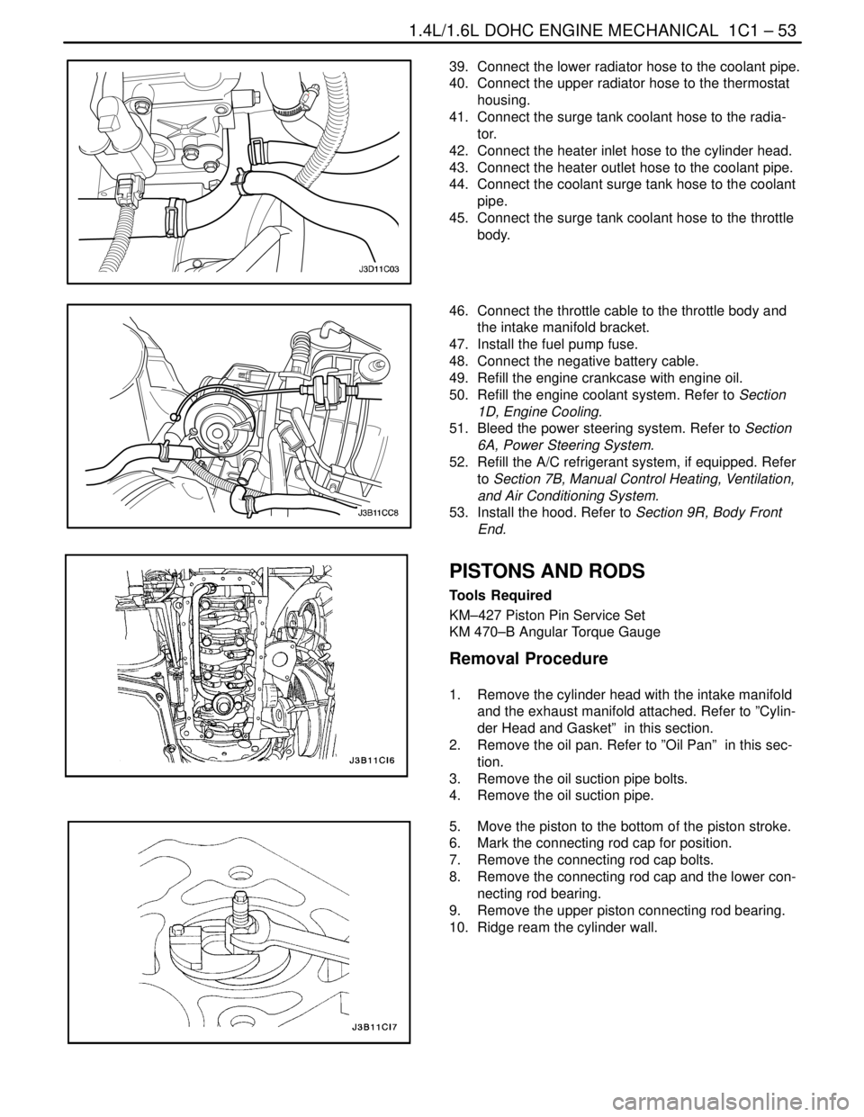
39. Connect the lower radiator hose to the coolant pipe.
40. Connect the upper radiator hose to the thermostat
housing.
41. Connect the surge tank coolant hose to the radia-
tor.
42. Connect the heater inlet hose to the cylinder head.
43. Connect the heater outlet hose to the coolant pipe.
44. Connect the coolant surge tank hose to the coolant
pipe.
45. Connect the surge tank coolant hose to the throttle
body.
46. Connect the throttle cable to the throttle body and
the intake manifold bracket.
47. Install the fuel pump fuse.
48. Connect the negative battery cable.
49. Refill the engine crankcase with engine oil.
50. Refill the engine coolant system. Refer to Section
1D, Engine Cooling.
51. Bleed the power steering system. Refer to Section
6A, Power Steering System.
52. Refill the A/C refrigerant system, if equipped. Refer
to Section 7B, Manual Control Heating, Ventilation,
and Air Conditioning System.
53. Install the hood. Refer to Section 9R, Body Front
End.
PISTONS AND RODS
Tools Required
KM–427 Piston Pin Service Set
KM 470–B Angular Torque Gauge
Removal Procedure
1. Remove the cylinder head with the intake manifold
and the exhaust manifold attached. Refer to ”Cylin-
der Head and Gasket” in this section.
2. Remove the oil pan. Refer to ”Oil Pan” in this sec-
tion.
3. Remove the oil suction pipe bolts.
4. Remove the oil suction pipe.
5. Move the piston to the bottom of the piston stroke.
6. Mark the connecting rod cap for position.
7. Remove the connecting rod cap bolts.
8. Remove the connecting rod cap and the lower con-
necting rod bearing.
9. Remove the upper piston connecting rod bearing.
10. Ridge ream the cylinder wall.
Page 136 of 2643
1C2 – 16I1.8L DOHC ENGINE MECHANICAL
DAEWOO V–121 BL4
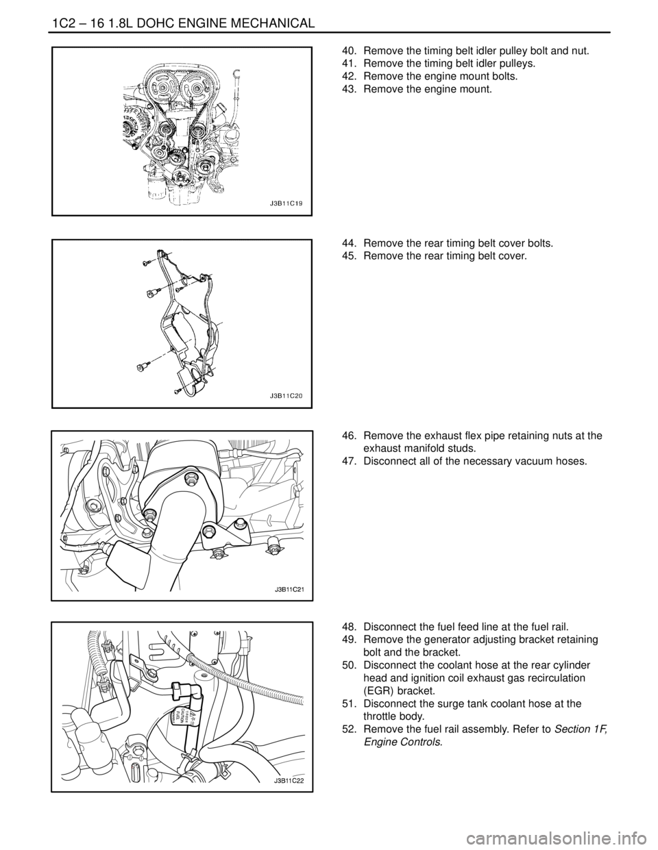
40. Remove the timing belt idler pulley bolt and nut.
41. Remove the timing belt idler pulleys.
42. Remove the engine mount bolts.
43. Remove the engine mount.
44. Remove the rear timing belt cover bolts.
45. Remove the rear timing belt cover.
46. Remove the exhaust flex pipe retaining nuts at the
exhaust manifold studs.
47. Disconnect all of the necessary vacuum hoses.
48. Disconnect the fuel feed line at the fuel rail.
49. Remove the generator adjusting bracket retaining
bolt and the bracket.
50. Disconnect the coolant hose at the rear cylinder
head and ignition coil exhaust gas recirculation
(EGR) bracket.
51. Disconnect the surge tank coolant hose at the
throttle body.
52. Remove the fuel rail assembly. Refer to Section 1F,
Engine Controls.
Page 138 of 2643
1C2 – 18I1.8L DOHC ENGINE MECHANICAL
DAEWOO V–121 BL4
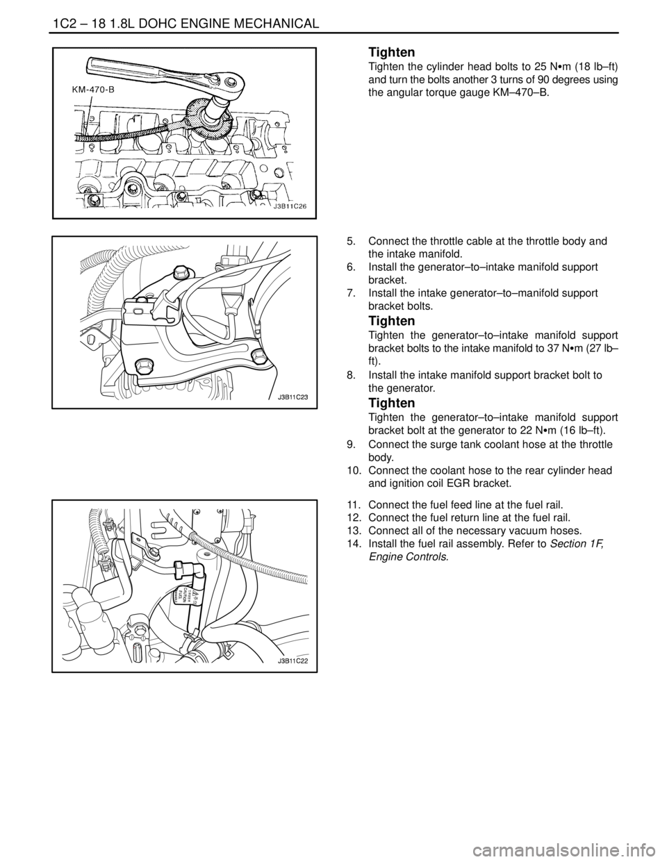
Tighten
Tighten the cylinder head bolts to 25 NSm (18 lb–ft)
and turn the bolts another 3 turns of 90 degrees using
the angular torque gauge KM–470–B.
5. Connect the throttle cable at the throttle body and
the intake manifold.
6. Install the generator–to–intake manifold support
bracket.
7. Install the intake generator–to–manifold support
bracket bolts.
Tighten
Tighten the generator–to–intake manifold support
bracket bolts to the intake manifold to 37 NSm (27 lb–
ft).
8. Install the intake manifold support bracket bolt to
the generator.
Tighten
Tighten the generator–to–intake manifold support
bracket bolt at the generator to 22 NSm (16 lb–ft).
9. Connect the surge tank coolant hose at the throttle
body.
10. Connect the coolant hose to the rear cylinder head
and ignition coil EGR bracket.
11. Connect the fuel feed line at the fuel rail.
12. Connect the fuel return line at the fuel rail.
13. Connect all of the necessary vacuum hoses.
14. Install the fuel rail assembly. Refer to Section 1F,
Engine Controls.
Page 167 of 2643

1.8L DOHC ENGINE MECHANICAL 1C2 – 47
DAEWOO V–121 BL4
19. Disconnect the oxygen (O2) sensor connector, if
equipped.
20. Disconnect the idle air control (IAC) valve connec-
tor.
21. Disconnect the throttle position sensor (TPS) con-
nector.
22. Disconnect the engine coolant temperature sensor
(CTS) connector.
23. Disconnect the CTS connector.
24. Disconnect the generator voltage regulator connec-
tor and power lead.
25. Disconnect all of the necessary vacuum lines, in-
cluding the brake booster vacuum hose.
26. Disconnect the fuel return line at the fuel rail.
27. Disconnect the fuel feed line at the fuel rail.
28. Remove the fuel rail and injector channel cover as
an assembly. Refer to Section 1F, Engine Controls.
29. Disconnect the throttle cable from the throttle body
and the intake manifold bracket.
30. Disconnect the coolant hose at the throttle body.
31. Disconnect the heater outlet hose at the coolant
pipe.
32. Disconnect the coolant bypass hose from the cylin-
der head.
33. Disconnect the surge tank coolant hose from the
coolant pipe.
34. Disconnect the lower radiator hose from the coolant
pipe.
35. Disconnect the starter solenoid ”S” terminal wire
and power lead.
36. Remove the A/C compressor. Refer to Section 7B,
Manual Control Heating, Ventilation, and Air Condi-
tioning Systems.
37. Remove the exhaust flex pipe retaining nuts from
the exhaust manifold studs.
38. Remove the exhaust flex pipe retaining nuts from
the catalytic converter or the connecting pipe.
39. Remove the exhaust flex pipe.