2004 DAEWOO LACETTI Section 9B Lighting Systems
[x] Cancel search: Section 9B Lighting SystemsPage 5 of 2643

v
TABLE OF CONTENTS
Section 0B General Information
Section 1 Engine
Section 1A General Engine Information
Section 1C1 1.4L/1.6L DOHC Engine Mechanical
Section 1C2 1.8L DOHC Engine Mechanical
Section 1D Engine Cooling
Section 1E Engine Electrical
Section 1F Engine Controls
Section 1G Engine Exhaust
Section 2 Suspension
Section 2A Suspension Diagnosis
Section 2B Wheel Alignment
Section 2C Front Suspension
Section 2D Rear Suspension
Section 2E Tires and Wheels
Section 3 Driveline/Axle
Section 3A Automatic Transaxle Drive Axle
Section 3B Manual Transaxle Drive Axle
Section 4 Brakes
Section 4A Hydraulic Brakes
Section 4B Master Cylinder
Section 4C Power Booster
Section 4D Front Disc Brakes
Section 4E1 Rear Disc Brakes
Section 4E2 Rear Drum Brakes
Section 4F Antilock Brake System
Section 4G Parking Brake
Section 5 Transmission/Transaxle
Section 5A1 ZF 4HP16 Automatic Transaxle
Section 5A2 AISIN Automatic Transaxle
Section 5B Five-Speed Manual Transaxle
Section 5C Clutch
Section 6 Steering
Section 6A Power Steering System
Section 6B Power Steering PumpSection 6C Power Steering Gear
Section 6E Steering Wheel and Column
Section 7 Heating, Ventilation, and Air
Conditioning (HVAC)
Section 7A Heating and Ventilation System
Section 7B Manual Control Heating, Ventilation,
and Air Conditioning System
Section 7D Automatic Temperature Control HVAC
Section 8 Restraints
Section 8A Seat Belts
Section 8B Supplemental Inflatable Restraints
(SIR)
Section 9 Body and Accessories
Section 9A Body Wiring System
Section 9B Lighting Systems
Section 9C Horns
Section 9D Wipers/Washer Systems
Section 9E Instrumentation/Driver Information
Section 9F Audio Systems
Section 9G Interior Trim
Section 9H Seats
Section 9I Waterleaks
Section 9J Windnoise
Section 9K Squeaks and Rattles
Section 9L Glass and Mirrors
Section 9M Exterior Trim
Section 9N Frame and Underbody
Section 9O Bumpers and Fascias
Section 9P Doors
Section 9Q Roof
Section 9R Body Front End
Section 9S Body Rear End
Section 9T1 Remote Keyless Entry and Anti–Theft
System
Section 9T2 Immobilizer Anti–Theft System
Page 1975 of 2643

SECTION : 7A
HEATING AND VENTILATION SYSTEM
CAUTION : Disconnect the negative battery cable before removing or installing any electrical unit or when a tool
or equipment could easily come in contact with exposed electrical terminals. Disconnecting this cable will help
prevent personal injury and damage to the vehicle. The ignition must also be in LOCK unless otherwise noted.
TABLE OF CONTENTS
SPECIFICATIONS7A–1 . . . . . . . . . . . . . . . . . . . . . . . . . .
Heater Temperature Specifications 7A–1. . . . . . . . . . .
Fastener Tightening Specifications 7A–1. . . . . . . . . . .
SCHEMATIC AND ROUTING DIAGRAMS7A–3 . . . . .
Non–A/C Diagrams 7A–3. . . . . . . . . . . . . . . . . . . . . . . .
Airflow – Typical 7A–4. . . . . . . . . . . . . . . . . . . . . . . . . . .
Airflow with Rear Heating Duct 7A–5. . . . . . . . . . . . . .
DIAGNOSIS7A–6 . . . . . . . . . . . . . . . . . . . . . . . . . . . . . . . .
HEATER SYSTEM 7A–6. . . . . . . . . . . . . . . . . . . . . . . . . .
Insufficient Heating or Defrosting 7A–6. . . . . . . . . . . . .
Blower Electrical 7A–9. . . . . . . . . . . . . . . . . . . . . . . . . . .
Improper Air delivery or No Mode Shift 7A–11. . . . . .
Too Much Heat 7A–13. . . . . . . . . . . . . . . . . . . . . . . . . . .
Controls 7A–15. . . . . . . . . . . . . . . . . . . . . . . . . . . . . . . . .
Blower Noise 7A–16. . . . . . . . . . . . . . . . . . . . . . . . . . . . . MAINTENANCE AND REPAIR7A–18 . . . . . . . . . . . . . .
ON–VEHICLE SERVICE 7A–18. . . . . . . . . . . . . . . . . . . .
Temperature Cable Adjustment 7A–18. . . . . . . . . . . . .
Temperature Control Cable 7A–18. . . . . . . . . . . . . . . . .
Control Assembly 7A–20. . . . . . . . . . . . . . . . . . . . . . . . .
Control Assembly Knob Lighting 7A–21. . . . . . . . . . . .
Heater/Air Distributor Case Assembly 7A–21. . . . . . .
Blower Motor 7A–23. . . . . . . . . . . . . . . . . . . . . . . . . . . . .
High–Blower Relay 7A–24. . . . . . . . . . . . . . . . . . . . . . . .
Blower Resistor 7A–25. . . . . . . . . . . . . . . . . . . . . . . . . .
Heater Hoses 7A–25. . . . . . . . . . . . . . . . . . . . . . . . . . . .
Heater Core 7A–26. . . . . . . . . . . . . . . . . . . . . . . . . . . . . .
GENERAL DESCRIPTION AND SYSTEM
OPERATION7A–28 . . . . . . . . . . . . . . . . . . . . . . . . . . . . .
Heating and Ventilation Systems 7A–28. . . . . . . . . . . .
SPECIFICATIONS
HEATER TEMPERATURE SPECIFICATIONS
Ambient Air TemperatureHeater Outlet Air Temperature
–18°C (0°F)54°C (129°F)
– 4°C (25°F)59°C (138°F)
10°C (50°F)64°C (147°F)
24°C (75°F)68°C (154°F)
FASTENER TIGHTENING SPECIFICATIONS
ApplicationNSmLb–FtLb–In
Blower Motor–to–A/C Assembly Screws1.2–11
Blower Motor Resistor Screws1.2–11
Blower Motor Retaining Screws1.2–11
Controller Retaining Screws2–18
Heater/Air Distributor Case Assembly Screw4–35
Page 2025 of 2643

MANUAL CONTROL HEATING, VENTILATION AND AIR CONDITIONING SYSTEM 7B – 23
DAEWOO V–121 BL4
SERVICEABLE COMPONENTS
COMPONENTS USED IN NON–A/C
SYSTEMS
Refer to Section 7A, Heating and Ventilation System for
on–vehicle service procedures for the following sections:
S Blower Motor.
S Blower Resistor.
S Control Assembly Knob Lighting.
S Control Assembly.
S Heater Hoses.
S High–Blower Relay.
S A/C Control Vacuum Tank.
S Temperature Control Cable.
S Heater/Air Distributor Case Assembly (A/C Mod-
ule).
S Heater Core
Page 2028 of 2643

7B – 26IMANUAL CONTROL HEATING, VENTILATION AND AIR CONDITIONING SYSTEM
DAEWOO V–121 BL4
Installation Procedure
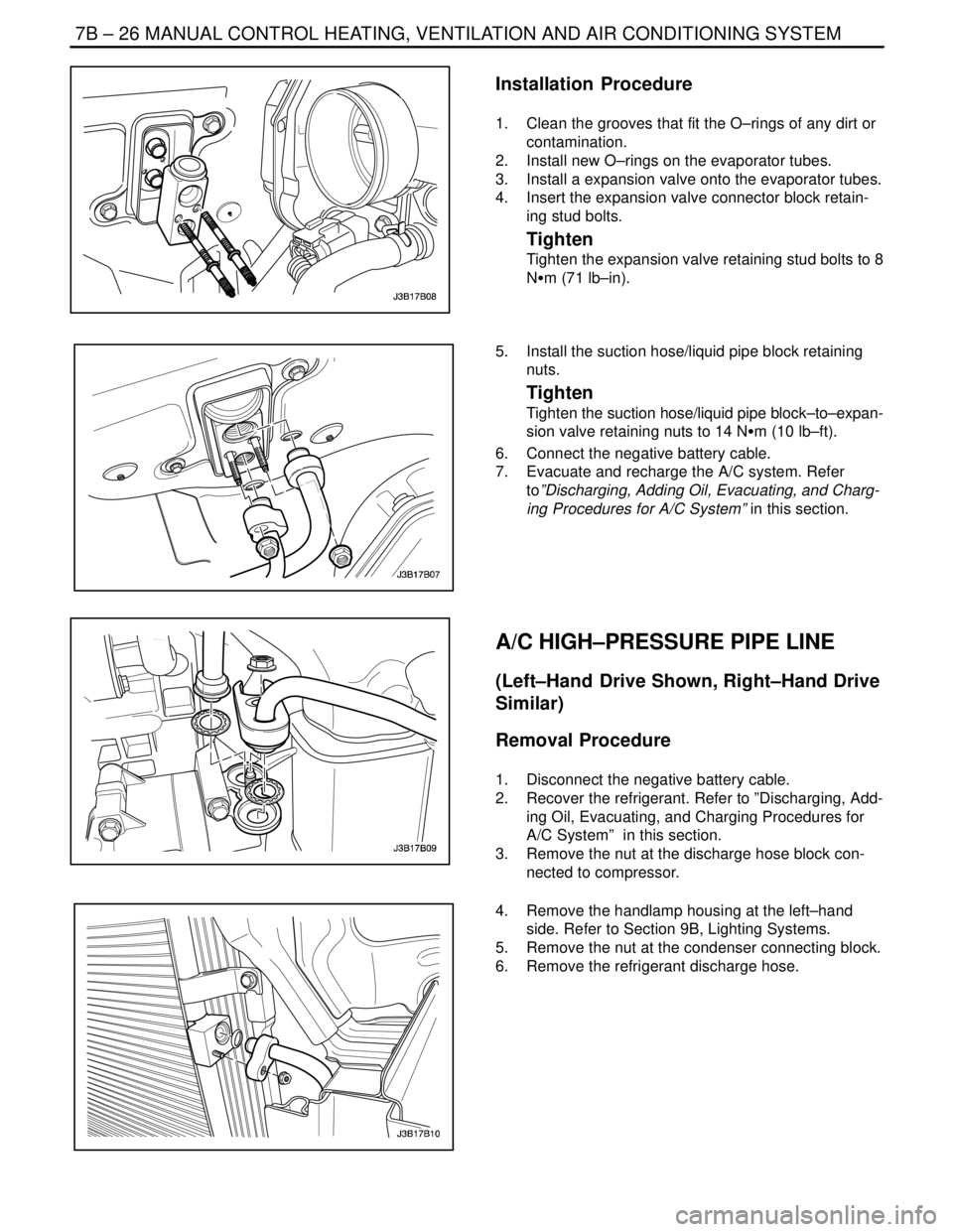
1. Clean the grooves that fit the O–rings of any dirt or
contamination.
2. Install new O–rings on the evaporator tubes.
3. Install a expansion valve onto the evaporator tubes.
4. Insert the expansion valve connector block retain-
ing stud bolts.
Tighten
Tighten the expansion valve retaining stud bolts to 8
NSm (71 lb–in).
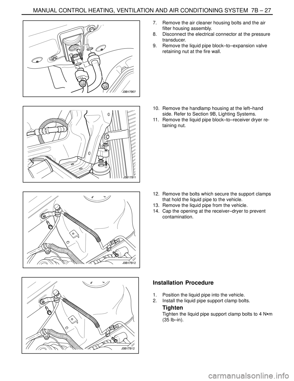
5. Install the suction hose/liquid pipe block retaining
nuts.
Tighten
Tighten the suction hose/liquid pipe block–to–expan-
sion valve retaining nuts to 14 NSm (10 lb–ft).
6. Connect the negative battery cable.
7. Evacuate and recharge the A/C system. Refer
to”Discharging, Adding Oil, Evacuating, and Charg-
ing Procedures for A/C System” in this section.
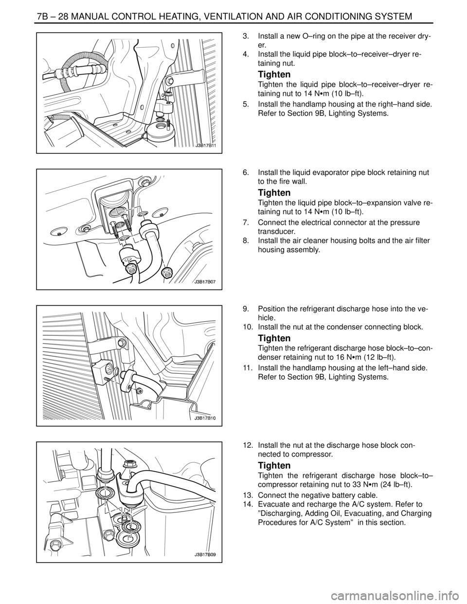
A/C HIGH–PRESSURE PIPE LINE
(Left–Hand Drive Shown, Right–Hand Drive
Similar)
Removal Procedure
1. Disconnect the negative battery cable.
2. Recover the refrigerant. Refer to ”Discharging, Add-
ing Oil, Evacuating, and Charging Procedures for
A/C System” in this section.
3. Remove the nut at the discharge hose block con-
nected to compressor.
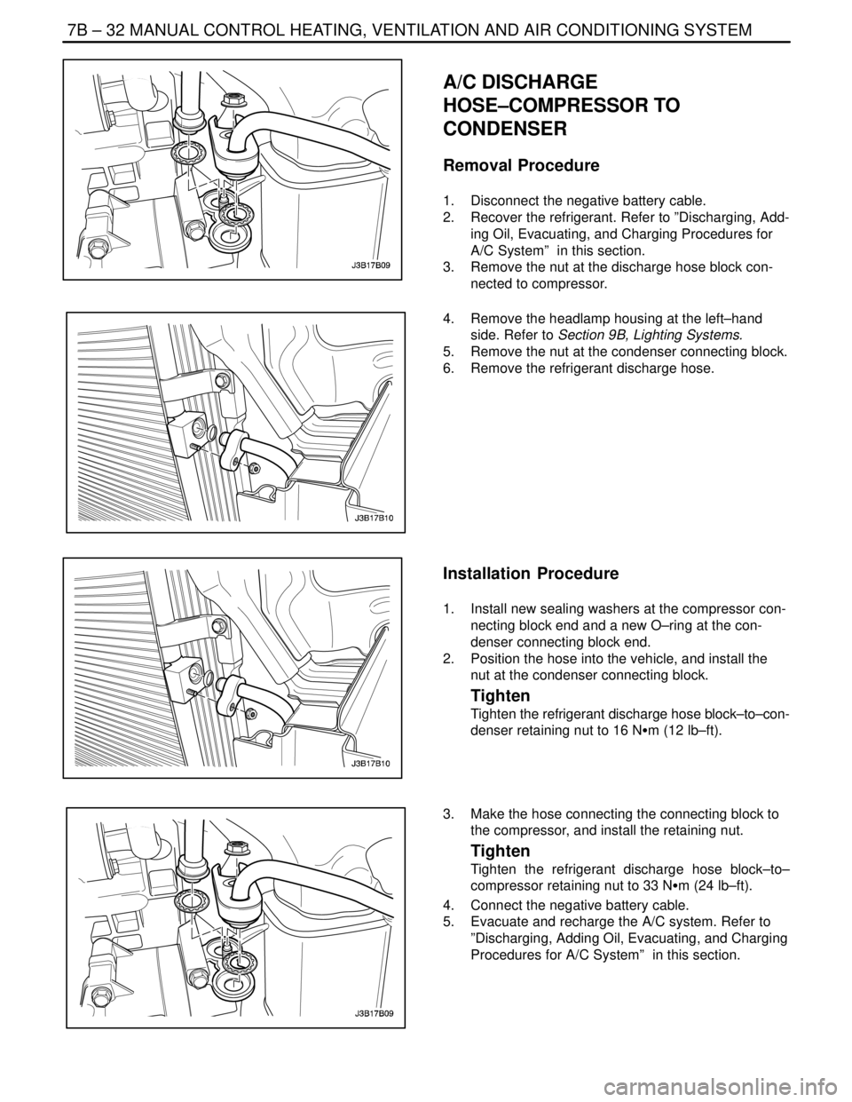
4. Remove the handlamp housing at the left–hand
side. Refer to Section 9B, Lighting Systems.
5. Remove the nut at the condenser connecting block.
6. Remove the refrigerant discharge hose.
Page 2029 of 2643

MANUAL CONTROL HEATING, VENTILATION AND AIR CONDITIONING SYSTEM 7B – 27
DAEWOO V–121 BL4
7. Remove the air cleaner housing bolts and the air
filter housing assembly.
8. Disconnect the electrical connector at the pressure
transducer.
9. Remove the liquid pipe block–to–expansion valve
retaining nut at the fire wall.
10. Remove the handlamp housing at the left–hand
side. Refer to Section 9B, Lighting Systems.
11. Remove the liquid pipe block–to–receiver dryer re-
taining nut.
12. Remove the bolts which secure the support clamps
that hold the liquid pipe to the vehicle.
13. Remove the liquid pipe from the vehicle.
14. Cap the opening at the receiver–dryer to prevent
contamination.
Installation Procedure
1. Position the liquid pipe into the vehicle.
2. Install the liquid pipe support clamp bolts.
Tighten
Tighten the liquid pipe support clamp bolts to 4 NSm
(35 lb–in).
Page 2030 of 2643

7B – 28IMANUAL CONTROL HEATING, VENTILATION AND AIR CONDITIONING SYSTEM
DAEWOO V–121 BL4
3. Install a new O–ring on the pipe at the receiver dry-
er.
4. Install the liquid pipe block–to–receiver–dryer re-
taining nut.
Tighten
Tighten the liquid pipe block–to–receiver–dryer re-
taining nut to 14 NSm (10 lb–ft).
5. Install the handlamp housing at the right–hand side.
Refer to Section 9B, Lighting Systems.
6. Install the liquid evaporator pipe block retaining nut
to the fire wall.
Tighten
Tighten the liquid pipe block–to–expansion valve re-
taining nut to 14 NSm (10 lb–ft).
7. Connect the electrical connector at the pressure
transducer.
8. Install the air cleaner housing bolts and the air filter
housing assembly.
9. Position the refrigerant discharge hose into the ve-
hicle.
10. Install the nut at the condenser connecting block.
Tighten
Tighten the refrigerant discharge hose block–to–con-
denser retaining nut to 16 NSm (12 lb–ft).
11. Install the handlamp housing at the left–hand side.
Refer to Section 9B, Lighting Systems.
12. Install the nut at the discharge hose block con-
nected to compressor.
Tighten
Tighten the refrigerant discharge hose block–to–
compressor retaining nut to 33 NSm (24 lb–ft).
13. Connect the negative battery cable.
14. Evacuate and recharge the A/C system. Refer to
”Discharging, Adding Oil, Evacuating, and Charging
Procedures for A/C System” in this section.
Page 2034 of 2643

7B – 32IMANUAL CONTROL HEATING, VENTILATION AND AIR CONDITIONING SYSTEM
DAEWOO V–121 BL4
A/C DISCHARGE
HOSE–COMPRESSOR TO
CONDENSER
Removal Procedure
1. Disconnect the negative battery cable.
2. Recover the refrigerant. Refer to ”Discharging, Add-
ing Oil, Evacuating, and Charging Procedures for
A/C System” in this section.
3. Remove the nut at the discharge hose block con-
nected to compressor.
4. Remove the headlamp housing at the left–hand
side. Refer to Section 9B, Lighting Systems.
5. Remove the nut at the condenser connecting block.
6. Remove the refrigerant discharge hose.
Installation Procedure
1. Install new sealing washers at the compressor con-
necting block end and a new O–ring at the con-
denser connecting block end.
2. Position the hose into the vehicle, and install the
nut at the condenser connecting block.
Tighten
Tighten the refrigerant discharge hose block–to–con-
denser retaining nut to 16 NSm (12 lb–ft).
3. Make the hose connecting the connecting block to
the compressor, and install the retaining nut.
Tighten
Tighten the refrigerant discharge hose block–to–
compressor retaining nut to 33 NSm (24 lb–ft).
4. Connect the negative battery cable.
5. Evacuate and recharge the A/C system. Refer to
”Discharging, Adding Oil, Evacuating, and Charging
Procedures for A/C System” in this section.
Page 2227 of 2643

SECTION : 9B
LIGHTING SYSTEMS
CAUTION : Disconnect the negative battery cable before removing or installing any electrical unit or when a tool
or equipment could easily come in contact with exposed electrical terminals. Disconnecting this cable will help
prevent personal injury and damage to the vehicle. The ignition must also be in LOCK unless otherwise noted.
TABLE OF CONTENTS
SPECIFICATIONS9B–2 . . . . . . . . . . . . . . . . . . . . . . . . . .
Bulb Usage Chart 9B–2. . . . . . . . . . . . . . . . . . . . . . . . . .
Fastener Tightening Specifications 9B–2. . . . . . . . . . .
SCHEMATIC AND ROUTING DIAGRAMS9B–3 . . . . .
Backup Lamps Circuit 9B–3. . . . . . . . . . . . . . . . . . . . . .
Instruments Circuit (W/O Dimmer Control :
General Only) 9B–4. . . . . . . . . . . . . . . . . . . . . . . . . . .
Instruments Circuit (W/ Dimmer Control) 9B–5. . . . . .
Front And Rear Fog Lamps Circuit 9B–6. . . . . . . . . . .
Headlamps–On Reminder Chime Circuit 9B–7. . . . . .
Headlamps and Headlamp Leveling Circuit 9B–8. . . .
Daytime Running Lamps Circuit 9B–9. . . . . . . . . . . . .
Parking, Tail and License Lamps Circuit 9B–10. . . . . .
Stoplamps Circuit 9B–11. . . . . . . . . . . . . . . . . . . . . . . . .
Turn and Hazard Lamps Circuit 9B–12. . . . . . . . . . . . .
Interior Courtesy and Luggage Compartment Lamp
Circuit 9B–13. . . . . . . . . . . . . . . . . . . . . . . . . . . . . . . . .
DIAGNOSIS9B–14 . . . . . . . . . . . . . . . . . . . . . . . . . . . . . . .
Headlamps–On Reminder Chime 9B–14. . . . . . . . . . .
Headlamps 9B–16. . . . . . . . . . . . . . . . . . . . . . . . . . . . . .
Headlamp Leveling 9B–20. . . . . . . . . . . . . . . . . . . . . . .
Daytime Running Lamps 9B–22. . . . . . . . . . . . . . . . . . .
Parking Lamps and Taillamps 9B–23. . . . . . . . . . . . . .
Interior Courtesy and Luggage Compartment
Lamps 9B–31. . . . . . . . . . . . . . . . . . . . . . . . . . . . . . . . .
Fog Lamps 9B–34. . . . . . . . . . . . . . . . . . . . . . . . . . . . . .
MAINTENANCE AND REPAIR9B–36 . . . . . . . . . . . . . .
ON–VEHICLE SERVICE 9B–36. . . . . . . . . . . . . . . . . . . . Headlamps/Front Turn Signal Lamps 9B–36. . . . . . . .
Daytime Running Lamp Module 9B–37. . . . . . . . . . . . .
Parking Lamps 9B–37. . . . . . . . . . . . . . . . . . . . . . . . . . .
Side Turn Signal Lamps 9B–38. . . . . . . . . . . . . . . . . . .
Front Fog Lamps 9B–38. . . . . . . . . . . . . . . . . . . . . . . . .
Notchback Rear Combination Lamps 9B–39. . . . . . . .
Hatchback Rear Combination Lamps 9B–40. . . . . . . .
Hatchback Extension Lamps 9B–40. . . . . . . . . . . . . . .
Notchback Center High–Mounted Stoplamp 9B–41. .
Hatchback Center High–Mounted Stoplamp 9B–41. .
License Plate Lamps 9B–42. . . . . . . . . . . . . . . . . . . . . .
Door Jamb Switch 9B–42. . . . . . . . . . . . . . . . . . . . . . . .
Center Room Lamp 9B–43. . . . . . . . . . . . . . . . . . . . . . .
Map Lamp 9B–43. . . . . . . . . . . . . . . . . . . . . . . . . . . . . . .
Luggage Compartment Lamp 9B–44. . . . . . . . . . . . . . .
Ashtray and Cigar Lighter Lamp 9B–44. . . . . . . . . . . .
GENERAL DESCRIPTION AND SYSTEM
OPERATION9B–46 . . . . . . . . . . . . . . . . . . . . . . . . . . . . .
Headlamps–On Reminder Chime 9B–46. . . . . . . . . . .
Headlamps 9B–46. . . . . . . . . . . . . . . . . . . . . . . . . . . . . .
Daytime Running Lamps 9B–46. . . . . . . . . . . . . . . . . . .
Parking and Turn Signal Lamps 9B–46. . . . . . . . . . . . .
Fog Lamps 9B–46. . . . . . . . . . . . . . . . . . . . . . . . . . . . . .
Rear Combination Lamps 9B–46. . . . . . . . . . . . . . . . . .
License Plate Lamp 9B–46. . . . . . . . . . . . . . . . . . . . . . .
Interior Courtesy Lamp 9B–46. . . . . . . . . . . . . . . . . . . .
Luggage Compartment Lamp 9B–46. . . . . . . . . . . . . . .
Backup Lamps 9B–47. . . . . . . . . . . . . . . . . . . . . . . . . . .