2004 DAEWOO LACETTI light
[x] Cancel search: lightPage 2384 of 2643

GLASS AND MIRRORS 9L – 5
DAEWOO V–121 BL4
DIAGNOSIS
TESTING REAR WINDOW
DEFOGGER GRID LINE
If it has been observed during use that a grid line is inop-
erative, the following procedure can be used to find the
break. If none of the grid lines is operating, a full system
diagnosis should be completed before attempting to repair
the grid lines.
1. Turn the ignition ON.
2. Turn the rear window defogger on.
3. From the inside of the vehicle, connect a voltmeter
to each end of a grid line. The voltmeter will indi-
cate battery voltage if the grid line is open.
Notice : Use care when touching the voltmeter leads to a
grid line. If the leads are roughly applied, the grid line may
be scratched, resulting in an open circuit.4. If a grid line is found to be open, move a voltmeter
lead from one side of the grid line and retest at a
point nearer to the other side of the window. Contin-
ue to retest, each time bringing one of the voltmeter
leads closer to the opposite side of the window
from where it was originally placed. The break in
the grid line is at the point where the voltmeter be-
gins reading 0 volts instead of battery voltage.
5. Use a marking crayon to lightly mark the break
point on the rear window. Mark the glass instead of
marking directly on the grid line, and make the
mark far enough from the grid line so that it can
easily be removed without disturbing the repair.
6. Use a grid line repair kit to fix the break in the grid
line. Refer to ”Rear Window Defogger Grid Line
Repair” in this section.
OUTSIDE REARVIEW MIRROR DEFOGGERS
StepActionValue(s)YesNo
1Check the rear window defogger.
Does the rear window defogger work?–Go to Step 4 Go to Step 2
2Repair the rear window defogger before proceeding
with the outside rearview mirror diagnosis.
Is the repair complete?–Go to Step 3–
3Test the outside rearview mirror defoggers.
Does the repair of the rear window defogger system
also fix the problem with the outside rearview mirror
defoggers?–System OKGo to Step 4
4Check fuse Ef25.
Is fuse Ef25 blown?–Go to Step 5 Go to Step 6
51. Check for a short circuit and repair it, if neces-
sary.
2. Replace the fuse.
Is the repair complete?–System OK–
61. On the side of the vehicle which has the mal-
functioning outside rearview mirror defogger,
remove the black plastic escutcheon from the
trim panel side of the door.
2. Disconnect the outside rearview mirror electri-
cal connector.
3. Turn the ignition ON.
4. Turn on the defogger.
5. Use a voltmeter to backprobe terminal 3 (ORN)
at the outside rearview mirror electrical connec-
tor.
Does the voltmeter indicate the specified value?11–14 v Go to Step 8 Go to Step 7
7Repair the open circuit between fuse Ef25 and the
outside rearview mirror connector.
Is the repair complete?–System OK–
Page 2413 of 2643
9O – 2IBUMPERS AND FASCIAS
DAEWOO V–121 BL4
MAINTENANCE AND REPAIR
ON–VEHICLE SERVICE
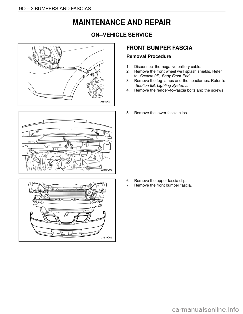
FRONT BUMPER FASCIA
Removal Procedure
1. Disconnect the negative battery cable.
2. Remove the front wheel well splash shields. Refer
to Section 9R, Body Front End.
3. Remove the fog lamps and the headlamps. Refer to
Section 9B, Lighting Systems.
4. Remove the fender–to–fascia bolts and the screws.
5. Remove the lower fascia clips.
6. Remove the upper fascia clips.
7. Remove the front bumper fascia.
Page 2414 of 2643
BUMPERS AND FASCIAS 9O – 3
DAEWOO V–121 BL4
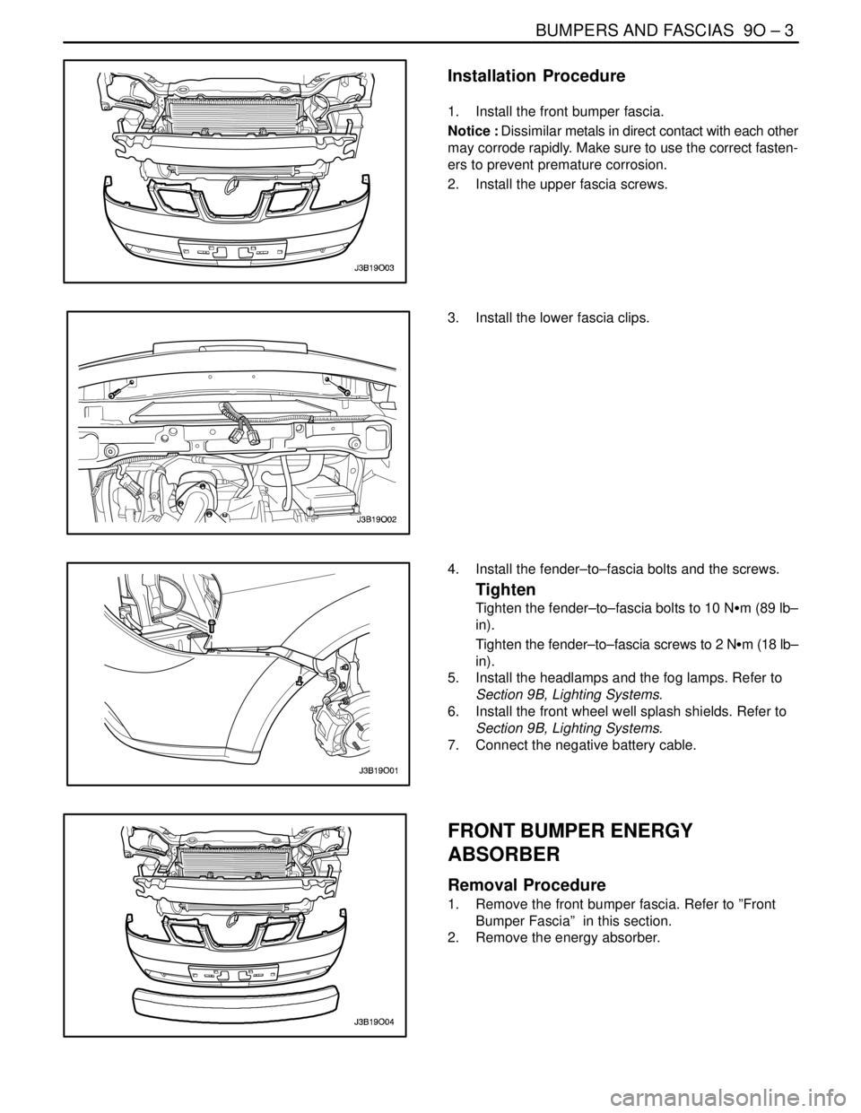
Installation Procedure
1. Install the front bumper fascia.
Notice : Dissimilar metals in direct contact with each other
may corrode rapidly. Make sure to use the correct fasten-
ers to prevent premature corrosion.
2. Install the upper fascia screws.
3. Install the lower fascia clips.
4. Install the fender–to–fascia bolts and the screws.
Tighten
Tighten the fender–to–fascia bolts to 10 NSm (89 lb–
in).
Tighten the fender–to–fascia screws to 2 NSm (18 lb–
in).
5. Install the headlamps and the fog lamps. Refer to
Section 9B, Lighting Systems.
6. Install the front wheel well splash shields. Refer to
Section 9B, Lighting Systems.
7. Connect the negative battery cable.
FRONT BUMPER ENERGY
ABSORBER
Removal Procedure
1. Remove the front bumper fascia. Refer to ”Front
Bumper Fascia” in this section.
2. Remove the energy absorber.
Page 2442 of 2643
9P – 22IDOORS
DAEWOO V–121 BL4
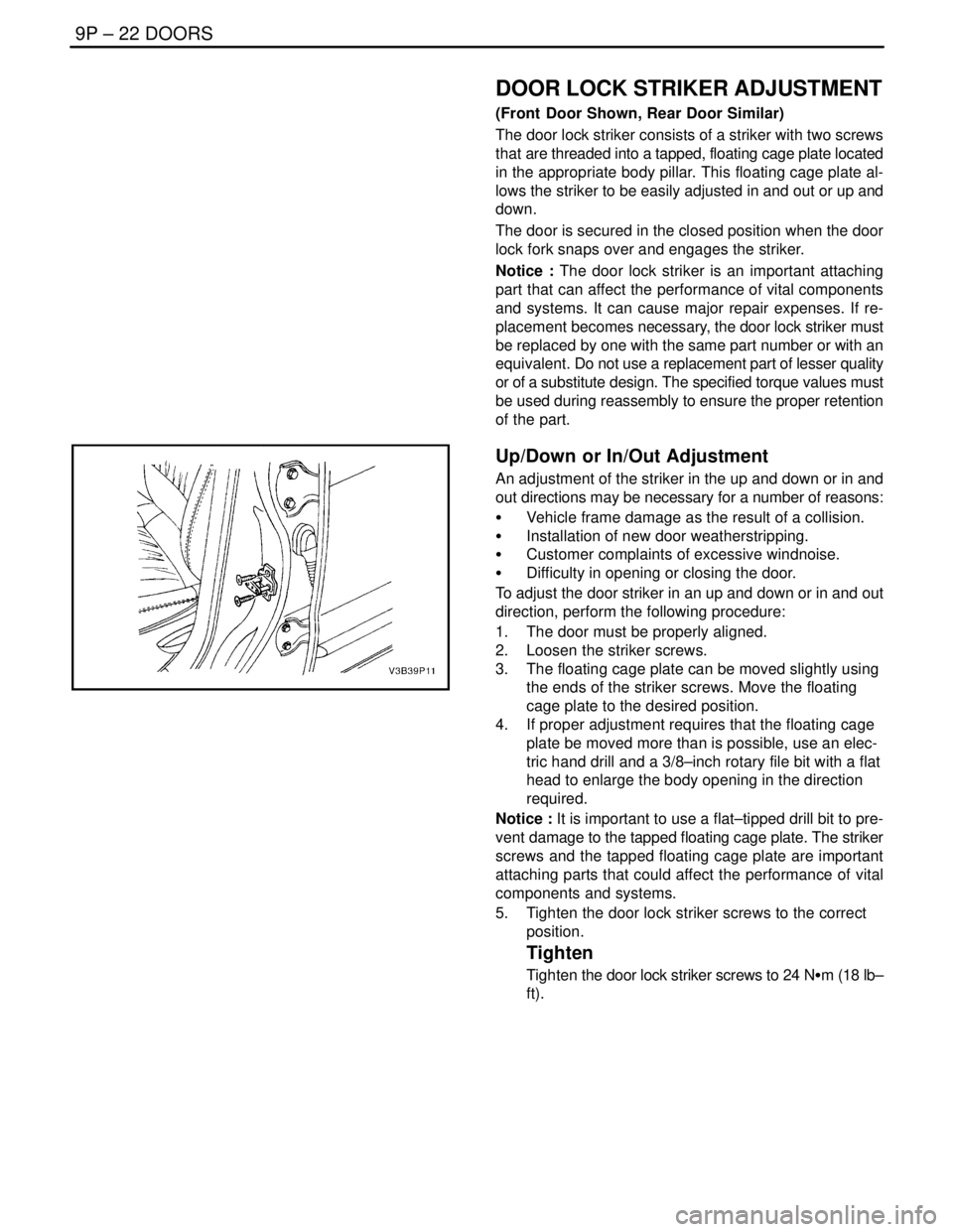
DOOR LOCK STRIKER ADJUSTMENT
(Front Door Shown, Rear Door Similar)
The door lock striker consists of a striker with two screws
that are threaded into a tapped, floating cage plate located
in the appropriate body pillar. This floating cage plate al-
lows the striker to be easily adjusted in and out or up and
down.
The door is secured in the closed position when the door
lock fork snaps over and engages the striker.
Notice : The door lock striker is an important attaching
part that can affect the performance of vital components
and systems. It can cause major repair expenses. If re-
placement becomes necessary, the door lock striker must
be replaced by one with the same part number or with an
equivalent. Do not use a replacement part of lesser quality
or of a substitute design. The specified torque values must
be used during reassembly to ensure the proper retention
of the part.
Up/Down or In/Out Adjustment
An adjustment of the striker in the up and down or in and
out directions may be necessary for a number of reasons:
S Vehicle frame damage as the result of a collision.
S Installation of new door weatherstripping.
S Customer complaints of excessive windnoise.
S Difficulty in opening or closing the door.
To adjust the door striker in an up and down or in and out
direction, perform the following procedure:
1. The door must be properly aligned.
2. Loosen the striker screws.
3. The floating cage plate can be moved slightly using
the ends of the striker screws. Move the floating
cage plate to the desired position.
4. If proper adjustment requires that the floating cage
plate be moved more than is possible, use an elec-
tric hand drill and a 3/8–inch rotary file bit with a flat
head to enlarge the body opening in the direction
required.
Notice : It is important to use a flat–tipped drill bit to pre-
vent damage to the tapped floating cage plate. The striker
screws and the tapped floating cage plate are important
attaching parts that could affect the performance of vital
components and systems.
5. Tighten the door lock striker screws to the correct
position.
Tighten
Tighten the door lock striker screws to 24 NSm (18 lb–
ft).
Page 2447 of 2643
DOORS 9P – 27
DAEWOO V–121 BL4
Installation Procedure
1. Connect the electrical connector and the body–to-
door rubber grommet.
Notice : Dissimilar metals in direct contact with each other
may corrode rapidly. Make sure to use the correct fasten-
ers to prevent premature corrosion.
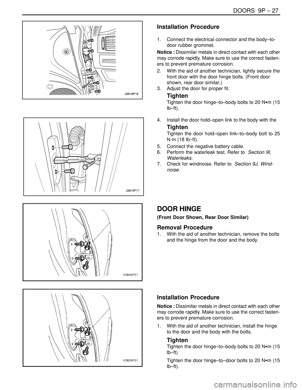
2. With the aid of another technician, lightly secure the
front door with the door hinge bolts. (Front door
shown, rear door similar.)
3. Adjust the door for proper fit.
Tighten
Tighten the door hinge–to–body bolts to 20 NSm (15
lb–ft).
4. Install the door hold–open link to the body with the
Tighten
Tighten the door hold–open link–to–body bolt to 25
N·m (18 lb–ft).
5. Connect the negative battery cable.
6. Perform the waterleak test. Refer to Section 9I,
Waterleaks.
7. Check for windnoise. Refer to Section 9J, Wind-
noise.
DOOR HINGE
(Front Door Shown, Rear Door Similar)
Removal Procedure
1. With the aid of another technician, remove the bolts
and the hinge from the door and the body.
Installation Procedure
Notice : Dissimilar metals in direct contact with each other
may corrode rapidly. Make sure to use the correct fasten-
ers to prevent premature corrosion.
1. With the aid of another technician, install the hinge
to the door and the body with the bolts.
Tighten
Tighten the door hinge–to–body bolts to 20 NSm (15
lb–ft)
Tighten the door hinge–to–door bolts to 20 NSm (15
lb–ft).
Page 2459 of 2643
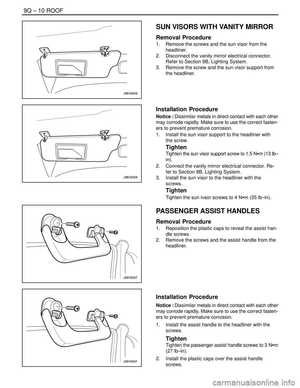
9Q – 10IROOF
DAEWOO V–121 BL4
SUN VISORS WITH VANITY MIRROR
Removal Procedure
1. Remove the screws and the sun visor from the
headliner.
2. Disconnect the vanity mirror electrical connector.
Refer to Section 9B, Lighting System.
3. Remove the screw and the sun visor support from
the headliner.
Installation Procedure
Notice : Dissimilar metals in direct contact with each other
may corrode rapidly. Make sure to use the correct fasten-
ers to prevent premature corrosion.
1. Install the sun visor support to the headliner with
the screw.
Tighten
Tighten the sun visor support screw to 1.5 NSm (13 lb–
in).
2. Connect the vanity mirror electrical connector. Re-
fer to Section 9B, Lighting System.
3. Install the sun visor to the headliner with the
screws.
Tighten
Tighten the sun ivsor screws to 4 NSm (35 lb–in).
PASSENGER ASSIST HANDLES
Removal Procedure
1. Reposition the plastic caps to reveal the assist han-
dle screws.
2. Remove the screws and the assist handle from the
headliner.
Installation Procedure
Notice : Dissimilar metals in direct contact with each other
may corrode rapidly. Make sure to use the correct fasten-
ers to prevent premature corrosion.
1. Install the assist handle to the headliner with the
screws.
Tighten
Tighten the passenger assist handle screws to 3 NSm
(27 lb–in).
2. Install the plastic caps over the assist handle
screws.
Page 2461 of 2643

9Q – 12IROOF
DAEWOO V–121 BL4
GENERAL DESCRIPTION
AND SYSTEM OPERATION
ROOF
The roof is a one–piece painted metal unit which incorpo-
rates a single solid headliner. There are two moldings, one
per side on the vehicle’s roof, which enclose and hide the
roof rail seams. The roof moldings are serviceable as indi-
vidual units.
The one–piece formed headliner consists of a molded
substrate covered with a foam–backed cloth facing. The
one–piece construction requires that the headliner be ser-
viced as a complete assembly.
POWER SUNROOF/SUNROOF
CONTROL SWITCH
The sunroof has the following characteristics:
S Intended to provide light and air through the roof
the vehicle.
S Built into the roof.
S Made of glass.
S Equipped with a sunshade that opens and closes
manually.
S Powered by an electric motor.
S Controlled by a toggle switch built into the interior
courtesy lamp assembly.
The sunroof control switch is a toggle button located on the
right side of the interior courtesy lamp assembly.
To operate the sunroof, the ignition must be ON.Tilting the Sunroof, Open and Closed
To tilt open the rear end of the sunroof, press and hold the
forward portion of the toggle button until the sunroof tilts
open.
To close the sunroof from a tilted–open position, press and
hold the rear portion of the toggle button until the sunroof
tilts closed.
Sliding the Sunroof, Open and Closed
To slide open the sunroof, press the rear portion of the
toggle button until the sunroof slides. If the sun shade is
closed, the sunroof will pull the sunshade open when the
sunroof slides open.
To close the sunroof from a slid–open position, press the
forward portion of the toggle button until the sunroof slides
closed.
SUN VISORS WITH VANITY MIRROR
The sun visors swing down in order to block out glare.
They also swing to the side when they are released from
the support. To replace the vanity mirror lamp, refer to
Section 9B, Lighting Systems.
PASSENGER ASSIST HANDLES
There is a passenger assist handle for each rear outboard
seat and for the front passenger seat. Passengers can use
these handles to assist in keeping their balance over rough
roads or during sharp turns.
COAT HOOKS
The coat hooks are located on the left and the right rear
passenger assist handles.
Page 2488 of 2643

REMOTE KEYLESS ENTRY AND ANTI–THEFT SYSTEM 9T1 – 7
DAEWOO V–121 BL4
REMOTE KEYLESS ENTRY
TRANSMITTER PROGRAMMING
The Remote Keyless Entry System allows for the use of
as many as four(4) transmitters for each vehicle. Replace-
ment Remote Keyless Entry System Transmitters must
first be programmend to specific vehicle using the
Scan100 Secan tool.
This process is completed using serial data communica-
tion between the Scan 100 Scan tool and the Remote Key-
less Entry Control Unit and is the only method available for
programming Transmitters.
Notice : All Transmitters for a specific vehicle must be pro-
grammed at same time.
Notice : Once the programming function of the Remote
Keyless Entry System is activated, any Transmitter(exist-
ing or new) that is not programmed(or reprogrammed)
during the programming procedure will no longer operate
the Remote Keyless Entry System of that vehicle.
Notice : Ensure that the doors, hood and trunk/rear hatch
are closed prior to starting the programming procedure.
1. Connect the Scan 100 Scan Tool to the Data Link
Connector(DLC)
2. Turn the Scan 100 Scan Tool ”ON” by pressing the
”Power” Button, then wait for the MAIN MENU
screen to be displayed.
3. From the MAIN MENU screen, select ”Diagnostics”
by pressing #1 on the Key Pad.
4. From the MODEL YEAR screen, select the ap-
propriate model year of the specific vehicle by ei-
ther scrolling down to the year and pressing ”EN-
TER”, or by pressing the respective item number on
the Key Pad.
5. From the VEHICLE TYPE screen, select the specif-
ic vehicle model by either scrolling down to the
model name and pressing ”ENTER”, or by pressing
the respective item number on the Key Pad.
6. From the SYSTEM SELECTION MENU screen,
select ”Body” by pressing #2 on the Key Pad.
7. From the BODY SELECTION MENU screen, select
”Coding” by pressing #2 on the Key Pad.8. From the CODY SELECTION MENU screen, select
”Coding” by pressing #1 on the Key Pad.
9. From the SECRET NUMBER OF CODINGS
screen, enter for(4) zero’s (0–0–0–0) in the for(4)
boxes labeled ”1–2–3–4–”.
10. From the CODING SYSTEM SELECT screen, se-
lect ”Keyless Entry” by pressing #2 on the Key Pad.
Notice : A slight delay may occur and ”PLEASE WAIT”
may be displayed before the next screen appears.
11. From the KEYLESS ENTRY CODING SYSTEM
screen, select ”Coding Transmitter” by pressing #1
on the Key Pad.
12. When directed by the Scan 100 Scan Tool, press
any Button on the first Transmitter to be pro-
grammed.
CAUTION : Ensure that Transmitters from other ve-
hicles in the immediate area are not activated during
this procedure.
13. Continue programming Transmitters when directed
by the Scan 100 Scan Tool until all Transmitters
have been programmed.
Notice : A maximum of four(4) Transmitters may be pro-
grammed to a vehicle.
14. Once all Transmitters have been programmed,
press the ”ESC” Button on the Key Pad. The dis-
play will confirm the number of Transmitters pro-
grammed. If the number displayed does not match
the number of Transmitters programmed, repeat
the procedure.
15. Turn the Scan 100 Scan Tool ”OFF” by pressing the
”POWER” Button, then disconnect it from the Data
Link Connector.
16. Wait approximately 10 seconds, then test the op-
eration of each programmed Transmitter to ensure
it operates properly.
The control module/receiver leaves the programming
mode automatically and switches to the normal operating
mode when either of the following conditions occurs:
S the scan tool is disconnected from the ALDL.
S Four passwords are recorded in the control module/
receiver.