2004 DAEWOO LACETTI Door trim
[x] Cancel search: Door trimPage 5 of 2643

v
TABLE OF CONTENTS
Section 0B General Information
Section 1 Engine
Section 1A General Engine Information
Section 1C1 1.4L/1.6L DOHC Engine Mechanical
Section 1C2 1.8L DOHC Engine Mechanical
Section 1D Engine Cooling
Section 1E Engine Electrical
Section 1F Engine Controls
Section 1G Engine Exhaust
Section 2 Suspension
Section 2A Suspension Diagnosis
Section 2B Wheel Alignment
Section 2C Front Suspension
Section 2D Rear Suspension
Section 2E Tires and Wheels
Section 3 Driveline/Axle
Section 3A Automatic Transaxle Drive Axle
Section 3B Manual Transaxle Drive Axle
Section 4 Brakes
Section 4A Hydraulic Brakes
Section 4B Master Cylinder
Section 4C Power Booster
Section 4D Front Disc Brakes
Section 4E1 Rear Disc Brakes
Section 4E2 Rear Drum Brakes
Section 4F Antilock Brake System
Section 4G Parking Brake
Section 5 Transmission/Transaxle
Section 5A1 ZF 4HP16 Automatic Transaxle
Section 5A2 AISIN Automatic Transaxle
Section 5B Five-Speed Manual Transaxle
Section 5C Clutch
Section 6 Steering
Section 6A Power Steering System
Section 6B Power Steering PumpSection 6C Power Steering Gear
Section 6E Steering Wheel and Column
Section 7 Heating, Ventilation, and Air
Conditioning (HVAC)
Section 7A Heating and Ventilation System
Section 7B Manual Control Heating, Ventilation,
and Air Conditioning System
Section 7D Automatic Temperature Control HVAC
Section 8 Restraints
Section 8A Seat Belts
Section 8B Supplemental Inflatable Restraints
(SIR)
Section 9 Body and Accessories
Section 9A Body Wiring System
Section 9B Lighting Systems
Section 9C Horns
Section 9D Wipers/Washer Systems
Section 9E Instrumentation/Driver Information
Section 9F Audio Systems
Section 9G Interior Trim
Section 9H Seats
Section 9I Waterleaks
Section 9J Windnoise
Section 9K Squeaks and Rattles
Section 9L Glass and Mirrors
Section 9M Exterior Trim
Section 9N Frame and Underbody
Section 9O Bumpers and Fascias
Section 9P Doors
Section 9Q Roof
Section 9R Body Front End
Section 9S Body Rear End
Section 9T1 Remote Keyless Entry and Anti–Theft
System
Section 9T2 Immobilizer Anti–Theft System
Page 2090 of 2643

IAUTOMATIC TEMPERATURE CONTROL HEATING, VENTILATION, AND AIR CONDITIONING SYSTEM 7D – 35
DAEWOO V–121 BL4
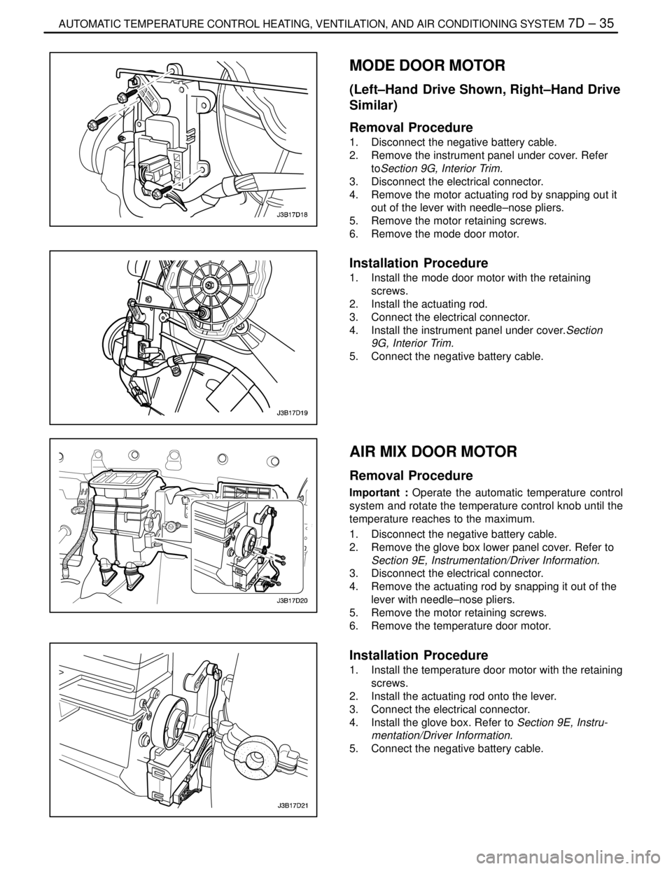
MODE DOOR MOTOR
(Left–Hand Drive Shown, Right–Hand Drive
Similar)
Removal Procedure
1. Disconnect the negative battery cable.
2. Remove the instrument panel under cover. Refer
toSection 9G, Interior Trim.
3. Disconnect the electrical connector.
4. Remove the motor actuating rod by snapping out it
out of the lever with needle–nose pliers.
5. Remove the motor retaining screws.
6. Remove the mode door motor.
Installation Procedure
1. Install the mode door motor with the retaining
screws.
2. Install the actuating rod.
3. Connect the electrical connector.
4. Install the instrument panel under cover.Section
9G, Interior Trim.
5. Connect the negative battery cable.
AIR MIX DOOR MOTOR
Removal Procedure
Important : Operate the automatic temperature control
system and rotate the temperature control knob until the
temperature reaches to the maximum.
1. Disconnect the negative battery cable.
2. Remove the glove box lower panel cover. Refer to
Section 9E, Instrumentation/Driver Information.
3. Disconnect the electrical connector.
4. Remove the actuating rod by snapping it out of the
lever with needle–nose pliers.
5. Remove the motor retaining screws.
6. Remove the temperature door motor.
Installation Procedure
1. Install the temperature door motor with the retaining
screws.
2. Install the actuating rod onto the lever.
3. Connect the electrical connector.
4. Install the glove box. Refer to Section 9E, Instru-
mentation/Driver Information.
5. Connect the negative battery cable.
Page 2199 of 2643

SUPPLEMENTAL INFLATABLE RESTRAINTS (SIR) 8B – 95
DAEWOO V–121 BL4
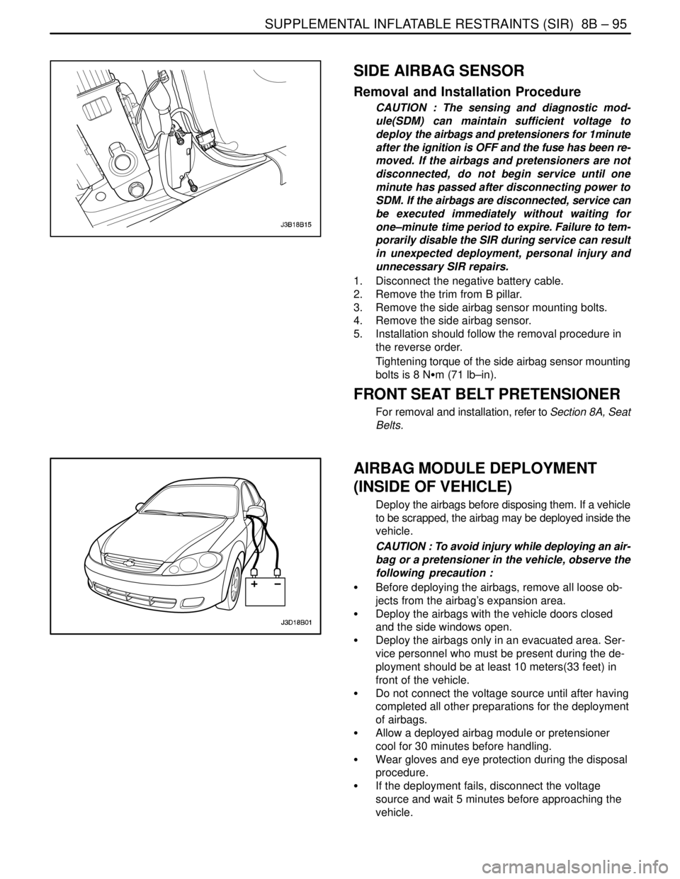
SIDE AIRBAG SENSOR
Removal and Installation Procedure
CAUTION : The sensing and diagnostic mod-
ule(SDM) can maintain sufficient voltage to
deploy the airbags and pretensioners for 1minute
after the ignition is OFF and the fuse has been re-
moved. If the airbags and pretensioners are not
disconnected, do not begin service until one
minute has passed after disconnecting power to
SDM. If the airbags are disconnected, service can
be executed immediately without waiting for
one–minute time period to expire. Failure to tem-
porarily disable the SIR during service can result
in unexpected deployment, personal injury and
unnecessary SIR repairs.
1. Disconnect the negative battery cable.
2. Remove the trim from B pillar.
3. Remove the side airbag sensor mounting bolts.
4. Remove the side airbag sensor.
5. Installation should follow the removal procedure in
the reverse order.
Tightening torque of the side airbag sensor mounting
bolts is 8 NSm (71 lb–in).
FRONT SEAT BELT PRETENSIONER
For removal and installation, refer to Section 8A, Seat
Belts.
AIRBAG MODULE DEPLOYMENT
(INSIDE OF VEHICLE)
Deploy the airbags before disposing them. If a vehicle
to be scrapped, the airbag may be deployed inside the
vehicle.
CAUTION : To avoid injury while deploying an air-
bag or a pretensioner in the vehicle, observe the
following precaution :
S Before deploying the airbags, remove all loose ob-
jects from the airbag’s expansion area.
S Deploy the airbags with the vehicle doors closed
and the side windows open.
S Deploy the airbags only in an evacuated area. Ser-
vice personnel who must be present during the de-
ployment should be at least 10 meters(33 feet) in
front of the vehicle.
S Do not connect the voltage source until after having
completed all other preparations for the deployment
of airbags.
S Allow a deployed airbag module or pretensioner
cool for 30 minutes before handling.
S Wear gloves and eye protection during the disposal
procedure.
S If the deployment fails, disconnect the voltage
source and wait 5 minutes before approaching the
vehicle.
Page 2272 of 2643

9B – 46ILITHING SYSTEMS
DAEWOO V–121 BL4
GENERAL DESCRIPTION
AND SYSTEM OPERATION
HEADLAMPS–ON REMINDER CHIME
When the headlamp switch is in the headlamps–on or
parking lamps–on position, voltage is applied to the chime
module. When the ignition is in ON, ACC or START, volt-
age is applied through the fuse block to the module. These
two voltages are sensed, and the chime module is not
sounded.
When the ignition is not in ON, ACC or START, the module
loses voltage. The chime module senses change. If the
voltage is still available, it is applied to sound the chime.
The chime can be turned off by turning the headlamp
switch off. The module no longer senses voltage from the
headlamp switch, so the chime module does not sound.
HEADLAMPS
The headlamps are controlled by the multifunction lever
located on the left side of the steering column. They will
come on with the ignition switch in any position. Turning
the headlamp switch to the first position turns on the park-
ing lamps, the license plate lamps and the instrument pan-
el illumination. Turning the switch to the second position
turns on all of the previous lamps and the headlamps.
Turning the switch to the OFF position turns off all the
lamps.
Headlamp high beams and low beams are also controlled
by this lever. When the headlamps are on, pushing the le-
ver away from the driver until the switch clicks changes the
lamp from low beam to high beam. An indicator lamp on
the instrument cluster assembly will come on when the
high beam headlamps are on. To return the headlamps to
low beam, pull the lever toward the driver.
The headlamps must be aimed for proper illumination of
the road. Headlamp aim should be checked whenever a
new headlamp assembly is installed, or whenever service
repairs to the front end area may have disturbed the head-
lamp assembly or its mountings.
DAYTIME RUNNING LAMPS
The Daytime Running Lamps (DRL) will come on when:
S The ignition is ON.
S The light is OFF.
S The parking brake is released.
When the exterior lights are on, the DRL will turn off. To
turn the DRL off when idling, apply the parking brake.
PARKING AND TURN SIGNAL LAMPS
The parking lamps can be turned on by turning the lighting
switch to the first position. The parking lamps can be
turned off by turning the switch to the OFF position.When the turn signals are activated, the front and rear turn
signal lamps flash to signal a turn. The turn signals work
only when the ignition is ON.
The turn signals are controlled by the light switch on the
left side of the steering column. Moving the lever all the
way up or down (past the detent) will turn on the front and
rear turn signals. When the turn is completed, the lever will
return to horizontal and the turn signals will stop flashing.
For changing lanes, or for shallow turns in which the steer-
ing wheel does not turn far enough to cancel the signal,
move the signal lever only to the first detent and hold it
there. When the lever is released, it will return to horizontal
and the turn signals will cancel.
FOG LAMPS
The fog lamp switch is on the instrument panel to the right
of the steering column. To use the fog lamps, first turn on
the headlamps or the parking lamps. Then push the fog
lamp switch. The indicator light in the switch will illuminate
to indicate that the fog lamps are on. Push the switch again
to turn off the fog lamps. The indicator light will then go off.
The fog lamps should not be used as a substitute for the
headlamps.
The fog lamps must be aimed for proper illumination of the
road. Fog lamp aim should be checked when a new bulb
is installed or if service or repairs in the front end area may
have disturbed the fog lamp mountings.
REAR COMBINATION LAMPS
The taillamps, stoplamps, turn signal lamps and backup
lamp are one assembly.
Turning on either the headlamps or the parking lamps will
also turn on the taillamps. When the brake pedal is
pushed, the taillamps will glow brighter to serve as sto-
plamps.
The center high–mounted stoplamp is located in the rear
window and will come on when the brake pedal is pressed.
LICENSE PLATE LAMP
The license plate lamps will come on when the headlamps
or the parking lamps are on. The license plate lamps are
mounted above the license plate.
INTERIOR COURTESY LAMP
The courtesy lamp is located on the headliner just behind
the front seats. The lamp switch has three positions. If the
switch is left in the center position, the lamp will go on
whenever a door is opened and go off when it is closed.
In the ON position, the lamp will stay on until it is turned off.
In the OFF position, the lamp will not come on, even when
a door is opened.
LUGGAGE COMPARTMENT LAMP
The luggage compartment lamp is located under the deck
lid sill plate on the notchback. The lamp is located on the
left–side wheelhouse trim panel on the hatchback. It will
come on whenever the luggage compartment is opened.
Page 2297 of 2643

9D – 20IWIPERS/WASHER SYSTEMS
DAEWOO V–121 BL4
Installation Procedure
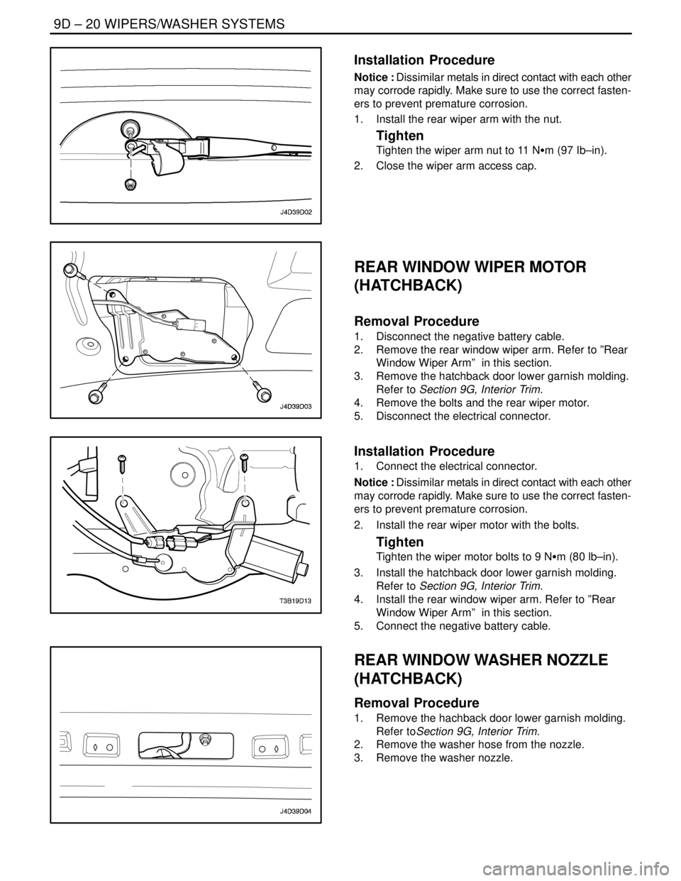
Notice : Dissimilar metals in direct contact with each other
may corrode rapidly. Make sure to use the correct fasten-
ers to prevent premature corrosion.
1. Install the rear wiper arm with the nut.
Tighten
Tighten the wiper arm nut to 11 NSm (97 Ib–in).
2. Close the wiper arm access cap.
REAR WINDOW WIPER MOTOR
(HATCHBACK)
Removal Procedure
1. Disconnect the negative battery cable.
2. Remove the rear window wiper arm. Refer to ”Rear
Window Wiper Arm” in this section.
3. Remove the hatchback door lower garnish molding.
Refer to Section 9G, Interior Trim.
4. Remove the bolts and the rear wiper motor.
5. Disconnect the electrical connector.
Installation Procedure
1. Connect the electrical connector.
Notice : Dissimilar metals in direct contact with each other
may corrode rapidly. Make sure to use the correct fasten-
ers to prevent premature corrosion.
2. Install the rear wiper motor with the bolts.
Tighten
Tighten the wiper motor bolts to 9 NSm (80 lb–in).
3. Install the hatchback door lower garnish molding.
Refer to Section 9G, Interior Trim.
4. Install the rear window wiper arm. Refer to ”Rear
Window Wiper Arm” in this section.
5. Connect the negative battery cable.
REAR WINDOW WASHER NOZZLE
(HATCHBACK)
Removal Procedure
1. Remove the hachback door lower garnish molding.
Refer toSection 9G, Interior Trim.
2. Remove the washer hose from the nozzle.
3. Remove the washer nozzle.
Page 2298 of 2643

WIPERS/WASHER SYSTEMS 9D – 21
DAEWOO V–121 BL4
Installation Procedure
1. Install the washer nozzle.
2. Install the washer hose to the nozzle.
3. Install the hachback door lower garnish molding.
Refer toSection 9G, Interior Trim.
Page 2301 of 2643

9E – 2IINSTRUMENTATION/DRIVER INFORMATION
DAEWOO V–121 BL4
SPECIFICATIONS
FASTENER TIGHTENING SPECIFICATIONS
ApplicationNSmLb–FtLb–In
Air Deflector Screws2–18
Chime Module Screws4–35
Clock Screws2–18
Cupholder Screws2.5–22
Deposit Box Screws2.5–22
Driver Knee Bolster Bolts10–89
Floor Console Brace Bolts4–35
Floor Console Brace Nuts4–35
HVAC Controls Screws4–35
Instrument Cluster Screws4–35
Instrument Cluster Trim Panel Screws4–35
Instrument Panel End Bolts2015–
Instrument Panel End Screws4–35
Instrument Panel Nuts Above the Steering Column2015–
Instrument Panel Bolts Behind the HVAC Controls4–35
Steering Column Bracket Nut2216–
Steering Column Lower Trim Cover Screws2.5–22
Steering Column U–Clamp Nuts2216–
Steering Column Upper Trim Cover Screws3–27
INSTRUMENT CLUSTER INDICATOR LAMPS
SPECIFICATIONS
Indicator LampColorBulb
ABS WarningAmber14 v 1.4 W
Airbag WarningRed14 v 1.4 W
Battery Charge IndicatorRed14 v 1.4 W
Check EngineAmber14 v 1.4 W
Door Open WarningRed14 v 1.4 W
Engine OverheatRed14 v 1.4 W
Fasten Seat Belt WarningRed14 v 1.4 W
High Beam IndicatorBlue14 v 1.4 W
Low Fuel Level WarningAmber14 v 4 W
Oil Pressure WarningRed14 v 1.4 W
Parking Brake Indicator and Brake Fluid WarningRed14 v 1.4 W
Service Engine Soon WarningAmber14 v 1.4 W
Transaxle Power Mode IndicatorAmber14 v 1.4 W
Turn Signal IndicatorsGreen14 v 1.4 W
Page 2317 of 2643

9E – 18IINSTRUMENTATION/DRIVER INFORMATION
DAEWOO V–121 BL4
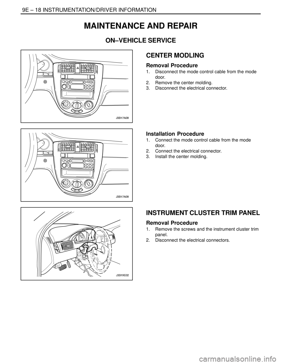
MAINTENANCE AND REPAIR
ON–VEHICLE SERVICE
CENTER MODLING
Removal Procedure
1. Disconnect the mode control cable from the mode
door.
2. Remove the center molding.
3. Disconnect the electrical connector.
Installation Procedure
1. Connect the mode control cable from the mode
door.
2. Connect the electrical connector.
3. Install the center molding.
INSTRUMENT CLUSTER TRIM PANEL
Removal Procedure
1. Remove the screws and the instrument cluster trim
panel.
2. Disconnect the electrical connectors.