2004 CHRYSLER VOYAGER psi
[x] Cancel search: psiPage 2096 of 2585
pressures may increase from 2 to 6 pounds per
square inch (psi) (14 to 41 kPa) during operation. Do
not reduce this normal pressure buildup.
Improper inflation can cause:
²Uneven wear patterns
²Reduced tread life
²Reduced fuel economy
²Unsatisfactory ride
²The vehicle to drift.
WARNING: OVER OR UNDER INFLATED TIRES CAN
AFFECT VEHICLE HANDLING. THE TIRE CAN FAIL
SUDDENLY, RESULTING IN LOSS OF VEHICLE
CONTROL.
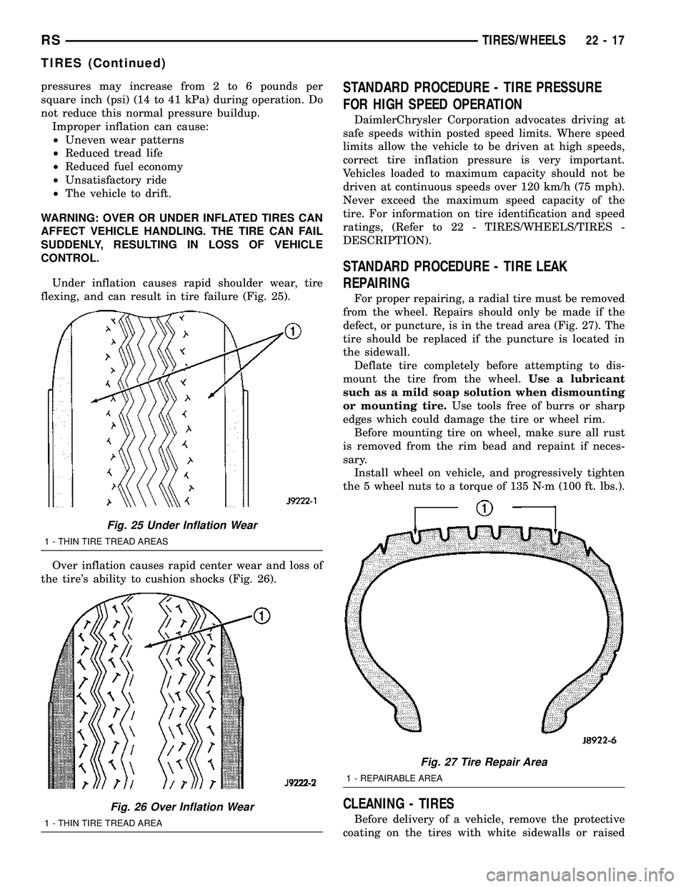
Under inflation causes rapid shoulder wear, tire
flexing, and can result in tire failure (Fig. 25).
Over inflation causes rapid center wear and loss of
the tire's ability to cushion shocks (Fig. 26).STANDARD PROCEDURE - TIRE PRESSURE
FOR HIGH SPEED OPERATION
DaimlerChrysler Corporation advocates driving at
safe speeds within posted speed limits. Where speed
limits allow the vehicle to be driven at high speeds,
correct tire inflation pressure is very important.
Vehicles loaded to maximum capacity should not be
driven at continuous speeds over 120 km/h (75 mph).
Never exceed the maximum speed capacity of the
tire. For information on tire identification and speed
ratings, (Refer to 22 - TIRES/WHEELS/TIRES -
DESCRIPTION).
STANDARD PROCEDURE - TIRE LEAK
REPAIRING
For proper repairing, a radial tire must be removed
from the wheel. Repairs should only be made if the
defect, or puncture, is in the tread area (Fig. 27). The
tire should be replaced if the puncture is located in
the sidewall.
Deflate tire completely before attempting to dis-
mount the tire from the wheel.Use a lubricant
such as a mild soap solution when dismounting
or mounting tire.Use tools free of burrs or sharp
edges which could damage the tire or wheel rim.
Before mounting tire on wheel, make sure all rust
is removed from the rim bead and repaint if neces-
sary.
Install wheel on vehicle, and progressively tighten
the 5 wheel nuts to a torque of 135 N´m (100 ft. lbs.).
CLEANING - TIRES
Before delivery of a vehicle, remove the protective
coating on the tires with white sidewalls or raised
Fig. 25 Under Inflation Wear
1 - THIN TIRE TREAD AREAS
Fig. 26 Over Inflation Wear
1 - THIN TIRE TREAD AREA
Fig. 27 Tire Repair Area
1 - REPAIRABLE AREA
RSTIRES/WHEELS22-17
TIRES (Continued)
Page 2103 of 2585
CAUTION: Do not try to install a tire pressure sen-
sor in a steel wheel or aftermarket wheel. Use only
in original style factory wheels.
OPERATION
The tire pressure sensors are battery operated.
Each sensor transmits tire pressure data approxi-
mately once every minute at speeds above 13 mph
(20 km/h). Each sensor's (transmitter) broadcast is
uniquely coded so that the SKREEM can monitor the
states of each individual sensor on the vehicle.
Unlike prior model year TPM systems, a magnet is
not required to retrain the system. The SKREEM
automatically learns while driving after a sensor has
been replaced. (Refer to 22 - TIRES/WHEELS/TIRE
PRESSURE MONITORING/SENSOR - STANDARD
PROCEDURE) For additional information, refer to Appropriate
Diagnostic Information.
CAUTION
CAUTION: The use of tire sealants is strictly prohib-
ited for vehicles equipped with the Tire Pressure
Monitoring system. Tire sealants can clog tire pres-
sure sensors.
CAUTION: Tire pressure sensor valve stem caps
and cores are specially designed for the sensors.
Due to risk of corrosion, do not use a standard
valve stem cap or core in a tire pressure sensor in
place of the original equipment style sensor cap
and core.
CAUTION: Do not attempt to install a tire pressure
sensor in a steel wheel or aftermarket wheel. Use
tire pressure sensors in original style factory
wheels only.
NOTE: TPM thresholds have been established for
the original tire size equipped on the vehicle. Use
original size tires only to maintain system accuracy.
DIAGNOSIS AND TESTING - TIRE PRESSURE
SENSOR
NOTE: Tire pressure may increase from 2 to 6 psi
(14 to 41 kPa) during normal driving conditions. Do
NOT reduce this normal pressure build up.
If a fault in the system is detected, always check
air pressure in the tires first with a known accurate
air gauge and correct the inflation pressure. If any
tire is low, inspect allthe tires. If the gauge-read pressure in the tires does not
indicate a tire pressure issue, refer to the appropri-
ate diagnostic information.
STANDARD PROCEDURE - TIRE PRESSURE
SENSOR RETRAIN
CAUTION: If a sensor is replaced, the vehicle must
be parked for a minimum of 15 minutes for the sys-
tem to be ready to learn the new sensor ID code.
(1) Park the car for a minimum of 15 minutes.
(2) Drive the vehicle for a minimum of five min-
utes while maintaining a continuous speed above 13
mph (20 km/h). During this time the system will
learn the new sensor ID code and will clear any
DTC's automatically.
NOTE: If a sensor cannot be trained, refer to appro-
priate diagnostic information.
REMOVAL
(1) Remove tire and wheel assembly from vehicle.
(Refer to 22 - TIRES/WHEELS - REMOVAL)
CAUTION: The cap used on this valve stem con-
tains an O-ring seal to prevent contamination and
moisture from entering the valve stem. Retain this
valve stem cap for reuse. Do not substitute a regu-
lar valve stem cap in its place.
CAUTION: The valve stem used on this vehicle is
made of aluminum and the core is nickel plated
brass. The original valve stem core must be rein-
stalled and not substituted with a valve stem core
made of a different material. This is required to pre-
vent corrosion in the valve stem caused by the dif-
ferent metals.
(2) Dismount tire from wheel following tire
changer manufacturers instructions while paying
special attention to the following to avoid damaging
the pressure sensor: (a) When breaking the tire bead loose from the
wheel rim, avoid using the Bead Breaker in the
area of the sensor. That includes both front and
rear beads of the tire. (b) When preparing to dismount the tire from
the wheel, carefully insert the mounting/dimount-
ing tool at the valve stem 10É (Fig. 1), then pro-
ceed to dismount the tire from the wheel. Use this
process on both the upper and lower tire beads.
(3) Using a thin wall socket, remove special nut
retaining sensor to wheel (Fig. 2). (4) Remove sensor from wheel (Fig. 2).
22s - 2 TIRE PRESSURE MONITORINGRS
SENSOR - TPM (Continued)
Page 2110 of 2585
pressures may increase from 2 to 6 pounds per
square inch (psi) (14 to 41 kPa) during operation. Do
not reduce this normal pressure buildup.Improper inflation can cause:
² Uneven wear patterns
² Reduced tread life
² Reduced fuel economy
² Unsatisfactory ride
² The vehicle to drift.
WARNING: OVER OR UNDER INFLATED TIRES CAN
AFFECT VEHICLE HANDLING. THE TIRE CAN FAIL
SUDDENLY, RESULTING IN LOSS OF VEHICLE
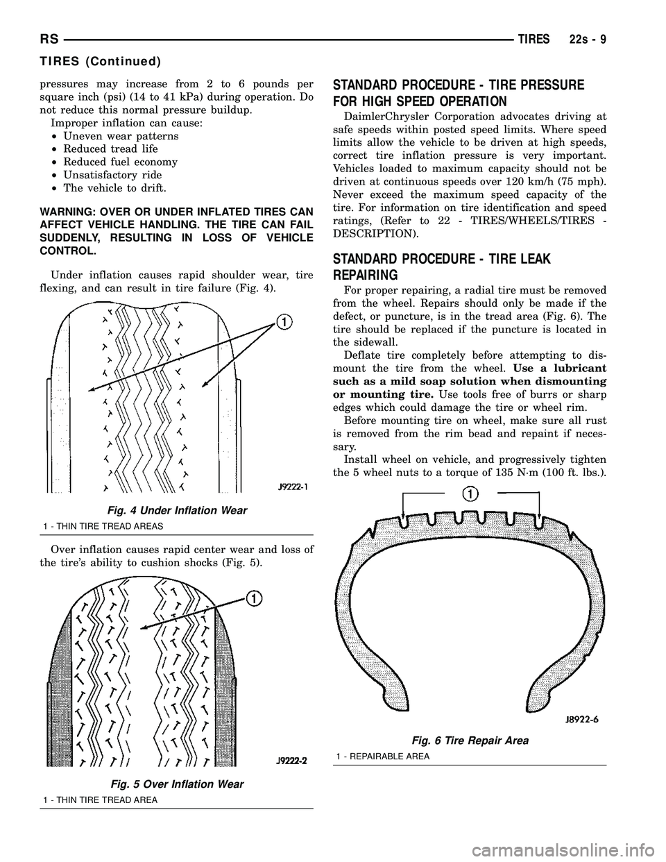
CONTROL. Under inflation causes rapid shoulder wear, tire
flexing, and can result in tire failure (Fig. 4).
Over inflation causes rapid center wear and loss of
the tire's ability to cushion shocks (Fig. 5).STANDARD PROCEDURE - TIRE PRESSURE
FOR HIGH SPEED OPERATION
DaimlerChrysler Corporation advocates driving at
safe speeds within posted speed limits. Where speed
limits allow the vehicle to be driven at high speeds,
correct tire inflation pressure is very important.
Vehicles loaded to maximum capacity should not be
driven at continuous speeds over 120 km/h (75 mph).
Never exceed the maximum speed capacity of the
tire. For information on tire identification and speed
ratings, (Refer to 22 - TIRES/WHEELS/TIRES -
DESCRIPTION).
STANDARD PROCEDURE - TIRE LEAK
REPAIRING
For proper repairing, a radial tire must be removed
from the wheel. Repairs should only be made if the
defect, or puncture, is in the tread area (Fig. 6). The
tire should be replaced if the puncture is located in
the sidewall. Deflate tire completely before attempting to dis-
mount the tire from the wheel. Use a lubricant
such as a mild soap solution when dismounting
or mounting tire. Use tools free of burrs or sharp
edges which could damage the tire or wheel rim. Before mounting tire on wheel, make sure all rust
is removed from the rim bead and repaint if neces-
sary. Install wheel on vehicle, and progressively tighten
the 5 wheel nuts to a torque of 135 N´m (100 ft. lbs.).
Fig. 4 Under Inflation Wear
1 - THIN TIRE TREAD AREAS
Fig. 5 Over Inflation Wear
1 - THIN TIRE TREAD AREA
Fig. 6 Tire Repair Area
1 - REPAIRABLE AREA
RS TIRES22s-9
TIRES (Continued)
Page 2403 of 2585
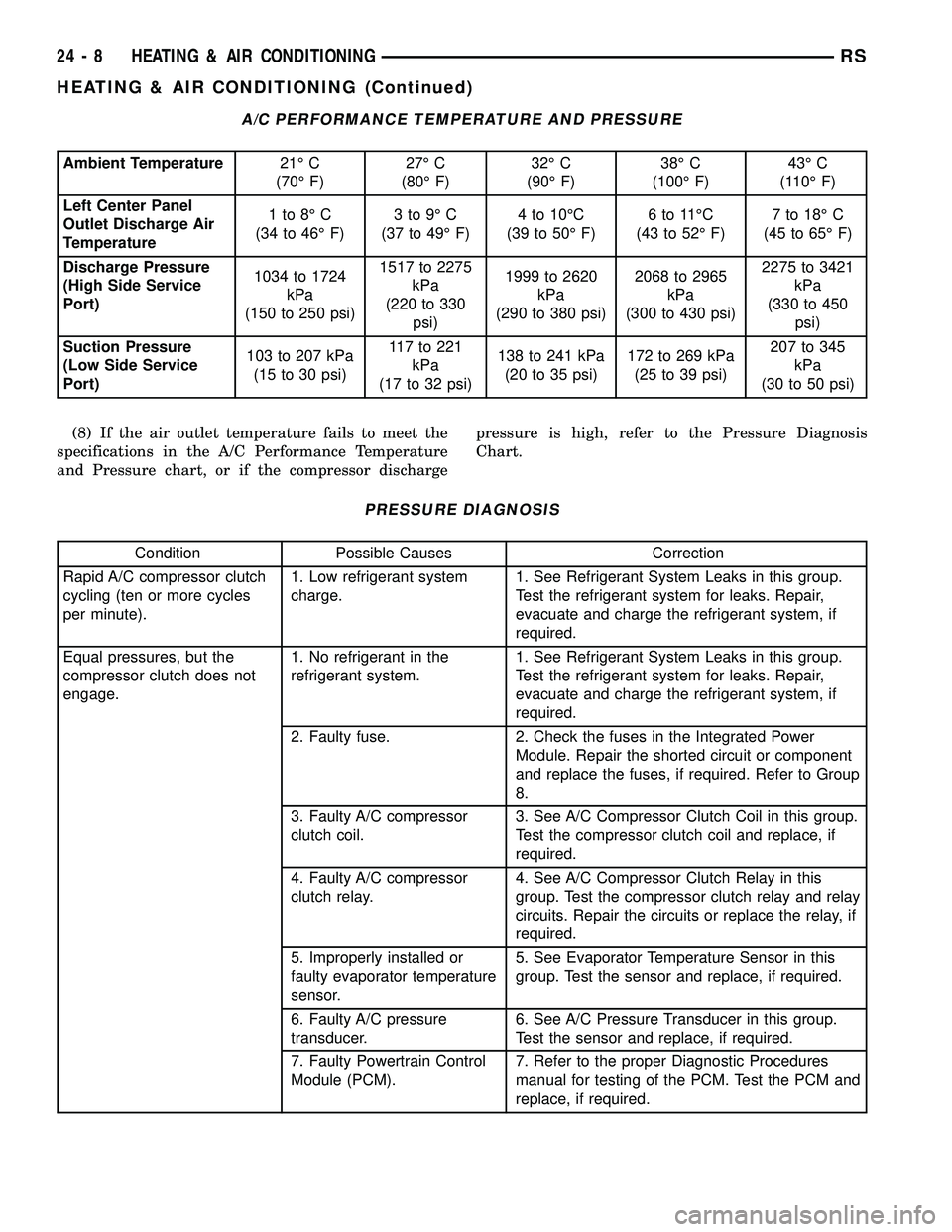
A/C PERFORMANCE TEMPERATURE AND PRESSURE
Ambient Temperature21É C
(70É F)27É C
(80É F)32É C
(90É F)38É C
(100É F)43É C
(110É F)
Left Center Panel
Outlet Discharge Air
Temperature1to8ÉC
(34 to 46É F)3to9ÉC
(37 to 49É F)4 to 10ÉC
(39 to 50É F)6to11ÉC
(43 to 52É F)7 to 18É C
(45 to 65É F)
Discharge Pressure
(High Side Service
Port)1034 to 1724
kPa
(150 to 250 psi)1517 to 2275
kPa
(220 to 330
psi)1999 to 2620
kPa
(290 to 380 psi)2068 to 2965
kPa
(300 to 430 psi)2275 to 3421
kPa
(330 to 450
psi)
Suction Pressure
(Low Side Service
Port)103 to 207 kPa
(15 to 30 psi)117to221
kPa
(17 to 32 psi)138 to 241 kPa
(20 to 35 psi)172 to 269 kPa
(25 to 39 psi)207 to 345
kPa
(30 to 50 psi)
(8) If the air outlet temperature fails to meet the
specifications in the A/C Performance Temperature
and Pressure chart, or if the compressor dischargepressure is high, refer to the Pressure Diagnosis
Chart.
PRESSURE DIAGNOSIS
Condition Possible Causes Correction
Rapid A/C compressor clutch
cycling (ten or more cycles
per minute).1. Low refrigerant system
charge.1. See Refrigerant System Leaks in this group.
Test the refrigerant system for leaks. Repair,
evacuate and charge the refrigerant system, if
required.
Equal pressures, but the
compressor clutch does not
engage.1. No refrigerant in the
refrigerant system.1. See Refrigerant System Leaks in this group.
Test the refrigerant system for leaks. Repair,
evacuate and charge the refrigerant system, if
required.
2. Faulty fuse. 2. Check the fuses in the Integrated Power
Module. Repair the shorted circuit or component
and replace the fuses, if required. Refer to Group
8.
3. Faulty A/C compressor
clutch coil.3. See A/C Compressor Clutch Coil in this group.
Test the compressor clutch coil and replace, if
required.
4. Faulty A/C compressor
clutch relay.4. See A/C Compressor Clutch Relay in this
group. Test the compressor clutch relay and relay
circuits. Repair the circuits or replace the relay, if
required.
5. Improperly installed or
faulty evaporator temperature
sensor.5. See Evaporator Temperature Sensor in this
group. Test the sensor and replace, if required.
6. Faulty A/C pressure
transducer.6. See A/C Pressure Transducer in this group.
Test the sensor and replace, if required.
7. Faulty Powertrain Control
Module (PCM).7. Refer to the proper Diagnostic Procedures
manual for testing of the PCM. Test the PCM and
replace, if required.
24 - 8 HEATING & AIR CONDITIONINGRS
HEATING & AIR CONDITIONING (Continued)
Page 2406 of 2585
MECHANICAL PROBLEMS
Possible causes of insufficient heat due to mechan-
ical problems are as follows:
²Obstructed cowl air intake.
²Obstructed heater system outlets.
²Blend door not functioning properly.
TEMPERATURE CONTROL
If the heater outlet air temperature cannot be
adjusted with the temperature control knob on the
A/C-heater control panel, the following could require
service:
²Blend door binding.²Faulty blend door actuator.
²Faulty A/C-heater control.
²Faulty related wiring harness or connectors.
²Improper engine coolant temperature.
SPECIFICATIONS
A/C SYSTEM
The R-134a refrigerant system charge capacity for
this vehicle can be found on the underhood Specifica-
tion Label.
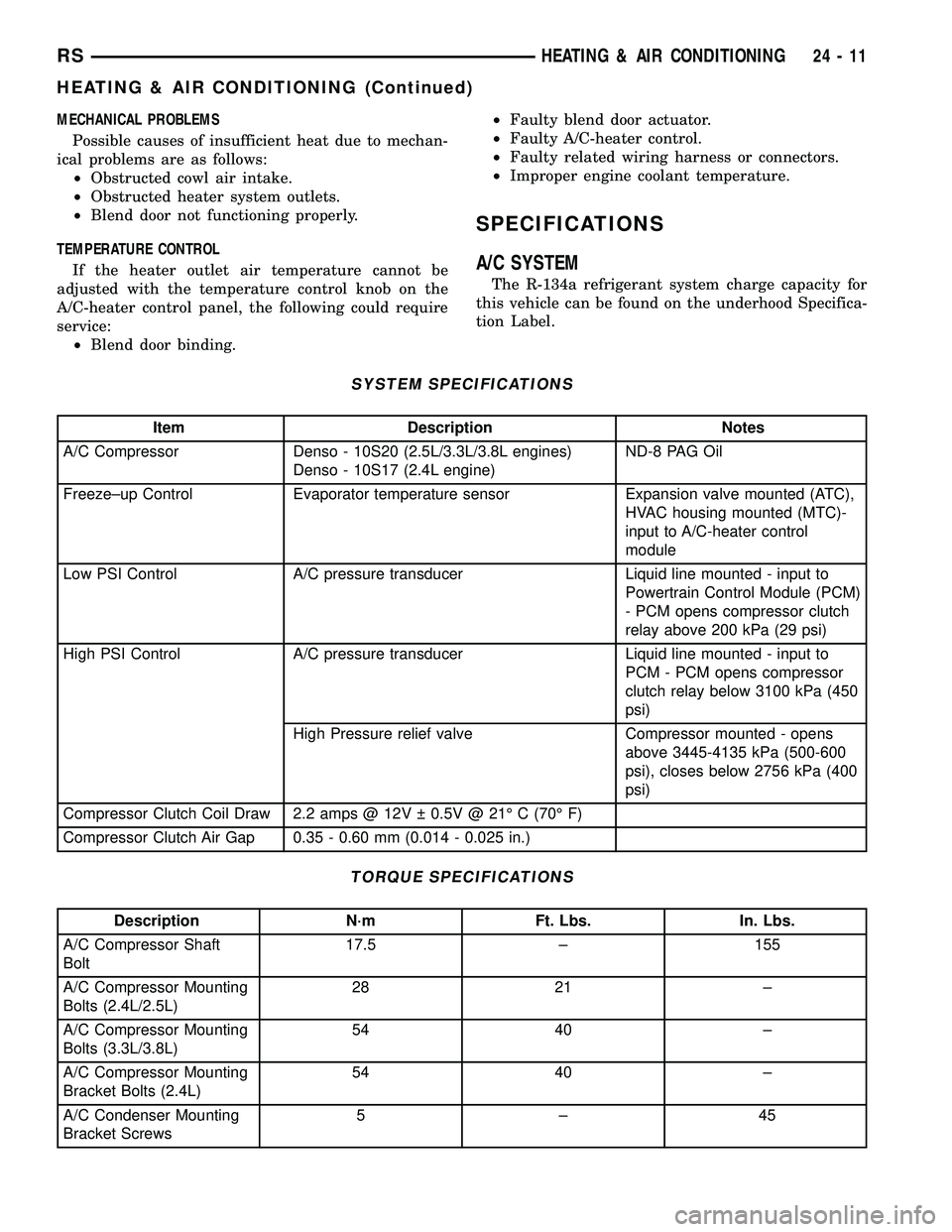
SYSTEM SPECIFICATIONS
Item Description Notes
A/C Compressor Denso - 10S20 (2.5L/3.3L/3.8L engines)
Denso - 10S17 (2.4L engine)ND-8 PAG Oil
Freeze±up Control Evaporator temperature sensor Expansion valve mounted (ATC),
HVAC housing mounted (MTC)-
input to A/C-heater control
module
Low PSI Control A/C pressure transducer Liquid line mounted - input to
Powertrain Control Module (PCM)
- PCM opens compressor clutch
relay above 200 kPa (29 psi)
High PSI Control A/C pressure transducer Liquid line mounted - input to
PCM - PCM opens compressor
clutch relay below 3100 kPa (450
psi)
High Pressure relief valve Compressor mounted - opens
above 3445-4135 kPa (500-600
psi), closes below 2756 kPa (400
psi)
Compressor Clutch Coil Draw 2.2 amps @ 12V 0.5V @ 21É C (70É F)
Compressor Clutch Air Gap 0.35 - 0.60 mm (0.014 - 0.025 in.)
TORQUE SPECIFICATIONS
Description N´m Ft. Lbs. In. Lbs.
A/C Compressor Shaft
Bolt17.5 ± 155
A/C Compressor Mounting
Bolts (2.4L/2.5L)28 21 ±
A/C Compressor Mounting
Bolts (3.3L/3.8L)54 40 ±
A/C Compressor Mounting
Bracket Bolts (2.4L)54 40 ±
A/C Condenser Mounting
Bracket Screws5±45
RSHEATING & AIR CONDITIONING24-11
HEATING & AIR CONDITIONING (Continued)
Page 2410 of 2585
A/C COMPRESSOR CLUTCH/
COIL
DESCRIPTION
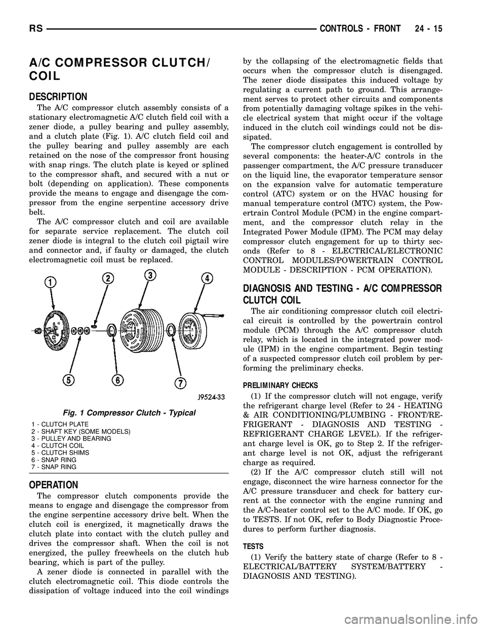
The A/C compressor clutch assembly consists of a
stationary electromagnetic A/C clutch field coil with a
zener diode, a pulley bearing and pulley assembly,
and a clutch plate (Fig. 1). A/C clutch field coil and
the pulley bearing and pulley assembly are each
retained on the nose of the compressor front housing
with snap rings. The clutch plate is keyed or splined
to the compressor shaft, and secured with a nut or
bolt (depending on application). These components
provide the means to engage and disengage the com-
pressor from the engine serpentine accessory drive
belt.
The A/C compressor clutch and coil are available
for separate service replacement. The clutch coil
zener diode is integral to the clutch coil pigtail wire
and connector and, if faulty or damaged, the clutch
electromagnetic coil must be replaced.
OPERATION
The compressor clutch components provide the
means to engage and disengage the compressor from
the engine serpentine accessory drive belt. When the
clutch coil is energized, it magnetically draws the
clutch plate into contact with the clutch pulley and
drives the compressor shaft. When the coil is not
energized, the pulley freewheels on the clutch hub
bearing, which is part of the pulley.
A zener diode is connected in parallel with the
clutch electromagnetic coil. This diode controls the
dissipation of voltage induced into the coil windingsby the collapsing of the electromagnetic fields that
occurs when the compressor clutch is disengaged.
The zener diode dissipates this induced voltage by
regulating a current path to ground. This arrange-
ment serves to protect other circuits and components
from potentially damaging voltage spikes in the vehi-
cle electrical system that might occur if the voltage
induced in the clutch coil windings could not be dis-
sipated.
The compressor clutch engagement is controlled by
several components: the heater-A/C controls in the
passenger compartment, the A/C pressure transducer
on the liquid line, the evaporator temperature sensor
on the expansion valve for automatic temperature
control (ATC) system or on the HVAC housing for
manual temperature control (MTC) system, the Pow-
ertrain Control Module (PCM) in the engine compart-
ment, and the compressor clutch relay in the
Integrated Power Module (IPM). The PCM may delay
compressor clutch engagement for up to thirty sec-
onds (Refer to 8 - ELECTRICAL/ELECTRONIC
CONTROL MODULES/POWERTRAIN CONTROL
MODULE - DESCRIPTION - PCM OPERATION).
DIAGNOSIS AND TESTING - A/C COMPRESSOR
CLUTCH COIL
The air conditioning compressor clutch coil electri-
cal circuit is controlled by the powertrain control
module (PCM) through the A/C compressor clutch
relay, which is located in the integrated power mod-
ule (IPM) in the engine compartment. Begin testing
of a suspected compressor clutch coil problem by per-
forming the preliminary checks.
PRELIMINARY CHECKS
(1) If the compressor clutch will not engage, verify
the refrigerant charge level (Refer to 24 - HEATING
& AIR CONDITIONING/PLUMBING - FRONT/RE-
FRIGERANT - DIAGNOSIS AND TESTING -
REFRIGERANT CHARGE LEVEL). If the refriger-
ant charge level is OK, go to Step 2. If the refriger-
ant charge level is not OK, adjust the refrigerant
charge as required.
(2) If the A/C compressor clutch still will not
engage, disconnect the wire harness connector for the
A/C pressure transducer and check for battery cur-
rent at the connector with the engine running and
the A/C-heater control set to the A/C mode. If OK, go
to TESTS. If not OK, refer to Body Diagnostic Proce-
dures to perform further diagnosis.
TESTS
(1) Verify the battery state of charge (Refer to 8 -
ELECTRICAL/BATTERY SYSTEM/BATTERY -
DIAGNOSIS AND TESTING).
Fig. 1 Compressor Clutch - Typical
1 - CLUTCH PLATE
2 - SHAFT KEY (SOME MODELS)
3 - PULLEY AND BEARING
4 - CLUTCH COIL
5 - CLUTCH SHIMS
6 - SNAP RING
7 - SNAP RING
RSCONTROLS - FRONT24-15
Page 2461 of 2585
CAUTION
A/C SYSTEM
CAUTION: Liquid refrigerant is corrosive to metal
surfaces. Follow the operating instructions supplied
with the service equipment being used.
Never add R-12 to a refrigerant system designed to
use R-134a and do not use R-12 equipment or parts
on the R-134a system. Damage to the system will
result.
R-12 refrigerant oil must not be mixed with R-134a
refrigerant oil. They are not compatible and damage
to the system will result.
Do not overcharge the refrigerant system. Over-
charging will cause excessive compressor head
pressure and can cause noise and system failure.
Recover the refrigerant before opening any fitting
or connection. Open the fittings with caution, even
after the system has been discharged. Never open
or loosen a connection before recovering the refrig-
erant.
If equipped, do not remove the secondary retention
clip from any spring-lock coupler connection while
the refrigerant system is under pressure. Recover
the refrigerant before removing the secondary
retention clip. Open the fittings with caution, even
after the system has been discharged. Never open
or loosen a connection before recovering the refrig-
erant.
Do not open the refrigerant system or uncap a
replacement component until you are ready to ser-
vice the system. This will prevent contamination in
the system. Before disconnecting a component,
clean the outside of the fittings thoroughly to pre-
vent contamination from entering the refrigerant
system. Immediately after disconnecting a compo-
nent from the refrigerant system, seal the open fit-
tings with a cap or plug.
Refrigerant oil will absorb moisture from the atmo-
sphere if left uncapped. Do not open a container of
refrigerant oil until you are ready to use it. Replace
the cap on the oil container immediately after using.
Store refrigerant oil only in a clean, airtight, and
moisture-free container.
Keep service tools and the work area clean. Con-
tamination of the refrigerant system must be
avoided.
CAUTION: The use of A/C system sealers may
result in damage to A/C refrigerant recovery/evacu-
ation/recharging equipment and/or A/C systems.
Many federal, state/provincial and local regulations
prohibit the recharge of A/C systems with known
leaks. DaimlerChrysler recommends the detection
of A/C system leaks through the use of approvedleak detectors and fluorescent leak detection dyes.
Vehicles found with A/C system sealers should be
treated as contaminated and replacement of the
entire A/C refrigerant system is recommended. A/C
systems found to be contaminated with A/C system
sealers, A/C stop-leak products or seal conditioners
voids the warranty for the A/C system.
DIAGNOSIS AND TESTING
DIAGNOSIS AND TESTING - REFRIGERANT
SYSTEM LEAKS
WARNING: R-134a SERVICE EQUIPMENT OR VEHI-
CLE A/C SYSTEM SHOULD NOT BE PRESSURE
TESTED OR LEAK TESTED WITH COMPRESSED
AIR. MIXTURE OF AIR and R-134a CAN BE COM-
BUSTIBLE AT ELEVATED PRESSURES. THESE MIX-
TURES ARE POTENTIALLY DANGEROUS AND MAY
RESULT IN FIRE OR EXPLOSION CAUSING INJURY
OR PROPERTY DAMAGE.
AVOID BREATHING A/C REFRIGERANT AND LUBRI-
CANT VAPOR OR MIST. EXPOSURE MAY IRRITATE
EYES, NOSE AND THROAT. USE ONLY APPROVED
SERVICE EQUIPMENT MEETING SAE REQUIRE-
MENTS TO DISCHARGE R-134a SYSTEM. IF ACCI-
DENTAL SYSTEM DISCHARGE OCCURS,
VENTILATE WORK AREA BEFORE RESUMING SER-
VICE.
If the A/C system is not cooling properly, determine
if the refrigerant system is fully charged with R-134a
(Refer to 24 - HEATING & AIR CONDITIONING/
PLUMBING - FRONT/REFRIGERANT - DIAGNO-
SIS AND TESTING - REFRIGERANT SYSTEM
CHARGE LEVEL). If while performing this test A/C
liquid line pressure is less than 345 kPa (50 psi) pro-
ceed to System Empty procedure. If liquid line pres-
sure is greater than 345 kPa (50 psi) proceed to
System Low procedure. If the refrigerant system is
empty or low in refrigerant charge, a leak at any line
fitting or component seal is likely. A review of the fit-
tings, lines and components for oily residue is an
indication of the leak location.
To detect a leak in the refrigerant system, perform
one of the following procedures as indicated by the
results of the refrigerant system charge level test.
SYSTEM EMPTY
(1) Evacuate the refrigerant system to the lowest
degree of vacuum possible (approx. 28 in Hg.) (Refer
to 24 - HEATING & AIR CONDITIONING/PLUMB-
ING - FRONT/REFRIGERANT - STANDARD PRO-
CEDURE - REFRIGERANT SYSTEM EVACUATE).
Determine if the system holds a vacuum for 15 min-
utes. If vacuum is held, a leak is probably not
24 - 66 PLUMBING - FRONTRS
PLUMBING - FRONT (Continued)
Page 2463 of 2585
the engine to run at idle under the following condi-
tions for five minutes.
(a) Front windows are open.
(b) Transaxle in Park.
(c) Front heater-A/C controls set to outside air,
full cool, panel mode, blower high, and compressor
engaged.
(d) If the vehicle is so equipped, the rear heater-
A/C controls must be set to full cool and blower
high.
(4) Raise the liquid line (discharge) pressure to
about 1793 kPa (260 psi) by placing a piece of card-
board over part of the front side of the condenser. To
place the cardboard properly, remove the upper radi-
ator sight shield from the front fascia. Cover only
enough of the condenser to raise and maintain the
liquid line pressure at the specified level.
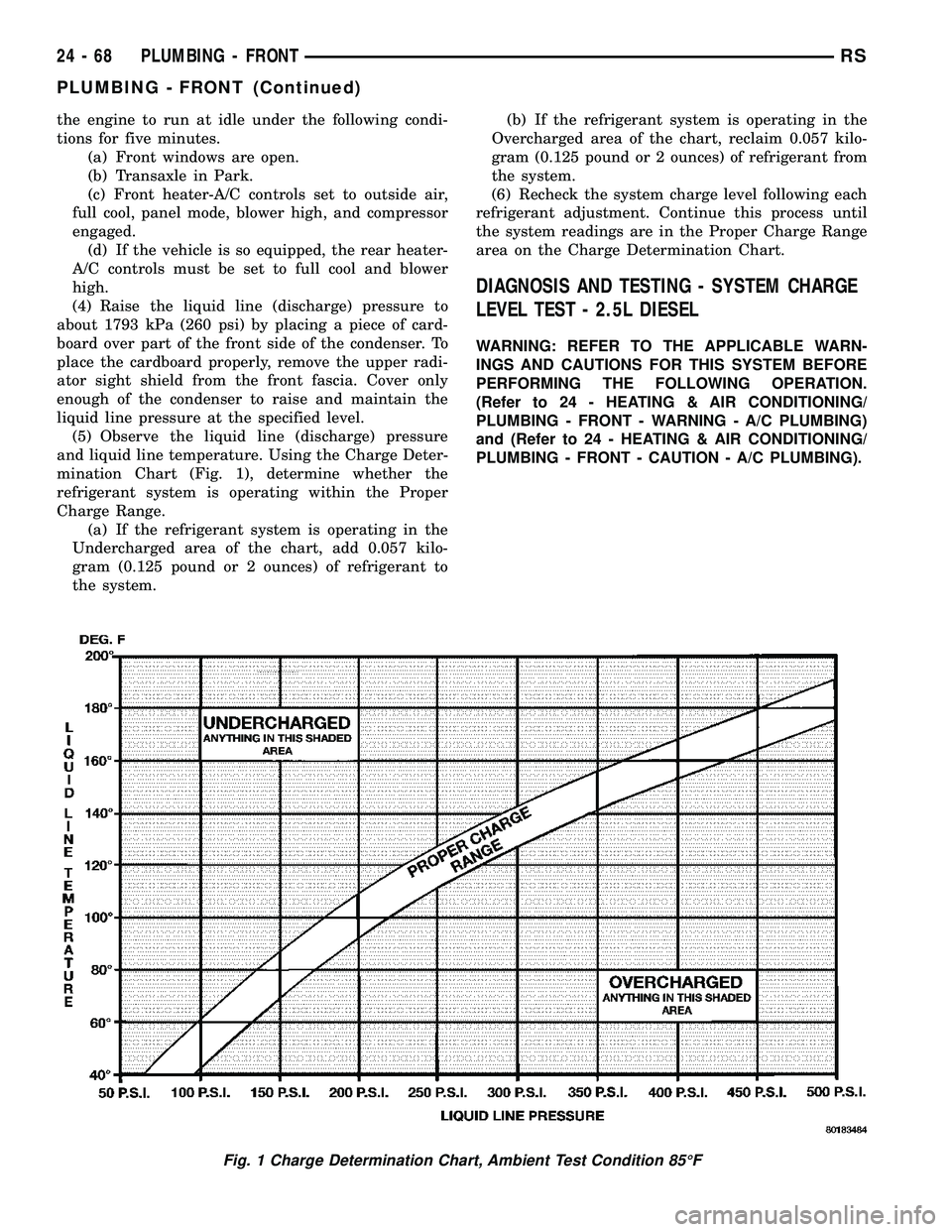
(5) Observe the liquid line (discharge) pressure
and liquid line temperature. Using the Charge Deter-
mination Chart (Fig. 1), determine whether the
refrigerant system is operating within the Proper
Charge Range.
(a) If the refrigerant system is operating in the
Undercharged area of the chart, add 0.057 kilo-
gram (0.125 pound or 2 ounces) of refrigerant to
the system.(b) If the refrigerant system is operating in the
Overcharged area of the chart, reclaim 0.057 kilo-
gram (0.125 pound or 2 ounces) of refrigerant from
the system.
(6) Recheck the system charge level following each
refrigerant adjustment. Continue this process until
the system readings are in the Proper Charge Range
area on the Charge Determination Chart.
DIAGNOSIS AND TESTING - SYSTEM CHARGE
LEVEL TEST - 2.5L DIESEL
WARNING: REFER TO THE APPLICABLE WARN-
INGS AND CAUTIONS FOR THIS SYSTEM BEFORE
PERFORMING THE FOLLOWING OPERATION.
(Refer to 24 - HEATING & AIR CONDITIONING/
PLUMBING - FRONT - WARNING - A/C PLUMBING)
and (Refer to 24 - HEATING & AIR CONDITIONING/
PLUMBING - FRONT - CAUTION - A/C PLUMBING).
Fig. 1 Charge Determination Chart, Ambient Test Condition 85ÉF
24 - 68 PLUMBING - FRONTRS
PLUMBING - FRONT (Continued)