2004 CHRYSLER VOYAGER psi
[x] Cancel search: psiPage 2465 of 2585
tion that meets SAE Standard J2210 to the refriger-
ant system.
(2) Attach a clamp-on thermocouple to the liquid
line. The thermocouple must be placed as close to the
A/C pressure transducer as possible to accurately
observe liquid line temperature.
(3) Bring the refrigerant system up to operating
temperature and pressure. This is done by allowing
the engine to run at idle under the following condi-
tions for five minutes.
(a) Front windows are open.
(b) Transaxle in Park.
(c) Front heater-A/C controls set to outside air,
full cool, panel mode, blower high, and compressor
engaged.
(d) If the vehicle is so equipped, the rear heater-
A/C controls must be set to full cool and blower
high.
(4) Raise the liquid line (discharge) pressure to
about 1793 kPa (260 psi) by placing a piece of card-
board over part of the front side of the condenser. To
place the cardboard properly, remove the upper radi-
ator sight shield from the front fascia. Cover only
enough of the condenser to raise and maintain the
liquid line pressure at the specified level.
(5) Observe the liquid line (discharge) pressure
and liquid line temperature. Using the Charge Deter-
mination Chart (Fig. 2), determine whether the
refrigerant system is operating within the Proper
Charge Range.
(a) If the refrigerant system is operating in the
Undercharged area of the chart, add 0.057 kilo-
gram (0.125 pound or 2 ounces) of refrigerant to
the system.
(b) If the refrigerant system is operating in the
Overcharged area of the chart, reclaim 0.057 kilo-
gram (0.125 pound or 2 ounces) of refrigerant from
the system.
(6) Recheck the system charge level following each
refrigerant adjustment. Continue this process until
the system readings are in the Proper Charge Range
area on the Charge Determination Chart (Fig. 2).
STANDARD PROCEDURE
STANDARD PROCEDURE - HANDLING TUBING
AND FITTINGS
CAUTION: The system must be completely empty
before opening any fitting or connection in the
refrigeration system. Open fittings with caution
even after the system has been emptied. If any
pressure is noticed as a fitting is loosened,
retighten fitting and evacuate the system again.
A good rule for the flexible hose lines is to keep theradius of all bends at least 10 times the diameter of
the hose. Sharper bends will reduce the flow of
refrigerant. The flexible hose lines should be routed
so they are at least 3 inches (80 mm) from the
exhaust manifold. Inspect all flexible hose lines to
make sure they are in good condition and properly
routed.
The use of correct wrenches when making connec-
tions is very important. Improper wrenches or
improper use of wrenches can damage the fittings.
The internal parts of the A/C system will remain sta-
ble as long as moisture-free refrigerant and refrig-
erant oil is used. Abnormal amounts of dirt,
moisture or air can upset the chemical stability.
This may cause operational troubles or even seri-
ous damage if present in more than very small
quantities. Before disconnecting a component,
clean the outside of the fittings thoroughly to pre-
vent contamination from entering the refrigerant
system.
When opening a refrigeration system, have every-
thing you will need to repair the system ready. This
will minimize the amount of time the system must
be opened. Cap or plug all lines and fittings as
soon as they are opened. This will help prevent the
entrance of dirt and moisture. All new lines and
components should be capped or sealed until they
are ready to be used. Before connecting a compo-
nent, clean the outside of the fittings thoroughly to
prevent contamination from entering the refrigerant
system.
All tools, including the refrigerant dispensing mani-
fold, the manifold gauge set, and test hoses should
be kept clean and dry.
Kinks in the refrigerant tubing or sharp bends in
the refrigerant hose lines will greatly reduce the
capacity of the entire system. High pressures are pro-
duced in the system when it is operating. Extreme
care must be exercised to make sure that all connec-
tions are pressure tight. Dirt and moisture can enter
the system when it is opened for repair or replace-
ment of lines or components. The refrigerant oil will
absorb moisture readily out of the air. This moisture
will convert into acids within a closed system.
STANDARD PROCEDURE - REFRIGERANT
SYSTEM SERVICE EQUIPMENT
WARNING: EYE PROTECTION MUST BE WORN
WHEN SERVICING AN AIR CONDITIONING REFRIG-
ERANT SYSTEM. TURN OFF (ROTATE CLOCKWISE)
ALL VALVES ON THE EQUIPMENT BEING USED
BEFORE CONNECTING TO, OR DISCONNECTING
FROM THE REFRIGERANT SYSTEM. FAILURE TO
OBSERVE THESE WARNINGS MAY RESULT IN PER-
SONAL INJURY.
24 - 70 PLUMBING - FRONTRS
PLUMBING - FRONT (Continued)
Page 2468 of 2585

CHARGING PROCEDURE
CAUTION: A small amount of refrigerant oil is
removed from the A/C system each time the refrig-
erant system is recovered and evacuated. Before
charging the A/C system, you MUST replenish any
oil lost during the recovery process. Refer the
equipment manufacturer instructions for more infor-
mation.
(1) Evacuate the refrigerant system. (Refer to 24 -
HEATING & AIR CONDITIONING/PLUMBING -
FRONT/REFRIGERANT - STANDARD PROCE-
DURE - REFRIGERANT SYSTEM EVACUATE).
(2) A manifold gauge set and a R-134a refrigerant
recovery/recycling/charging station that meets SAE
Standard J2210 should still be connected to the
refrigerant system.
(3) Measure the proper amount of refrigerant and
heat it to 52É C (125É F) with the charging station.
See the operating instructions supplied by the equip-
ment manufacturer for proper use of this equipment.
(4) Open both the suction and discharge valves,
then open the charge valve to allow the heated
refrigerant to flow into the system.
(5) When the transfer of refrigerant has stopped,
close both the suction and discharge valves.
(6) If all of the refrigerant charge did not transfer
from the dispensing device, open all of the windows
in the vehicle and set the heater-air conditioner con-
trols so that the compressor is engaged and the
blower motor is operating at its lowest speed setting.
Run the engine at a steady high idle (about 1400
rpm). If the compressor will not engage, test the com-
pressor clutch control circuit and repair as required.
(7) Open the suction valve to allow the remaining
refrigerant to transfer to the refrigerant system.
WARNING: TAKE CARE NOT TO OPEN THE DIS-
CHARGE (HIGH PRESSURE) VALVE AT THIS TIME.
(8) Close the suction valve and test the system
performance. (Refer to 24 - HEATING & AIR CON-
DITIONING - STANDARD PROCEDURE - A/C PER-
FORMANCE TEST).
(9) Disconnect the charging station and manifold
gauge set from the refrigerant system service ports.
(10) Reinstall the caps onto the refrigerant system
service ports.
(11) Run the HVAC Control Cooldown test to ver-
ify proper operation(Refer to 24 - HEATING & AIR
CONDITIONING - DIAGNOSIS AND TESTING).A/C COMPRESSOR
DESCRIPTION
DESCRIPTION - A/C COMPRESSOR
Vehicles equipped with the 2.5L diesel, 3.3L and
3.8L gasoline engines use the Denso 10S20 A/C com-
pressor. Vehicles equipped with the 2.4L gasoline
engine use the Denso 10S17 A/C compressor. Both
A/C compressors include an integral high pressure
relief valve. The A/C compressor is secured to a
mounting bracket on the 2.4L gasoline engine and
directly to the cylinder block on the 2.5L diesel, 3.3L
and 3.8L gasoline engines.
DESCRIPTION - HIGH PRESSURE RELIEF
VALVE
A high pressure relief valve is located on the rear
of the A/C compressor. This mechanical valve is
designed to vent refrigerant from the A/C system to
protect against damage to the compressor and other
system components, caused by condenser air flow
restriction or an overcharge of refrigerant.
OPERATION
OPERATION - A/C COMPRESSOR
The A/C compressor is driven by the engine
through an electric clutch, drive pulley and belt
arrangement. The compressor is lubricated by refrig-
erant oil that is circulated throughout the refrigerant
system with the refrigerant.
The compressor draws in low-pressure refrigerant
vapor from the evaporator through its suction port. It
then compresses the refrigerant into a high-pressure,
high-temperature refrigerant vapor. The compressor
pumps the high-pressure refrigerant vapor to the
condenser through the compressor discharge port.
The compressor cannot be repaired. If faulty or
damaged, the entire compressor assembly must be
replaced. The compressor clutch, pulley and clutch
coil are available for service.
OPERATION - HIGH PRESSURE RELIEF VALVE
The high pressure relief valve vents the system
when a discharge pressure of 3445 to 4135 kPa (500
to 600 psi) or above is reached. The valve closes
when a minimum discharge pressure of 2756 kPa
(400 psi) is reached.
The high pressure relief valve vents only enough
refrigerant to reduce the system pressure, and then
re-seats itself. The majority of the refrigerant is con-
served in the system. If the valve vents refrigerant, it
does not mean that the valve is faulty.
RSPLUMBING - FRONT24-73
PLUMBING - FRONT (Continued)
Page 2476 of 2585
is fitted to the evaporator inlet and outlet tubes
where they exit the HVAC housing.
(2) Assemble the HVAC housing (Refer to 24 -
HEATING & AIR CONDITIONING/DISTRIBUTION/
HVAC HOUSING - ASSEMBLY).
(3) Install the HVAC housing (Refer to 24 - HEAT-
ING & AIR CONDITIONING/DISTRIBUTION/HVAC
HOUSING - INSTALLATION).
EXPANSION VALVE
DESCRIPTION
The front ªHº valve-type thermal expansion valve
(TXV) is located at the dash panel between the liquid
and suction lines, and the A/C evaporator. The
assembly consists of an aluminum H-valve body and
a thermal sensor. On vehicles equipped with the
automatic temperature control (ATC) heater- A/C sys-
tem, the evaporator temperature sensor is installed
on the top of the expansion valve.
OPERATION
High-pressure, low temperature liquid refrigerant
from the liquid line passes through the expansion
valve orifice, converting it into a low-pressure, low-
temperature mixture of liquid and gas before it
enters the evaporator coil. A mechanical sensor in the
expansion valve control head monitors the tempera-
ture and pressure of the refrigerant leaving the evap-
orator coil through the suction line, and adjusts the
orifice size at the liquid line to let the proper amount
of refrigerant into the evaporator coil to meet the
vehicle cooling requirements. Controlling the refriger-
ant flow through the A/C evaporator ensures that
none of the refrigerant leaving the evaporator is still
in a liquid state, which could damage the compressor.
The A/C expansion valve is a factory calibrated
unit and cannot be adjusted or repaired and, if faulty
or damaged, it must be replaced.
DIAGNOSIS AND TESTING - A/C EXPANSION
VALVE
WARNING: REFER TO THE APPLICABLE WARN-
INGS AND CAUTIONS FOR THIS SYSTEM BEFORE
PERFORMING THE FOLLOWING OPERATION (Refer
to 24 - HEATING & AIR CONDITIONING/PLUMBING -
FRONT - WARNING - A/C PLUMBING) and (Refer to
24 - HEATING & AIR CONDITIONING/PLUMBING -
FRONT - CAUTION - A/C PLUMBING).
NOTE: The A/C expansion valve should only be
tested following testing of the A/C compressor.NOTE: Liquid CO
2is required to test the A/C expan-
sion valve. This material is available from most
welding supply facilities. Liquid CO
2is also avail-
able from companies which service and sell fire
extinguishers.
When testing the A/C expansion valve, the work
area and the vehicle temperature must be 21É to 27É
C (70É to 85É F). To test the expansion valve:
(1) Connect a charging station or manifold gauge
set to the refrigerant system service ports. Verify the
refrigerant charge level.
(2) Close all doors, windows and vents to the pas-
senger compartment.
(3) Set the A/C-heater controls so that the com-
pressor is operating, the temperature control is in
the highest temperature position, the mode door is
directing the output to the floor outlets, and the
blower is operating at the highest speed setting.
(4) Start the engine and allow it to idle. After the
engine has reached normal operating temperature,
allow the passenger compartment to heat up. This
will create the need for maximum refrigerant flow
into the A/C evaporator.
(5) If the refrigerant charge is sufficient, the dis-
charge (high pressure) gauge should read 965 to 1655
kPa (140 to 240 psi). The suction (low pressure)
gauge should read 140 kPa to 207 kPa (20 psi to 30
psi). If OK, go to Step 6. If not OK, replace the faulty
A/C expansion valve.
WARNING:
PROTECT THE SKIN AND EYES FROM EXPOSURE
TO LIQUID CO
2. PERSONAL INJURY CAN RESULT.
(6) If the suction (low pressure) gauge reads
within the specified range, freeze the expansion valve
control head for 30 seconds using liquid CO
2or
another suitable super-cold material.Do not spray
R-134a or R-12 refrigerant on the expansion
valve control head for this test.The suction (low
pressure) gauge reading should drop by 10 psi. If OK,
go to Step 7 If not OK, replace the faulty A/C expan-
sion valve.
(7) Allow the expansion valve control head to thaw.
The suction (low pressure) gauge reading should sta-
bilize at 140 kPa to 240 kPa (20 psi to 30 psi). If not
OK, replace the faulty A/C expansion valve.
(8) When expansion valve testing is complete, test
the overall air conditioner performance (Refer to 24 -
HEATING & AIR CONDITIONING - DIAGNOSIS
AND TESTING - A/C PERFORMANCE TEST).
RSPLUMBING - FRONT24-81
A/C EVAPORATOR (Continued)
Page 2495 of 2585
The rear A/C expansion valve cannot be adjusted
or repaired and, if faulty or damaged, it must be
replaced.
DIAGNOSIS AND TESTING - EXPANSION VALVE
WARNING: REFER TO THE APPLICABLE WARN-
INGS AND CAUTIONS FOR THIS SYSTEM BEFORE
PERFORMING THE FOLLOWING OPERATION.
(Refer to 24 - HEATING & AIR CONDITIONING/
PLUMBING - FRONT - WARNING - A/C PLUMBING)
and (Refer to 24 - HEATING & AIR CONDITIONING/
PLUMBING - FRONT - CAUTION - A/C PLUMBING).
NOTE: The expansion valve should only be tested
following testing of the compressor.
NOTE: Liquid CO
2is required to test the expansion
valve. This material is available from most welding
supply facilities. Liquid CO
2is also available from
companies which service and sell fire extinguish-
ers.
When testing the expansion valve, the work area
and the vehicle temperature must be 21É to 27É C
(70É to 85É F). To test the expansion valve:
(1) Connect a charging station or manifold gauge
set to the refrigerant system service ports. Verify the
refrigerant charge level.
(2) Close all doors, windows and vents to the pas-
senger compartment.
(3) Set the heater-air conditioner controls so that
the compressor is operating, the temperature control
is in the highest temperature position, the mode door
is directing the output to the floor outlets, and the
blower is operating at the highest speed setting.
(4) Start the engine and allow it to idle at 1000
rpm. After the engine has reached normal operating
temperature, allow the passenger compartment to
heat up. This will create the need for maximum
refrigerant flow into the evaporator.
(5) If the refrigerant charge is sufficient, the dis-
charge (high pressure) gauge should read 965 to 1655
kPa (140 to 240 psi). The suction (low pressure)
gauge should read 140 kPa to 207 kPa (20 psi to 30
psi). If OK, go to Step 6. If not OK, replace the faulty
expansion valve.
WARNING: PROTECT THE SKIN AND EYES FROM
EXPOSURE TO LIQUID CO
2. PERSONAL INJURY
CAN RESULT.
(6) If the suction (low pressure) gauge reads
within the specified range, freeze the expansion valve
control head for 30 seconds using liquid CO
2or
another suitable super-cold material.Do not sprayR-134a or R-12 refrigerant on the expansion
valve control head for this test.The suction (low
pressure) gauge reading should drop by 10 psi. If OK,
go to Step 7 If not OK, replace the faulty expansion
valve.
(7) Allow the expansion valve control head to thaw.
The suction (low pressure) gauge reading should sta-
bilize at 140 kPa to 240 kPa (20 psi to 30 psi). If not
OK, replace the faulty expansion valve.
(8) When expansion valve testing is complete, test
the overall air conditioner performance (Refer to 24 -
HEATING & AIR CONDITIONING - DIAGNOSIS
AND TESTING - A/C PERFORMANCE TEST).
Remove all test equipment before returning the vehi-
cle to service.
REMOVAL
WARNING: REFER TO THE APPLICABLE WARN-
INGS AND CAUTIONS FOR THIS SYSTEM BEFORE
PERFORMING THE FOLLOWING OPERATION (Refer
to 24 - HEATING & AIR CONDITIONING/PLUMBING -
FRONT - WARNING - A/C PLUMBING), (Refer to 24 -
HEATING & AIR CONDITIONING/PLUMBING -
FRONT - CAUTION - A/C PLUMBING), and (Refer to
24 - HEATING & AIR CONDITIONING/PLUMBING -
FRONT - WARNING - HEATER PLUMBING).
(1) Remove the rear HVAC housing from the vehi-
cle (Refer to 24 - HEATING & AIR CONDITIONING/
DISTRIBUTION/HVAC HOUSING - REMOVAL).
(2) Carefully remove the foam insulator wrap from
the rear expansion valve.
(3) Remove the rear evaporator line extension from
the expansion valve (Refer to 24 - HEATING & AIR
CONDITIONING/PLUMBING - REAR/EVAPORA-
TOR - REMOVAL - EVAPORATOR LINE EXTEN-
SION).
(4) Remove the two screws that secure the expan-
sion valve to the evaporator tube sealing plate.
(5) Remove the expansion valve from the evapora-
tor tubes.
(6) Remove the seals from the evaporator tube fit-
tings and discard.
(7) Install plugs in, or tape over the opened evap-
orator tube fittings and both expansion valve ports.
INSTALLATION
(1) Remove the tape or plugs from the rear A/C
evaporator tube fittings and both expansion valve
ports.
(2) Lubricate new rubber O-ring seals with clean
refrigerant oil and install them on the rear evapora-
tor tube fittings.
(3) Position the expansion valve onto the evapora-
tor tubes.
24 - 100 PLUMBING - REARRS
A/C EXPANSION VALVE (Continued)
Page 2518 of 2585
ªBig Slopeº. The PCM checks the oxygen sensor volt-
age in increments of a few milliseconds.
Reduced Output Voltage (Half Cycle)ÐThe
output voltage of the O2S ranges from 0 to 1 volt
(voltages are offset by 2.5 volts on NGC vehicles). A
good sensor can easily generate any output voltage in
this range as it is exposed to different concentrations
of oxygen. To detect a shift in the A/F mixture (lean
or rich), the output voltage has to change beyond a
threshold value. A malfunctioning sensor could have
difficulty changing beyond the threshold value. Each
time the voltage signal surpasses the threshold, a
counter is incremented by one. This is called the Half
Cycle Counter.
Heater PerformanceÐThe heater is tested by a
separate monitor. Refer to the Oxygen Sensor Heater
Monitor.
OPERATIONÐAs the Oxygen Sensor signal
switches, the PCM monitors the half cycle and big
slope signals from the oxygen sensor. If during the
test neither counter reaches a predetermined value, a
malfunction is entered and Freeze Frame data is
stored. Only one counter reaching its predetermined
value is needed for the monitor to pass.
The Oxygen Sensor Monitor is a two trip monitor
that is tested only once per trip. When the Oxygen
Sensor fails the test in two consecutive trips, the
MIL is illuminated and a DTC is set. The MIL is
extinguished when the Oxygen Sensor monitor
passes in three consecutive trips. The DTC is erased
from memory after 40 consecutive warm-up cycles
without test failure.
Enabling ConditionsÐThe following conditions
must typically be met for the PCM to run the oxygen
sensor monitor:
²Battery voltage
²Engine temperature
²Engine run time
²Engine run time at a predetermined speed
²Engine run time at a predetermined speed and
throttle opening
²Transmission in gear and brake depressed (auto-
matic only)
²Fuel system in Closed Loop
²Long Term Adaptive (within parameters)
²Power Steering Switch in low PSI (no load)
²Engine at idle
²Fuel level above 15%
²Ambient air temperature
²Barometric pressure
²Engine RPM within acceptable range of desired
idle
Pending ConditionsÐThe Task Manager typi-
cally does not run the Oxygen Sensor Monitor if over-
lapping monitors are running or the MIL is
illuminated for any of the following:²Misfire Monitor
²Front Oxygen Sensor and Heater Monitor
²MAP Sensor
²Vehicle Speed Sensor
²Engine Coolant Temperature Sensor
²Throttle Position Sensor
²Engine Controller Self Test Faults
²Cam or Crank Sensor
²Injector and Coil
²Idle Air Control Motor
²EVAP Electrical
²EGR Solenoid Electrical (if equipped)
²Intake/inlet Air Temperature
²5 Volt Feed
ConflictÐThe Task Manager does not run the
Oxygen Sensor Monitor if any of the following condi-
tions are present:
²A/C ON (A/C clutch cycling temporarily sus-
pends monitor)
²Purge flow in progress
²Ethanol content learn is taking place and the
ethanol used once flag is set (if equipped)
SuspendÐThe Task Manager suspends maturing
a fault for the Oxygen Sensor Monitor if any of the
following are present:
²Oxygen Sensor Heater Monitor, Priority 1
²Misfire Monitor, Priority 2
OXYGEN SENSOR HEATER MONITOR
DESCRIPTIONÐIf there is an oxygen sensor
(O2S) DTC as well as a O2S heater DTC, the O2S
fault MUST be repaired first. After the O2S fault is
repaired, verify that the heater circuit is operating
correctly.
The voltage readings taken from the O2S are very
temperature sensitive. The readings are not accurate
below a sensor temperature of 300ÉC. Heating of the
O2S is done to allow the engine controller to shift to
closed loop control as soon as possible. The heating
element used to heat the O2S must be tested to
ensure that it is heating the sensor properly.
The heater element itself is not tested. The sensor
output is used to test the heater by isolating the
effect of the heater element on the O2S output volt-
age from the other effects. The resistance is normally
between 100 ohms and 4.5 megaohms. When oxygen
sensor temperature increases, the resistance in the
internal circuit decreases. The PCM sends a 5 volts
biased signal through the oxygen sensors to ground
this monitoring circuit. As the temperature increases,
resistance decreases and the PCM detects a lower
voltage at the reference signal. Inversely, as the tem-
perature decreases, the resistance increases and the
PCM detects a higher voltage at the reference signal.
The O2S circuit is monitored for a drop in voltage.
RSEMISSIONS CONTROL25-3
EMISSIONS CONTROL (Continued)
Page 2527 of 2585
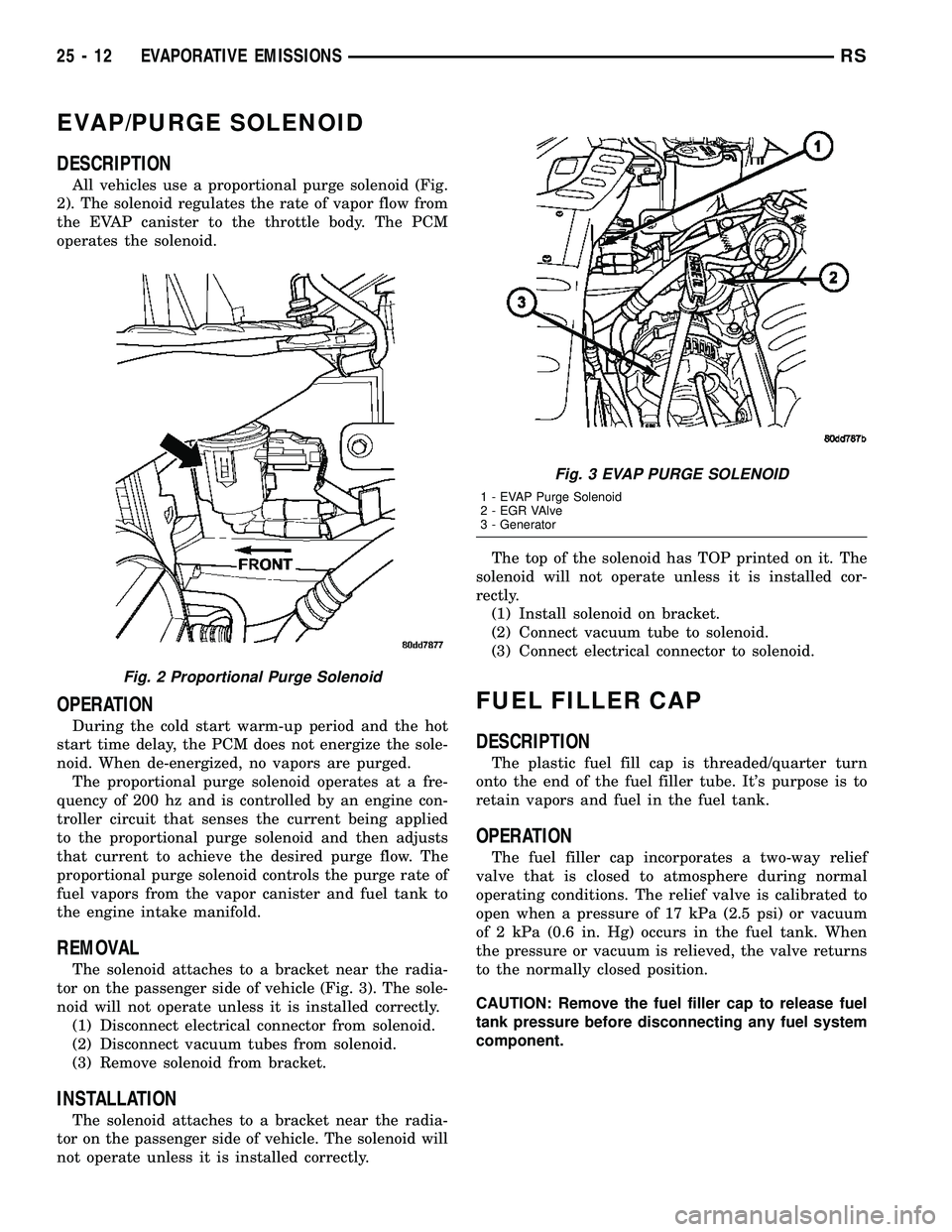
EVAP/PURGE SOLENOID
DESCRIPTION
All vehicles use a proportional purge solenoid (Fig.
2). The solenoid regulates the rate of vapor flow from
the EVAP canister to the throttle body. The PCM
operates the solenoid.
OPERATION
During the cold start warm-up period and the hot
start time delay, the PCM does not energize the sole-
noid. When de-energized, no vapors are purged.
The proportional purge solenoid operates at a fre-
quency of 200 hz and is controlled by an engine con-
troller circuit that senses the current being applied
to the proportional purge solenoid and then adjusts
that current to achieve the desired purge flow. The
proportional purge solenoid controls the purge rate of
fuel vapors from the vapor canister and fuel tank to
the engine intake manifold.
REMOVAL
The solenoid attaches to a bracket near the radia-
tor on the passenger side of vehicle (Fig. 3). The sole-
noid will not operate unless it is installed correctly.
(1) Disconnect electrical connector from solenoid.
(2) Disconnect vacuum tubes from solenoid.
(3) Remove solenoid from bracket.
INSTALLATION
The solenoid attaches to a bracket near the radia-
tor on the passenger side of vehicle. The solenoid will
not operate unless it is installed correctly.The top of the solenoid has TOP printed on it. The
solenoid will not operate unless it is installed cor-
rectly.
(1) Install solenoid on bracket.
(2) Connect vacuum tube to solenoid.
(3) Connect electrical connector to solenoid.
FUEL FILLER CAP
DESCRIPTION
The plastic fuel fill cap is threaded/quarter turn
onto the end of the fuel filler tube. It's purpose is to
retain vapors and fuel in the fuel tank.
OPERATION
The fuel filler cap incorporates a two-way relief
valve that is closed to atmosphere during normal
operating conditions. The relief valve is calibrated to
open when a pressure of 17 kPa (2.5 psi) or vacuum
of 2 kPa (0.6 in. Hg) occurs in the fuel tank. When
the pressure or vacuum is relieved, the valve returns
to the normally closed position.
CAUTION: Remove the fuel filler cap to release fuel
tank pressure before disconnecting any fuel system
component.
Fig. 2 Proportional Purge Solenoid
Fig. 3 EVAP PURGE SOLENOID
1 - EVAP Purge Solenoid
2 - EGR VAlve
3 - Generator
25 - 12 EVAPORATIVE EMISSIONSRS