2004 CHRYSLER VOYAGER psi
[x] Cancel search: psiPage 1889 of 2585
The process of elimination can be used to detect
any unit which slips and to confirm proper operation
of good units. Road test analysis can diagnose slip-
ping units, but the cause of the malfunction cannot
be determined. Practically any condition can be
caused by leaking hydraulic circuits or sticking
valves.
DIAGNOSIS AND TESTING - HYDRAULIC
PRESSURE TESTS
Pressure testing is a very important step in the
diagnostic procedure. These tests usually reveal the
cause of most hydraulic transaxle problems. Before performing pressure tests, be certain that
fluid level and condition, and shift cable adjustments
have been checked and approved. Fluid must be at
operating temperature (150 to 200 degrees F.). Install an engine tachometer, raise vehicle on hoist
which allows front wheels to turn, and position
tachometer so it can be read. Attach 300 psi gauge (C-3293SP) to port(s)
required for test(s) being conducted. Use adapter set
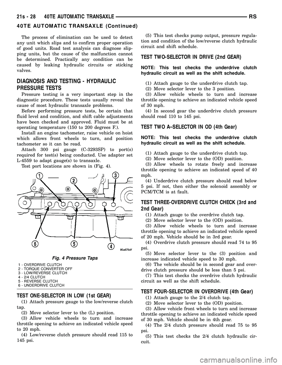
L-4559 to adapt gauge(s) to transaxle. Test port locations are shown in (Fig. 4).
TEST ONE-SELECTOR IN LOW (1st GEAR)
(1) Attach pressure gauge to the low/reverse clutch
tap. (2) Move selector lever to the (L) position.
(3) Allow vehicle wheels to turn and increase
throttle opening to achieve an indicated vehicle speed
to 20 mph. (4) Low/reverse clutch pressure should read 115 to
145 psi. (5) This test checks pump output, pressure regula-
tion and condition of the low/reverse clutch hydraulic
circuit and shift schedule.
TEST TWO-SELECTOR IN DRIVE (2nd GEAR)
NOTE: This test checks the underdrive clutch
hydraulic circuit as well as the shift schedule.
(1) Attach gauge to the underdrive clutch tap.
(2) Move selector lever to the 3 position.
(3) Allow vehicle wheels to turn and increase
throttle opening to achieve an indicated vehicle speed
of 30 mph. (4) In second gear the underdrive clutch pressure
should read 110 to 145 psi.
TEST TWO A±SELECTOR IN OD (4th Gear)
NOTE: This test checks the underdrive clutch
hydraulic circuit as well as the shift schedule.
(1) Attach gauge to the underdrive clutch tap.
(2) Move selector lever to the (OD) position.
(3) Allow wheels to rotate freely and increase
throttle opening to achieve an indicated speed of 40
mph. (4) Underdrive clutch pressure should read below
5 psi. If not, then either the solenoid assembly or
PCM/TCM is at fault.
TEST THREE-OVERDRIVE CLUTCH CHECK (3rd and
2nd Gear)
(1) Attach gauge to the overdrive clutch tap.
(2) Move selector lever to the (OD) position.
(3) Allow vehicle wheels to turn and increase
throttle opening to achieve an indicated vehicle speed
of 20 mph. Vehicle should be in 3rd gear. (4) Overdrive clutch pressure should read 74 to 95
psi. (5) Move selector lever to the (3) position and
increase indicated vehicle speed to 30 mph. (6) The vehicle should be in second gear and over-
drive clutch pressure should be less than 5 psi. (7) This test checks the overdrive clutch hydraulic
circuit as well as the shift schedule.
TEST FOUR-SELECTOR IN OVERDRIVE (4th Gear)
(1) Attach gauge to the 2/4 clutch tap.
(2) Move selector lever to the (OD) position.
(3) Allow vehicle front wheels to turn and increase
throttle opening to achieve an indicated vehicle speed
of 30 mph. Vehicle should be in 4th gear. (4) The 2/4 clutch pressure should read 75 to 95
psi. (5) This test checks the 2/4 clutch hydraulic cir-
cuit.
Fig. 4 Pressure Taps
1 - OVERDRIVE CLUTCH
2 - TORQUE CONVERTER OFF
3 - LOW/REVERSE CLUTCH
4 - 2/4 CLUTCH
5 - REVERSE CLUTCH
6 - UNDERDRIVE CLUTCH
21s - 28 40TE AUTOMATIC TRANSAXLERS
40TE AUTOMATIC TRANSAXLE (Continued)
Page 1890 of 2585
TEST FIVE-SELECTOR IN OVERDRIVE (4th Gear-CC
on)
(1) Attach gauge to the torque converter clutch off
pressure tap. (2) Move selector lever to the (OD) position.
(3) Allow vehicle wheels to turn and increase
throttle opening to achieve an indicated vehicle speed
of 50 mph. Vehicle should be in 4th gear, CC on.
CAUTION: Both wheels must turn at the same
speed.
(4) Torque converter clutch off pressure should be
less than 5 psi. (5) This test checks the torque converter clutch
hydraulic circuit.
TEST SIX-SELECTOR IN REVERSE
(1) Attach gauges to the reverse and LR clutch
tap. (2) Move selector lever to the (R) position.
(3) Read reverse clutch pressure with output sta-
tionary (foot on brake) and throttle opened to achieve
1500 rpm. (4) Reverse and LR clutch pressure should read
165 to 235 psi. (5) This test checks the reverse clutch hydraulic
circuit.
TEST RESULT INDICATIONS
(1) If proper line pressure is found in any one test,
the pump and pressure regulator are working prop-
erly. (2) Low pressure in all positions indicates a defec-
tive pump, a clogged filter, or a stuck pressure regu-
lator valve. (3) Clutch circuit leaks are indicated if pressures
do not fall within the specified pressure range. (4) If the overdrive clutch pressure is greater than
5 psi in Step 4 of Test Three, a worn reaction shaft
seal ring or a defective solenoid assembly is indi-
cated. (5) If the underdrive clutch pressure is greater
than 5 psi in Step 4 of Test Two A, a defective sole-
noid assembly or PCM/TCM is the cause.
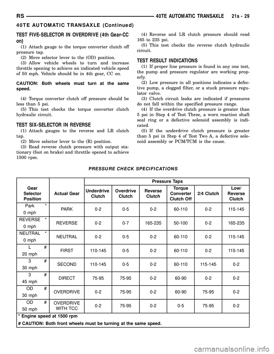
PRESSURE CHECK SPECIFICATIONS
Pressure Taps
Gear
Selector
Position Actual Gear
Underdrive
Clutch Overdrive
Clutch Reverse
Clutch Torque
Converter
Clutch Off 2/4 Clutch Low/
Reverse Clutch
Park * PARK 0-2 0-5 0-2 60-110 0-2 115-145
0 mph
REVERSE * REVERSE 0-2 0-7 165-235 50-100 0-2 165-235
0 mph
NEUTRAL * NEUTRAL 0-2 0-5 0-2 60-110 0-2 115-145
0 mph
L# FIRST 110-145 0-5 0-2 60-110 0-2 115-145
20 mph
3# SECOND 110-145 0-5 0-2 60-110 115-145 0-2
30 mph
3# DIRECT 75-95 75-95 0-2 60-90 0-2 0-2
45 mph
OD # OVERDRIVE 0-2 75-95 0-2 60-90 75-95 0-2
30 mph
OD # OVERDRIVE
WITH TCC 0-2 75-95 0-2 0-5 75-95 0-2
50 mph
* Engine speed at 1500 rpm
# CAUTION: Both front wheels must be turning at the same speed.
RS 40TE AUTOMATIC TRANSAXLE21s-29
40TE AUTOMATIC TRANSAXLE (Continued)
Page 1891 of 2585
DIAGNOSIS AND TESTING - CLUTCH AIR
PRESSURE TESTS
Inoperative clutches can be located using a series
of tests by substituting air pressure for fluid pressure
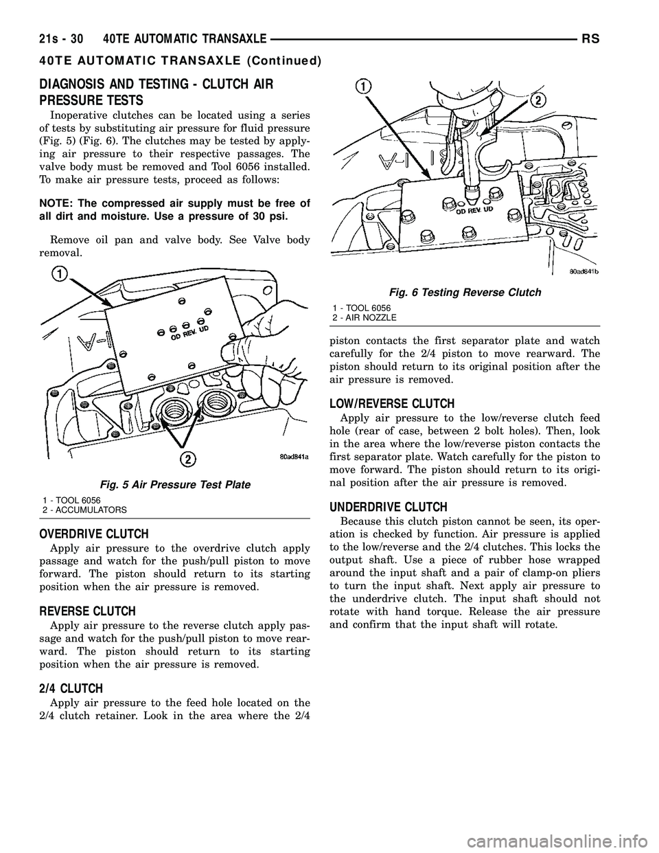
(Fig. 5) (Fig. 6). The clutches may be tested by apply-
ing air pressure to their respective passages. The
valve body must be removed and Tool 6056 installed.
To make air pressure tests, proceed as follows:
NOTE: The compressed air supply must be free of
all dirt and moisture. Use a pressure of 30 psi.
Remove oil pan and valve body. See Valve body
removal.
OVERDRIVE CLUTCH
Apply air pressure to the overdrive clutch apply
passage and watch for the push/pull piston to move
forward. The piston should return to its starting
position when the air pressure is removed.
REVERSE CLUTCH
Apply air pressure to the reverse clutch apply pas-
sage and watch for the push/pull piston to move rear-
ward. The piston should return to its starting
position when the air pressure is removed.
2/4 CLUTCH
Apply air pressure to the feed hole located on the
2/4 clutch retainer. Look in the area where the 2/4 piston contacts the first separator plate and watch
carefully for the 2/4 piston to move rearward. The
piston should return to its original position after the
air pressure is removed.
LOW/REVERSE CLUTCH
Apply air pressure to the low/reverse clutch feed
hole (rear of case, between 2 bolt holes). Then, look
in the area where the low/reverse piston contacts the
first separator plate. Watch carefully for the piston to
move forward. The piston should return to its origi-
nal position after the air pressure is removed.
UNDERDRIVE CLUTCH
Because this clutch piston cannot be seen, its oper-
ation is checked by function. Air pressure is applied
to the low/reverse and the 2/4 clutches. This locks the
output shaft. Use a piece of rubber hose wrapped
around the input shaft and a pair of clamp-on pliers
to turn the input shaft. Next apply air pressure to
the underdrive clutch. The input shaft should not
rotate with hand torque. Release the air pressure
and confirm that the input shaft will rotate.
Fig. 5 Air Pressure Test Plate
1 - TOOL 6056
2 - ACCUMULATORS
Fig. 6 Testing Reverse Clutch
1 - TOOL 6056
2 - AIR NOZZLE
21s - 30 40TE AUTOMATIC TRANSAXLERS
40TE AUTOMATIC TRANSAXLE (Continued)
Page 1984 of 2585
(15) Install input clutch assembly to the Input
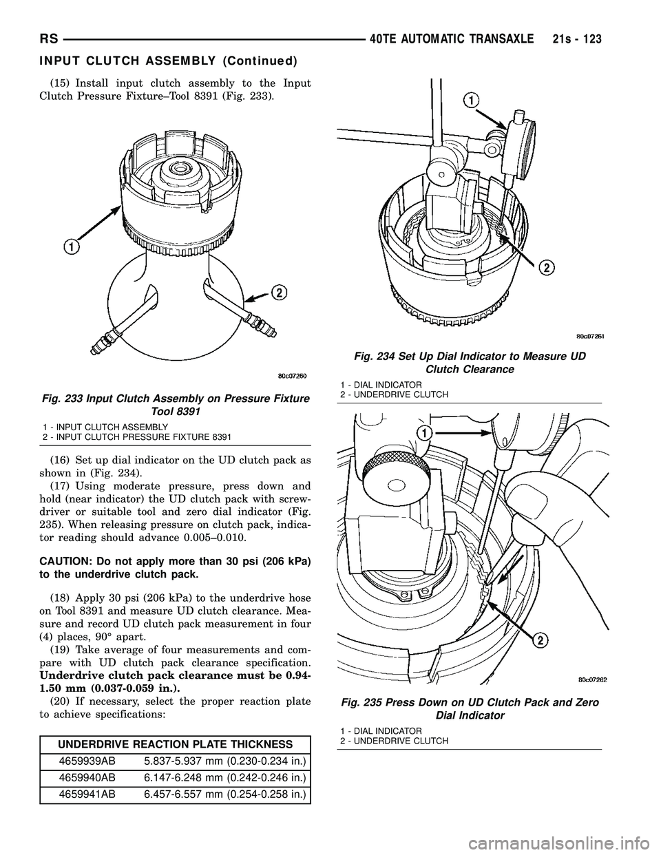
Clutch Pressure Fixture±Tool 8391 (Fig. 233).
(16) Set up dial indicator on the UD clutch pack as
shown in (Fig. 234). (17) Using moderate pressure, press down and
hold (near indicator) the UD clutch pack with screw-
driver or suitable tool and zero dial indicator (Fig.
235). When releasing pressure on clutch pack, indica-
tor reading should advance 0.005±0.010.
CAUTION: Do not apply more than 30 psi (206 kPa)
to the underdrive clutch pack.
(18) Apply 30 psi (206 kPa) to the underdrive hose
on Tool 8391 and measure UD clutch clearance. Mea-
sure and record UD clutch pack measurement in four
(4) places, 90É apart. (19) Take average of four measurements and com-
pare with UD clutch pack clearance specification.
Underdrive clutch pack clearance must be 0.94-
1.50 mm (0.037-0.059 in.). (20) If necessary, select the proper reaction plate
to achieve specifications:
UNDERDRIVE REACTION PLATE THICKNESS
4659939AB 5.837-5.937 mm (0.230-0.234 in.)
4659940AB 6.147-6.248 mm (0.242-0.246 in.)
4659941AB 6.457-6.557 mm (0.254-0.258 in.)
Fig. 233 Input Clutch Assembly on Pressure Fixture Tool 8391
1 - INPUT CLUTCH ASSEMBLY
2 - INPUT CLUTCH PRESSURE FIXTURE 8391
Fig. 234 Set Up Dial Indicator to Measure UDClutch Clearance
1 - DIAL INDICATOR
2 - UNDERDRIVE CLUTCH
Fig. 235 Press Down on UD Clutch Pack and Zero Dial Indicator
1 - DIAL INDICATOR
2 - UNDERDRIVE CLUTCH
RS 40TE AUTOMATIC TRANSAXLE21s - 123
INPUT CLUTCH ASSEMBLY (Continued)
Page 1987 of 2585
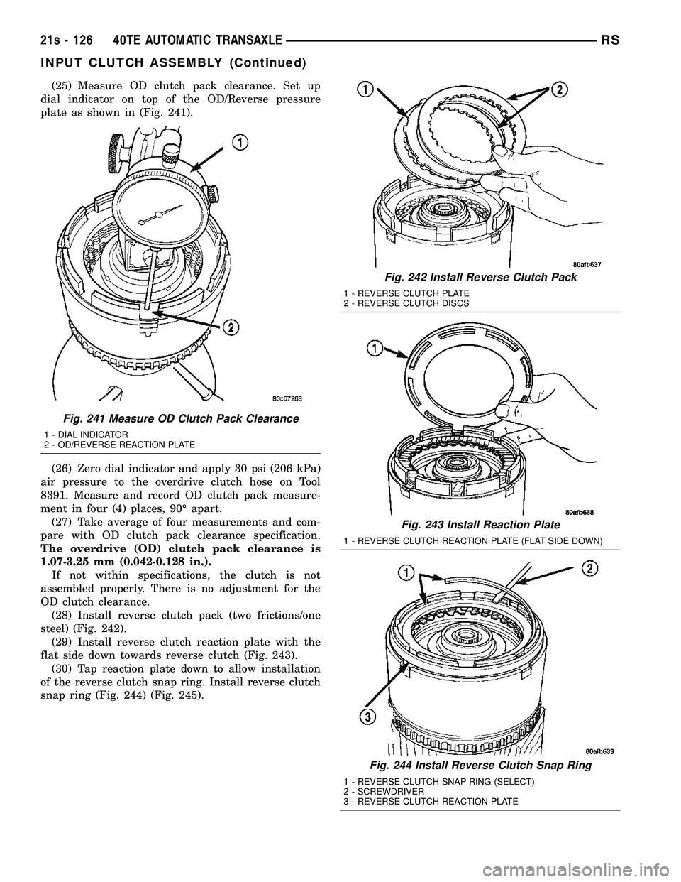
(25) Measure OD clutch pack clearance. Set up
dial indicator on top of the OD/Reverse pressure
plate as shown in (Fig. 241).
(26) Zero dial indicator and apply 30 psi (206 kPa)
air pressure to the overdrive clutch hose on Tool
8391. Measure and record OD clutch pack measure-
ment in four (4) places, 90É apart. (27) Take average of four measurements and com-
pare with OD clutch pack clearance specification.
The overdrive (OD) clutch pack clearance is
1.07-3.25 mm (0.042-0.128 in.). If not within specifications, the clutch is not
assembled properly. There is no adjustment for the
OD clutch clearance. (28) Install reverse clutch pack (two frictions/one
steel) (Fig. 242). (29) Install reverse clutch reaction plate with the
flat side down towards reverse clutch (Fig. 243). (30) Tap reaction plate down to allow installation
of the reverse clutch snap ring. Install reverse clutch
snap ring (Fig. 244) (Fig. 245).
Fig. 241 Measure OD Clutch Pack Clearance
1 - DIAL INDICATOR
2 - OD/REVERSE REACTION PLATE
Fig. 242 Install Reverse Clutch Pack
1 - REVERSE CLUTCH PLATE
2 - REVERSE CLUTCH DISCS
Fig. 243 Install Reaction Plate
1 - REVERSE CLUTCH REACTION PLATE (FLAT SIDE DOWN)
Fig. 244 Install Reverse Clutch Snap Ring
1 - REVERSE CLUTCH SNAP RING (SELECT)
2 - SCREWDRIVER
3 - REVERSE CLUTCH REACTION PLATE
21s - 126 40TE AUTOMATIC TRANSAXLERS
INPUT CLUTCH ASSEMBLY (Continued)
Page 1989 of 2585
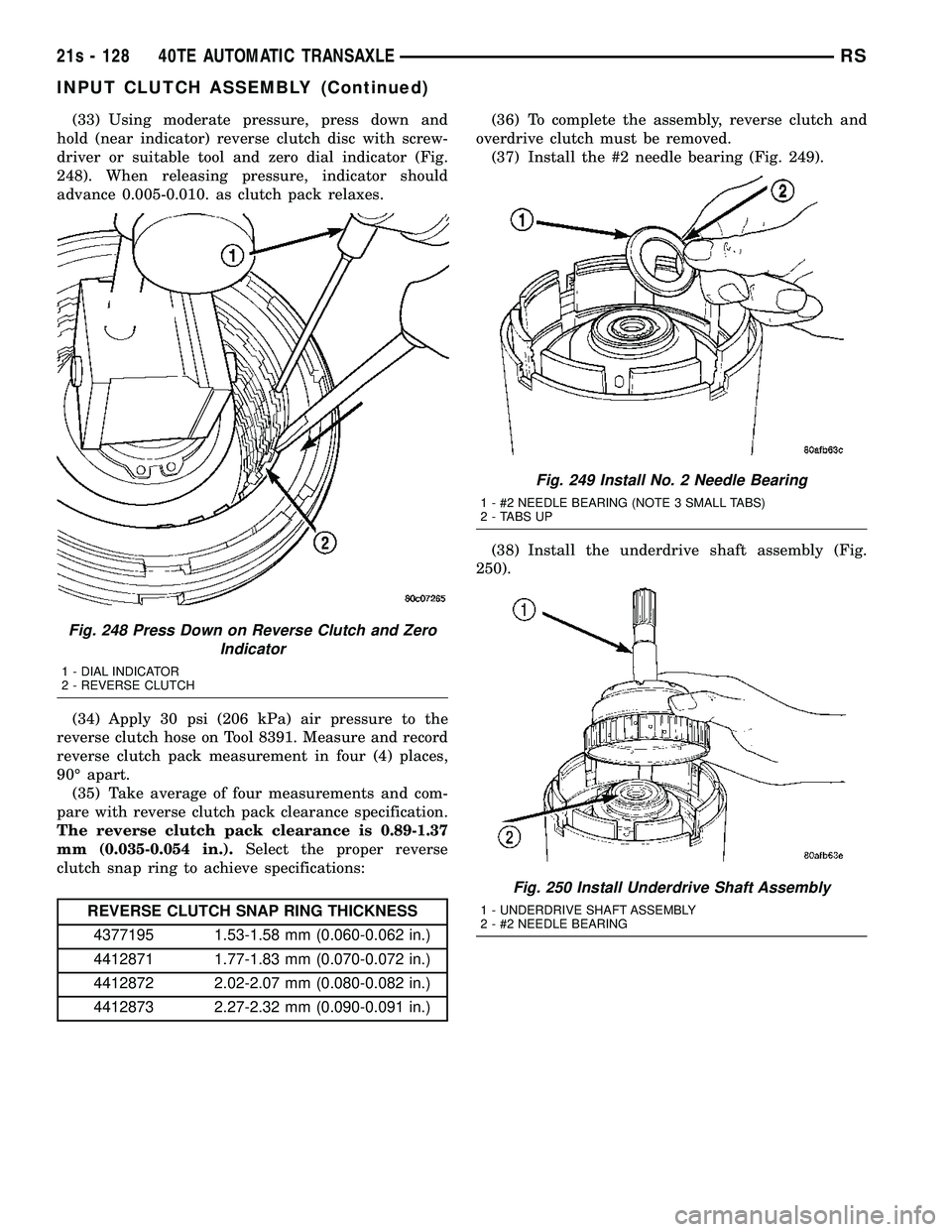
(33) Using moderate pressure, press down and
hold (near indicator) reverse clutch disc with screw-
driver or suitable tool and zero dial indicator (Fig.
248). When releasing pressure, indicator should
advance 0.005-0.010. as clutch pack relaxes.
(34) Apply 30 psi (206 kPa) air pressure to the
reverse clutch hose on Tool 8391. Measure and record
reverse clutch pack measurement in four (4) places,
90É apart. (35) Take average of four measurements and com-
pare with reverse clutch pack clearance specification.
The reverse clutch pack clearance is 0.89-1.37
mm (0.035-0.054 in.). Select the proper reverse
clutch snap ring to achieve specifications:
REVERSE CLUTCH SNAP RING THICKNESS
4377195 1.53-1.58 mm (0.060-0.062 in.)
4412871 1.77-1.83 mm (0.070-0.072 in.)
4412872 2.02-2.07 mm (0.080-0.082 in.)
4412873 2.27-2.32 mm (0.090-0.091 in.) (36) To complete the assembly, reverse clutch and
overdrive clutch must be removed. (37) Install the #2 needle bearing (Fig. 249).
(38) Install the underdrive shaft assembly (Fig.
250).
Fig. 248 Press Down on Reverse Clutch and Zero Indicator
1 - DIAL INDICATOR
2 - REVERSE CLUTCH
Fig. 249 Install No. 2 Needle Bearing
1 - #2 NEEDLE BEARING (NOTE 3 SMALL TABS)
2 - TABS UP
Fig. 250 Install Underdrive Shaft Assembly
1 - UNDERDRIVE SHAFT ASSEMBLY
2 - #2 NEEDLE BEARING
21s - 128 40TE AUTOMATIC TRANSAXLERS
INPUT CLUTCH ASSEMBLY (Continued)
Page 1999 of 2585
should be detected by the PCM/TCM during this test.
It no spike is detected, the circuit is tested again to
verify the failure. In addition to the periodic testing,
the solenoid circuits are tested if a speed ratio or
pressure switch error occurs.
PRESSURE SWITCHES
The PCM/TCM relies on three pressure switches to
monitor fluid pressure in the L/R, 2/4, and OD
hydraulic circuits. The primary purpose of these
switches is to help the PCM/TCM detect when clutch
circuit hydraulic failures occur. The range for the
pressure switch closing and opening points is 11-23
psi. Typically the switch opening point will be
approximately one psi lower than the closing point.
For example, a switch may close at 18 psi and open
at 17 psi. The switches are continuously monitored
by the PCM/TCM for the correct states (open or
closed) in each gear as shown in the following chart:
PRESSURE SWITCH STATES
GEAR L/R 2/4 OD
ROPOPOP
P/N CL OP OP 1st CL OP OP
2nd OP CL OP DOPOPCL
OD OP CL CL OP = OPEN
CL = CLOSED
A Diagnostic Trouble Code (DTC) will set if the
PCM/TCM senses any switch open or closed at the
wrong time in a given gear. The PCM/TCM also tests the 2/4 and OD pressure
switches when they are normally off (OD and 2/4 are
tested in 1st gear, OD in 2nd gear, and 2/4 in 3rd
gear). The test simply verifies that they are opera-
tional, by looking for a closed state when the corre-
sponding element is applied. Immediately after a
shift into 1st, 2nd, or 3rd gear with the engine speed
above 1000 rpm, the PCM/TCM momentarily turns
on element pressure to the 2/4 and/or OD clutch cir-
cuits to identify that the appropriate switch has
closed. If it doesn't close, it is tested again. If the
switch fails to close the second time, the appropriate
Diagnostic Trouble Code (DTC) will set.
REMOVAL
NOTE: If solenoid/pressure switch assembly is
being replaced, it is necessary to perform the TCM
Quick Learn Procedure. (Refer t o 8 - ELECTRICAL/
ELECTRONIC CONTROL MODULES/TRANSMISSION
CONTROL MODULE - STANDARD PROCEDURE)
(1) Disconnect battery negative cable.
(2) Remove air cleaner assembly.
(3) Disconnect solenoid/pressure switch assembly
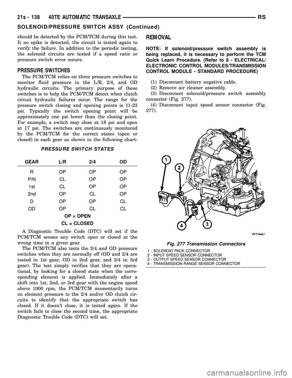
connector (Fig. 277). (4) Disconnect input speed sensor connector (Fig.
277).
Fig. 277 Transmission Connectors
1 - SOLENOID PACK CONNECTOR
2 - INPUT SPEED SENSOR CONNECTOR
3 - OUTPUT SPEED SENSOR CONNECTOR
4 - TRANSMISSION RANGE SENSOR CONNECTOR
21s - 138 40TE AUTOMATIC TRANSAXLERS
SOLENOID/PRESSURE SWITCH ASSY (Continued)
Page 2089 of 2585
If a road tire is replaced by the spare, the TPM
system will detect the swap and the message9SPARE
TIRE IN USE? Y/N9(along with a chime) will be dis-
played.
For further information, refer to the Owners Man-
ual or the Appropriate Diagnostic Information.
TPM THRESHOLD PRESSURES
High Pressure ON Threshold 48 PSI (331 kPa)
High Pressure OFF Threshold 43 PSI (296 kPa)
Placard Pressure (Cold) 36 PSI (248 kPa)
Low Pressure OFF Threshold 33 PSI (228 kPa)
Low Pressure ON Threshold 28 PSI (193 kPa)
SENSOR - TPM
DESCRIPTION
On vehicles equipped with Tire Pressure Monitor-
ing, one tire pressure sensor is mounted to each
wheel (Fig. 19). Each sensor has an internal battery
that lasts up to 10 years. The battery is not service-
able. At the time of battery failure, the sensor must
be replaced. The serviceable components of the tire
pressure sensor are:
²Sensor-To-Wheel Grommet
²Valve Stem Cap
²Valve Stem Core
Valve stem caps and cores are specifically designed
for the tire pressure monitoring sensors. Although
similar to standard valve stem caps and cores, they
are different.
CAUTION: Do not use a standard valve stem cap or
core in a tire pressure sensor. Always use the orig-
inal equipment style sensor cap and core.
CAUTION: Do not reuse the Sensor-To Wheel Grom-
met. Always use a new grommet when installing a
pressure sensor and properly torque the sensor
nut.
CAUTION: Do not try to install a tire pressure sen-
sor in a steel wheel or aftermarket wheel. Use only
in original style factory wheels.
OPERATION
Tire pressure sensors are battery operated. They
transmit tire pressure data once every minute at
speeds above 20 mph (32 km/h) or up to once every
hour when stationary (parked). For additional infor-
mation, refer to Appropriate Diagnostic Information.
CAUTION
CAUTION: The use of tire sealants is strictly prohib-
ited for vehicles equipped with the Tire Pressure
Monitoring system. Tire sealants can clog tire pres-
sure sensors.
CAUTION: Tire pressure sensor valve stem caps
and cores are specially designed for the sensors.
Due to risk of corrosion, do not use a standard
valve stem cap or core in a tire pressure sensor in
place of the original equipment style sensor cap
and core.
CAUTION: Do not attempt to install a tire pressure
sensor in a steel wheel or aftermarket wheel. Use
tire pressure sensors in original style factory
wheels only.
NOTE: TPM thresholds have been established for
the original tire size equipped on the vehicle. Use
original size tires only to maintain system accuracy.
DIAGNOSIS AND TESTING - TIRE PRESSURE
SENSOR
NOTE: Tire pressure may increase from 2 to 6 psi
(14 to 41 kPa) during normal driving conditions. Do
NOT reduce this normal pressure build up.
If a fault in the system is detected, always check
air pressure in the tires first with a known accurate
air gauge and correct the inflation pressure. If any
tire is low, inspectalltires.
If gauge-read pressure in the tires does not reflect
the reading on the EVIC, retrain the sensors, then
reevaluate (Refer to 22 - TIRES/WHEELS/TIRE
PRESSURE MONITORING/SENSOR - STANDARD
PROCEDURE). Refer to the appropriate diagnostic
information for complete diagnosis of the Tire Pres-
sure Monitoring System.
STANDARD PROCEDURE - TIRE PRESSURE
SENSOR RETRAIN
WARNING: DEATH OR SERIOUS INJURY CAN
OCCUR IF MAGNETICALLY SENSITIVE DEVICES
ARE EXPOSED TO THE RELEARN MAGNET. MAG-
NETS CAN AFFECT PACEMAKERS.
22 - 10 TIRES/WHEELSRS
TIRE PRESSURE MONITORING (Continued)