2004 CHRYSLER VOYAGER psi
[x] Cancel search: psiPage 1391 of 2585
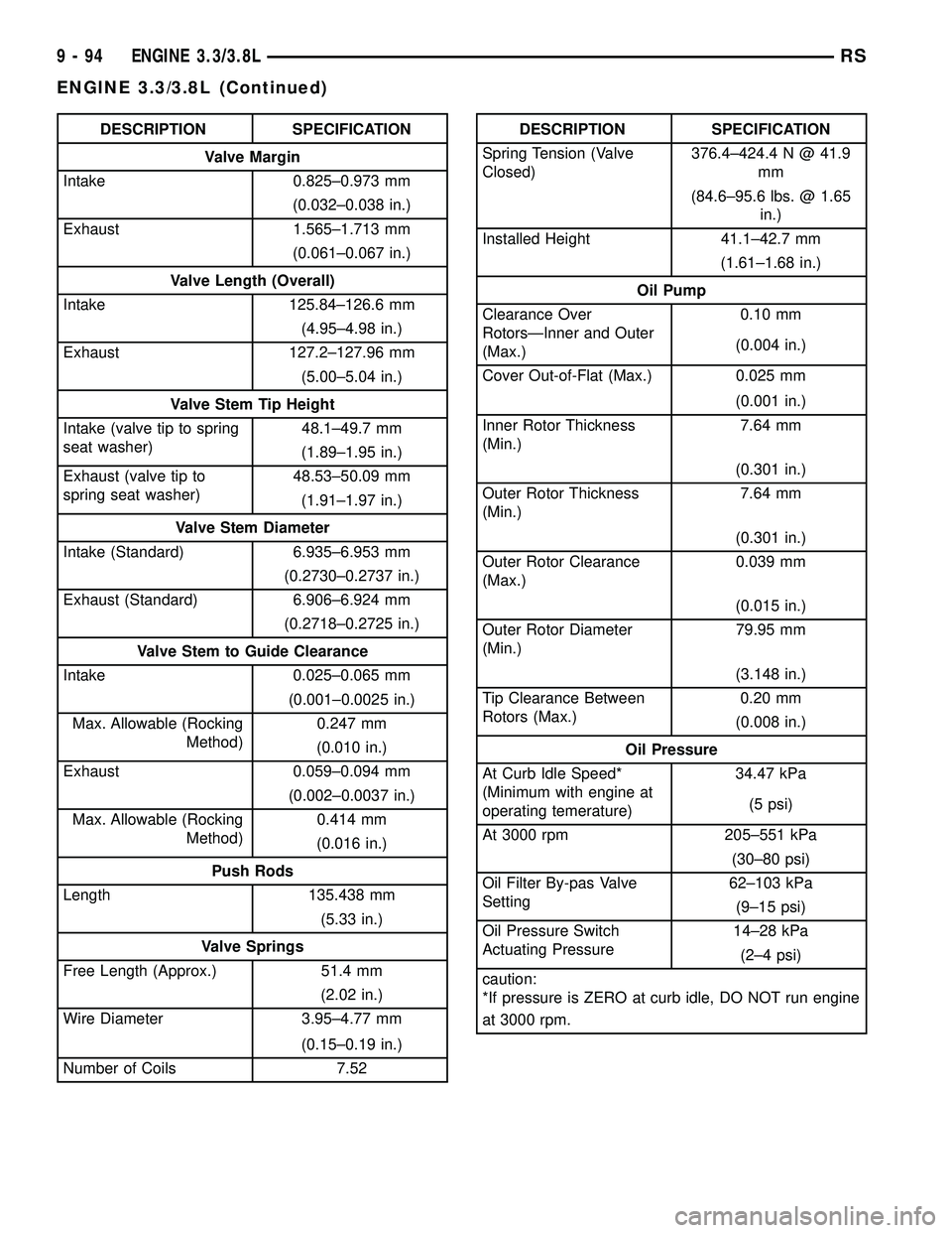
DESCRIPTION SPECIFICATION
Valve Margin
Intake 0.825±0.973 mm
(0.032±0.038 in.)
Exhaust 1.565±1.713 mm
(0.061±0.067 in.)
Valve Length (Overall)
Intake 125.84±126.6 mm
(4.95±4.98 in.)
Exhaust 127.2±127.96 mm
(5.00±5.04 in.)
Valve Stem Tip Height
Intake (valve tip to spring
seat washer)48.1±49.7 mm
(1.89±1.95 in.)
Exhaust (valve tip to
spring seat washer)48.53±50.09 mm
(1.91±1.97 in.)
Valve Stem Diameter
Intake (Standard) 6.935±6.953 mm
(0.2730±0.2737 in.)
Exhaust (Standard) 6.906±6.924 mm
(0.2718±0.2725 in.)
Valve Stem to Guide Clearance
Intake 0.025±0.065 mm
(0.001±0.0025 in.)
Max. Allowable (Rocking
Method)0.247 mm
(0.010 in.)
Exhaust 0.059±0.094 mm
(0.002±0.0037 in.)
Max. Allowable (Rocking
Method)0.414 mm
(0.016 in.)
Push Rods
Length 135.438 mm
(5.33 in.)
Valve Springs
Free Length (Approx.) 51.4 mm
(2.02 in.)
Wire Diameter 3.95±4.77 mm
(0.15±0.19 in.)
Number of Coils 7.52DESCRIPTION SPECIFICATION
Spring Tension (Valve
Closed)376.4±424.4 N @ 41.9
mm
(84.6±95.6 lbs. @ 1.65
in.)
Installed Height 41.1±42.7 mm
(1.61±1.68 in.)
Oil Pump
Clearance Over
RotorsÐInner and Outer
(Max.)0.10 mm
(0.004 in.)
Cover Out-of-Flat (Max.) 0.025 mm
(0.001 in.)
Inner Rotor Thickness
(Min.)7.64 mm
(0.301 in.)
Outer Rotor Thickness
(Min.)7.64 mm
(0.301 in.)
Outer Rotor Clearance
(Max.)0.039 mm
(0.015 in.)
Outer Rotor Diameter
(Min.)79.95 mm
(3.148 in.)
Tip Clearance Between
Rotors (Max.)0.20 mm
(0.008 in.)
Oil Pressure
At Curb Idle Speed*
(Minimum with engine at
operating temerature)34.47 kPa
(5 psi)
At 3000 rpm 205±551 kPa
(30±80 psi)
Oil Filter By-pas Valve
Setting62±103 kPa
(9±15 psi)
Oil Pressure Switch
Actuating Pressure14±28 kPa
(2±4 psi)
caution:
*If pressure is ZERO at curb idle, DO NOT run engine
at 3000 rpm.
9 - 94 ENGINE 3.3/3.8LRS
ENGINE 3.3/3.8L (Continued)
Page 1396 of 2585
AIR CLEANER HOUSING
REMOVAL
(1) Disconnect the negative battery cable.
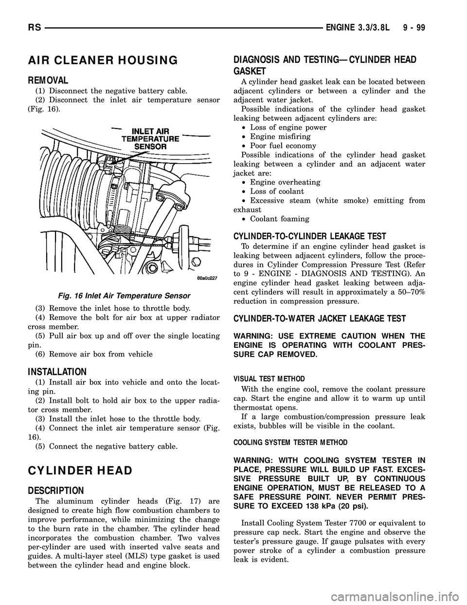
(2) Disconnect the inlet air temperature sensor
(Fig. 16).
(3) Remove the inlet hose to throttle body.
(4) Remove the bolt for air box at upper radiator
cross member.
(5) Pull air box up and off over the single locating
pin.
(6) Remove air box from vehicle
INSTALLATION
(1) Install air box into vehicle and onto the locat-
ing pin.
(2) Install bolt to hold air box to the upper radia-
tor cross member.
(3) Install the inlet hose to the throttle body.
(4) Connect the inlet air temperature sensor (Fig.
16).
(5) Connect the negative battery cable.
CYLINDER HEAD
DESCRIPTION
The aluminum cylinder heads (Fig. 17) are
designed to create high flow combustion chambers to
improve performance, while minimizing the change
to the burn rate in the chamber. The cylinder head
incorporates the combustion chamber. Two valves
per-cylinder are used with inserted valve seats and
guides. A multi-layer steel (MLS) type gasket is used
between the cylinder head and engine block.
DIAGNOSIS AND TESTINGÐCYLINDER HEAD
GASKET
A cylinder head gasket leak can be located between
adjacent cylinders or between a cylinder and the
adjacent water jacket.
Possible indications of the cylinder head gasket
leaking between adjacent cylinders are:
²Loss of engine power
²Engine misfiring
²Poor fuel economy
Possible indications of the cylinder head gasket
leaking between a cylinder and an adjacent water
jacket are:
²Engine overheating
²Loss of coolant
²Excessive steam (white smoke) emitting from
exhaust
²Coolant foaming
CYLINDER-TO-CYLINDER LEAKAGE TEST
To determine if an engine cylinder head gasket is
leaking between adjacent cylinders, follow the proce-
dures in Cylinder Compression Pressure Test (Refer
to 9 - ENGINE - DIAGNOSIS AND TESTING). An
engine cylinder head gasket leaking between adja-
cent cylinders will result in approximately a 50±70%
reduction in compression pressure.
CYLINDER-TO-WATER JACKET LEAKAGE TEST
WARNING: USE EXTREME CAUTION WHEN THE
ENGINE IS OPERATING WITH COOLANT PRES-
SURE CAP REMOVED.
VISUAL TEST METHOD
With the engine cool, remove the coolant pressure
cap. Start the engine and allow it to warm up until
thermostat opens.
If a large combustion/compression pressure leak
exists, bubbles will be visible in the coolant.
COOLING SYSTEM TESTER METHOD
WARNING: WITH COOLING SYSTEM TESTER IN
PLACE, PRESSURE WILL BUILD UP FAST. EXCES-
SIVE PRESSURE BUILT UP, BY CONTINUOUS
ENGINE OPERATION, MUST BE RELEASED TO A
SAFE PRESSURE POINT. NEVER PERMIT PRES-
SURE TO EXCEED 138 kPa (20 psi).
Install Cooling System Tester 7700 or equivalent to
pressure cap neck. Start the engine and observe the
tester's pressure gauge. If gauge pulsates with every
power stroke of a cylinder a combustion pressure
leak is evident.
Fig. 16 Inlet Air Temperature Sensor
RSENGINE 3.3/3.8L9-99
Page 1404 of 2585
(3) Remove cylinder head cover(s). (Refer to 9 -
ENGINE/CYLINDER HEAD/CYLINDER HEAD
COVER(S) - REMOVAL)
(4) Remove rocker arms and shaft. (Refer to 9 -
ENGINE/CYLINDER HEAD/ROCKER ARMS -
REMOVAL)
(5) Rotate engine until the piston in the cylinder
bore requiring spring removal is at TDC.
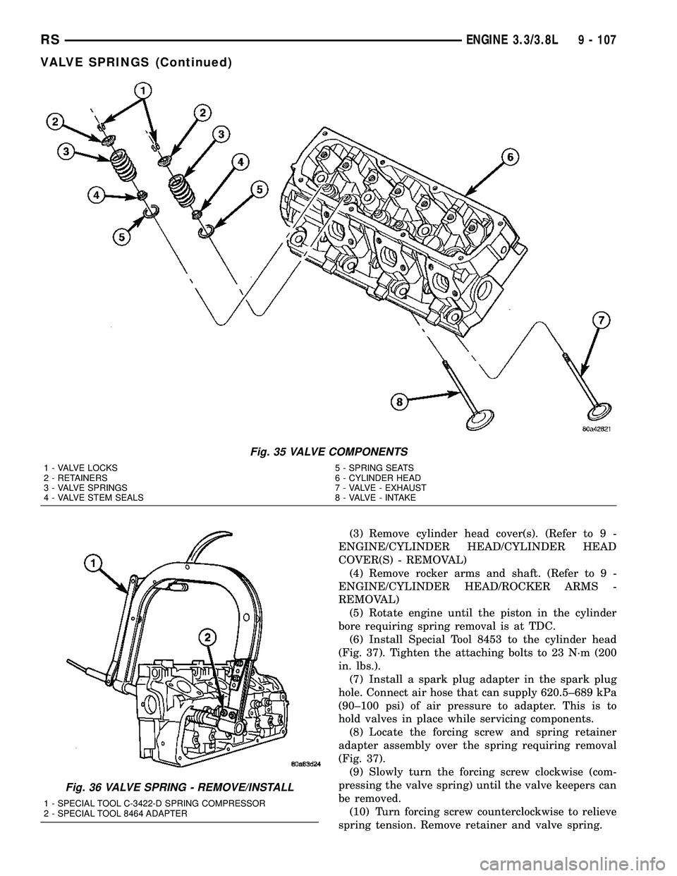
(6) Install Special Tool 8453 to the cylinder head
(Fig. 37). Tighten the attaching bolts to 23 N´m (200
in. lbs.).
(7) Install a spark plug adapter in the spark plug
hole. Connect air hose that can supply 620.5±689 kPa
(90±100 psi) of air pressure to adapter. This is to
hold valves in place while servicing components.
(8) Locate the forcing screw and spring retainer
adapter assembly over the spring requiring removal
(Fig. 37).
(9) Slowly turn the forcing screw clockwise (com-
pressing the valve spring) until the valve keepers can
be removed.
(10) Turn forcing screw counterclockwise to relieve
spring tension. Remove retainer and valve spring.
Fig. 35 VALVE COMPONENTS
1 - VALVE LOCKS 5 - SPRING SEATS
2 - RETAINERS 6 - CYLINDER HEAD
3 - VALVE SPRINGS 7 - VALVE - EXHAUST
4 - VALVE STEM SEALS 8 - VALVE - INTAKE
Fig. 36 VALVE SPRING - REMOVE/INSTALL
1 - SPECIAL TOOL C-3422-D SPRING COMPRESSOR
2 - SPECIAL TOOL 8464 ADAPTER
RSENGINE 3.3/3.8L9 - 107
VALVE SPRINGS (Continued)
Page 1438 of 2585
(7) Lower vehicle and install oil dipstick.
(8) Connect negative cable to battery.
(9) Fill crankcase with oil to proper level.
OIL PRESSURE RELIEF VALVE
REMOVAL
(1) Remove oil pan (Refer to 9 - ENGINE/LUBRI-
CATION/OIL PAN - REMOVAL).
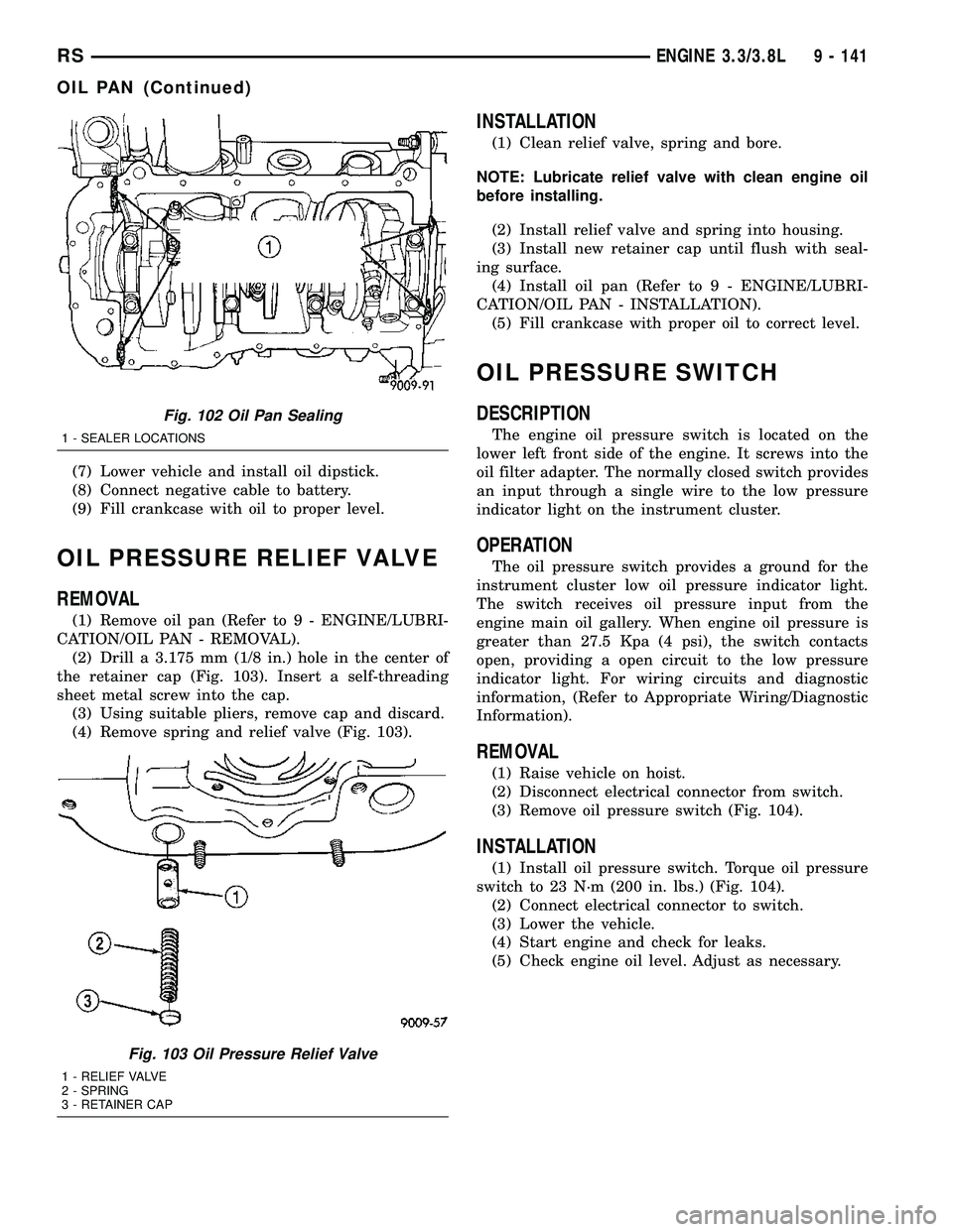
(2) Drill a 3.175 mm (1/8 in.) hole in the center of
the retainer cap (Fig. 103). Insert a self-threading
sheet metal screw into the cap.
(3) Using suitable pliers, remove cap and discard.
(4) Remove spring and relief valve (Fig. 103).
INSTALLATION
(1) Clean relief valve, spring and bore.
NOTE: Lubricate relief valve with clean engine oil
before installing.
(2) Install relief valve and spring into housing.
(3) Install new retainer cap until flush with seal-
ing surface.
(4) Install oil pan (Refer to 9 - ENGINE/LUBRI-
CATION/OIL PAN - INSTALLATION).
(5) Fill crankcase with proper oil to correct level.
OIL PRESSURE SWITCH
DESCRIPTION
The engine oil pressure switch is located on the
lower left front side of the engine. It screws into the
oil filter adapter. The normally closed switch provides
an input through a single wire to the low pressure
indicator light on the instrument cluster.
OPERATION
The oil pressure switch provides a ground for the
instrument cluster low oil pressure indicator light.
The switch receives oil pressure input from the
engine main oil gallery. When engine oil pressure is
greater than 27.5 Kpa (4 psi), the switch contacts
open, providing a open circuit to the low pressure
indicator light. For wiring circuits and diagnostic
information, (Refer to Appropriate Wiring/Diagnostic
Information).
REMOVAL
(1) Raise vehicle on hoist.
(2) Disconnect electrical connector from switch.
(3) Remove oil pressure switch (Fig. 104).
INSTALLATION
(1) Install oil pressure switch. Torque oil pressure
switch to 23 N´m (200 in. lbs.) (Fig. 104).
(2) Connect electrical connector to switch.
(3) Lower the vehicle.
(4) Start engine and check for leaks.
(5) Check engine oil level. Adjust as necessary.
Fig. 102 Oil Pan Sealing
1 - SEALER LOCATIONS
Fig. 103 Oil Pressure Relief Valve
1 - RELIEF VALVE
2 - SPRING
3 - RETAINER CAP
RSENGINE 3.3/3.8L9 - 141
OIL PAN (Continued)
Page 1456 of 2585

ENGINE
TABLE OF CONTENTS
page page
ENGINE 2.4L SUPPLEMENT.................. 1ENGINE 3.3/3.8L SUPPLEMENT............. 10
ENGINE 2.4L SUPPLEMENT
TABLE OF CONTENTS
page page
ENGINE 2.4L SUPPLEMENT
SPECIFICATIONS - 2.4L ENGINE............1
CRANKSHAFT
STANDARD PROCEDURE - CRANKSHAFT
ENDPLAY ............................6REMOVAL - CRANKSHAFT.................6
INSPECTION...........................7
INSTALLATION - CRANKSHAFT.............7
ENGINE 2.4L SUPPLEMENT
SPECIFICATIONS - 2.4L ENGINE
GENERAL SPECIFICATIONS
DESCRIPTION SPECIFICATION
Type In-Line OHV, DOHC
Number of
Cylinders4
Firing Order 1-3-4-2
Compression
Ratio9.5:1
Max. Variation
Between
Cylinders25%
Metric Standard
Displacement 2.4 Liters 148 cu. in.
Bore 87.5 mm 3.445 in.
Stroke 101.0 mm 3.976 in.
Compression
Pressure1172-1551 kPa 170-225 psi
CYLINDER BLOCK
DESCRIPTION SPECIFICATIONS
Metric Standard
Cylinder Bore
Diameter87.4924 -
87.5076 mm3.4446 - 3.4452
in.
Out-of-Round
(Max.)0.051 mm 0.002 in.
Taper (Max.) 0.051 mm 0.002 in.
RSENGINE9s-1
Page 1460 of 2585
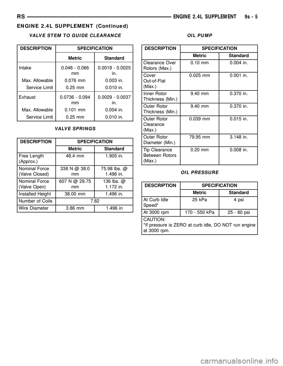
VALVE STEM TO GUIDE CLEARANCE
DESCRIPTION SPECIFICATION
Metric Standard
Intake 0.048 - 0.066
mm0.0018 - 0.0025
in.
Max. Allowable 0.076 mm 0.003 in.
Service Limit 0.25 mm 0.010 in.
Exhaust 0.0736 - 0.094
mm0.0029 - 0.0037
in.
Max. Allowable 0.101 mm 0.004 in.
Service Limit 0.25 mm 0.010 in.
VALVE SPRINGS
DESCRIPTION SPECIFICATION
Metric Standard
Free Length
(Approx.)48.4 mm 1.905 in.
Nominal Force
(Valve Closed)338 N @ 38.0
mm75.98 lbs. @
1.496 in.
Nominal Force
(Valve Open)607 N @ 29.75
mm136 lbs. @
1.172 in.
Installed Height 38.00 mm 1.496 in.
Number of Coils 7.82
Wire Diameter 3.86 mm 1.496 in
OIL PUMP
DESCRIPTION SPECIFICATION
Metric Standard
Clearance Over
Rotors (Max.)0.10 mm 0.004 in.
Cover
Out-of-Flat
(Max.)0.025 mm 0.001 in.
Inner Rotor
Thickness (Min.)9.40 mm 0.370 in.
Outer Rotor
Thickness (Min.)9.40 mm 0.370 in.
Outer Rotor
Clearance
(Max.)0.039 mm 0.015 in.
Outer Rotor
Diameter (Min.)79.95 mm 3.148 in.
Tip Clearance
Between Rotors
(Max.)0.20 mm 0.008 in.
OIL PRESSURE
DESCRIPTION SPECIFICATION
Metric Standard
At Curb Idle
Speed*25 kPa 4 psi
At 3000 rpm 170 - 550 kPa 25 - 80 psi
CAUTION:
*If pressure is ZERO at curb idle, DO NOT run engine
at 3000 rpm.
RSENGINE 2.4L SUPPLEMENT9s-5
ENGINE 2.4L SUPPLEMENT (Continued)
Page 1466 of 2585
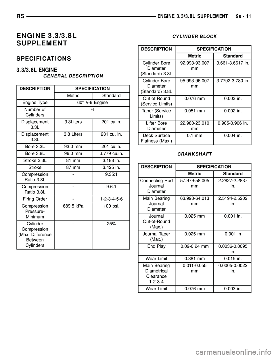
ENGINE 3.3/3.8L
SUPPLEMENT
SPECIFICATIONS
3.3/3.8L ENGINE
GENERAL DESCRIPTION
DESCRIPTION SPECIFICATION
Metric Standard
Engine Type 60É V-6 Engine
Number of
Cylinders6
Displacement
3.3L3.3Liters 201 cu.in.
Displacement
3.8L3.8 Liters 231 cu. in.
Bore 3.3L 93.0 mm 201 cu.in.
Bore 3.8L 96.0 mm 3.779 cu.in.
Stroke 3.3L 81 mm 3.188 in.
Stroke 87 mm 3.425 in.
Compression
Ratio 3.3L- 9.35:1
Compression
Ratio 3.8L- 9.6:1
Firing Order - 1-2-3-4-5-6
Compression
Pressure-
Minimum689.5 kPa 100 psi.
Cylinder
Compression
(Max. Difference
Between
Cylinders- 25%
CYLINDER BLOCK
DESCRIPTION SPECIFICATION
Metric Standard
Cylinder Bore
Diameter
(Standard) 3.3L92.993-93.007
mm3.661-3.6617 in.
Cylinder Bore
Diameter
(Standard) 3.8L95.993-96.007
mm3.7792-3.780 in.
Out of Round
(Service Limits)0.076 mm 0.003 in.
Taper (Service
Limits)0.051 mm 0.002 in.
Lifter Bore
Diameter22.980-23.010
mm0.905-0.906 in.
Deck Surface
Flatness (Max.)0.1 mm 0.004 in.
CRANKSHAFT
DESCRIPTION SPECIFICATION
Metric Standard
Connecting Rod
Journal
Diameter57.979-58.005
mm2.2827-2.2837
in.
Main Bearing
Journal
Diameter63.993-64.013
mm2.5194-2.5202
in.
Journal
Out-of-Round
(Max.)0.025 mm 0.001 in.
Journal Taper
(Max.)0.025 mm 0.001 in
End Play 0.09-0.24 mm 0.0036-0.0095
in.
Wear Limit 0.381 mm 0.015 in.
Main Bearing
Diametrical
Clearance
1-2-3-40.011-0.055
mm0.0005-0.0022
in.
Wear Limit 0.076 mm 0.003 in.
RSENGINE 3.3/3.8L SUPPLEMENT9s-11
Page 1470 of 2585
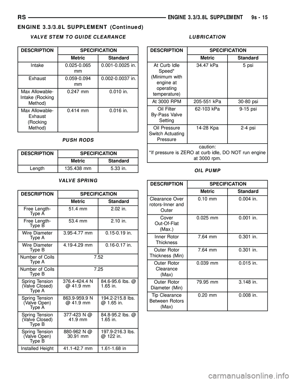
VALVE STEM TO GUIDE CLEARANCE
DESCRIPTION SPECIFICATION
Metric Standard
Intake 0.025-0.065
mm0.001-0.0025 in.
Exhaust 0.059-0.094
mm0.002-0.0037 in.
Max Allowable-
Intake (Rocking
Method)0.247 mm 0.010 in.
Max Allowable-
Exhaust
(Rocking
Method)0.414 mm 0.016 in.
PUSH RODS
DESCRIPTION SPECIFICATION
Metric Standard
Length 135.438 mm 5.33 in.
VALVE SPRING
DESCRIPTION SPECIFICATION
Metric Standard
Free Length-
Type A51.4 mm 2.02 in.
Free Length-
Type B53.4 mm 2.10 in.
Wire Diameter
Type A3.95-4.77 mm 0.15-0.19 in.
Wire Diameter
Type B4.19-4.29 mm 0.16-0.17 in.
Number of Coils
Type A7.52
Number of Coils
Type B7.25
Spring Tension
(Valve Closed)
Type A376.4-424.4 N
@ 41.9 mm84.6-95.6 lbs. @
1.65 in.
Spring Tension
(Valve Open)
Type A863.9-959.9 N
@ 41.9 mm194.2-215.8 lbs.
@ 1.65 in.
Spring Tension
(Valve Closed)
Type B377-423 N @
41.9 mm84.8-95.2 lbs. @
1.65 in.
Spring Tension
(Valve Open)
Type B880-962 N @
30.91 mm197.9-216.3 lbs.
@ 122 in.
Installed Height 41.1-42.7 mm 1.61-1.68 in
LUBRICATION
DESCRIPTION SPECIFICATION
Metric Standard
At Curb Idle
Speed*
(Minimum with
engine at
operating
temperature)34.47 kPa 5 psi
At 3000 RPM 205-551 kPa 30-80 psi
Oil Filter
By-Pass Valve
Setting62-103 kPa 9-15 psi
Oil Pressure
Switch Actuating
Pressure14-28 Kpa 2-4 psi
caution:
*If pressure is ZERO at curb idle, DO NOT run engine
at 3000 rpm.
OIL PUMP
DESCRIPTION SPECIFICATION
Metric Standard
Clearance Over
rotors-Inner and
Outer0.10 mm 0.004 in.
Cover
Out-Of-Flat
(Max.)0.025 mm 0.001 in.
Inner Rotor
Thickness7.64 mm 0.301 in.
Outer Rotor
Thickness (Min)7.64 mm 0.301 in.
Outer Rotor
Clearance
(Max)0.039 mm 0.015 in.
Outer Rotor
Diameter (Min)79.95 mm 3.148 in.
Tip Clearance
Between Rotors
(Max)0.20 mm 0.008 in.
RSENGINE 3.3/3.8L SUPPLEMENT9s-15
ENGINE 3.3/3.8L SUPPLEMENT (Continued)