2004 CHRYSLER VOYAGER psi
[x] Cancel search: psiPage 1472 of 2585
CYLINDER-TO-WATER JACKET LEAKAGE TEST
WARNING: USE EXTREME CAUTION WHEN THE
ENGINE IS OPERATING WITH COOLANT PRES-
SURE CAP REMOVED.
VISUAL TEST METHOD
With the engine cool, remove the coolant pressure
cap. Start the engine and allow it to warm up until
thermostat opens.
If a large combustion/compression pressure leak
exists, bubbles will be visible in the coolant.
COOLING SYSTEM TESTER METHOD
WARNING: WITH COOLING SYSTEM TESTER IN
PLACE, PRESSURE WILL BUILD UP FAST. EXCES-
SIVE PRESSURE BUILT UP, BY CONTINUOUS
ENGINE OPERATION, MUST BE RELEASED TO A
SAFE PRESSURE POINT. NEVER PERMIT PRES-
SURE TO EXCEED 138 kPa (20 psi).
Install Cooling System Tester 7700 or equivalent to
pressure cap neck. Start the engine and observe the
tester's pressure gauge. If gauge pulsates with every
power stroke of a cylinder a combustion pressure
leak is evident.
CHEMICAL TEST METHOD
Combustion leaks into the cooling system can also
be checked by using Bloc-Chek Kit C-3685-A or
equivalent. Perform test following the procedures
supplied with the tool kit.
REMOVAL - CYLINDER HEAD
(1) Drain the cooling system. (Refer to 7 - COOL-
ING - STANDARD PROCEDURE)
(2) Disconnect negative cable from battery.
(3) Remove upper and lower intake manifolds.
(Refer to 9 - ENGINE/MANIFOLDS/INTAKE MANI-
FOLD - REMOVAL)
WARNING: INTAKE MANIFOLD GASKET IS MADE
OF VERY THIN METAL AND MAY CAUSE PER-
SONAL INJURY, HANDLE WITH CARE.
(4) Remove the cylinder head covers. (Refer to 9 -
ENGINE/CYLINDER HEAD/CYLINDER HEAD
COVER(S) - REMOVAL)
(5) Remove the spark plugs from cylinder head.
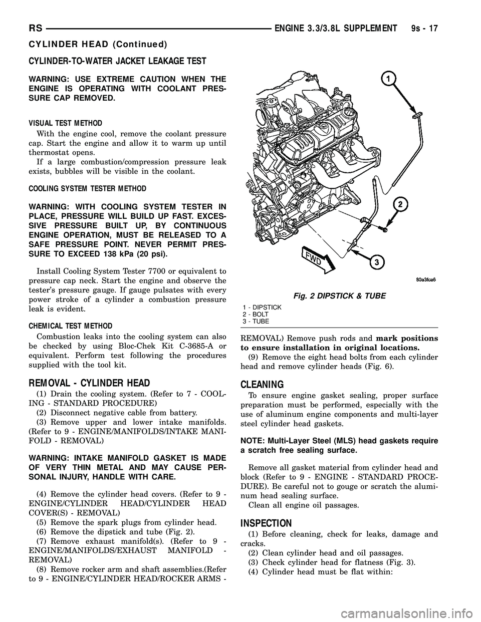
(6) Remove the dipstick and tube (Fig. 2).
(7) Remove exhaust manifold(s). (Refer to 9 -
ENGINE/MANIFOLDS/EXHAUST MANIFOLD -
REMOVAL)
(8) Remove rocker arm and shaft assemblies.(Refer
to 9 - ENGINE/CYLINDER HEAD/ROCKER ARMS -REMOVAL) Remove push rods andmark positions
to ensure installation in original locations.
(9) Remove the eight head bolts from each cylinder
head and remove cylinder heads (Fig. 6).
CLEANING
To ensure engine gasket sealing, proper surface
preparation must be performed, especially with the
use of aluminum engine components and multi-layer
steel cylinder head gaskets.
NOTE: Multi-Layer Steel (MLS) head gaskets require
a scratch free sealing surface.
Remove all gasket material from cylinder head and
block (Refer to 9 - ENGINE - STANDARD PROCE-
DURE). Be careful not to gouge or scratch the alumi-
num head sealing surface.
Clean all engine oil passages.
INSPECTION
(1) Before cleaning, check for leaks, damage and
cracks.
(2) Clean cylinder head and oil passages.
(3) Check cylinder head for flatness (Fig. 3).
(4) Cylinder head must be flat within:
Fig. 2 DIPSTICK & TUBE
1 - DIPSTICK
2 - BOLT
3 - TUBE
RSENGINE 3.3/3.8L SUPPLEMENT9s-17
CYLINDER HEAD (Continued)
Page 1480 of 2585
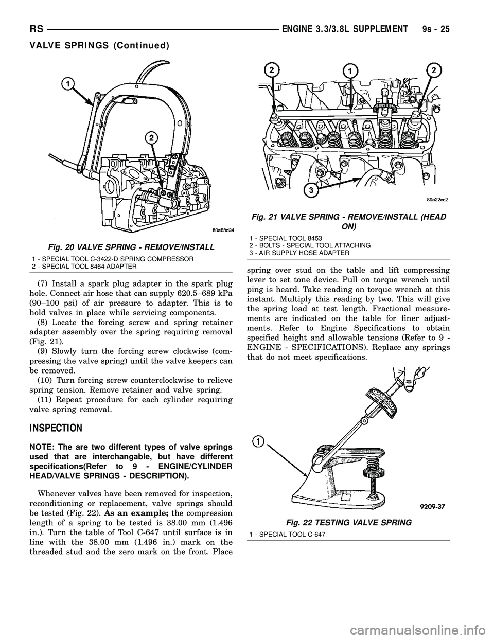
(7) Install a spark plug adapter in the spark plug
hole. Connect air hose that can supply 620.5±689 kPa
(90±100 psi) of air pressure to adapter. This is to
hold valves in place while servicing components.
(8) Locate the forcing screw and spring retainer
adapter assembly over the spring requiring removal
(Fig. 21).
(9) Slowly turn the forcing screw clockwise (com-
pressing the valve spring) until the valve keepers can
be removed.
(10) Turn forcing screw counterclockwise to relieve
spring tension. Remove retainer and valve spring.
(11) Repeat procedure for each cylinder requiring
valve spring removal.
INSPECTION
NOTE: The are two different types of valve springs
used that are interchangable, but have different
specifications(Refer to 9 - ENGINE/CYLINDER
HEAD/VALVE SPRINGS - DESCRIPTION).
Whenever valves have been removed for inspection,
reconditioning or replacement, valve springs should
be tested (Fig. 22).As an example;the compression
length of a spring to be tested is 38.00 mm (1.496
in.). Turn the table of Tool C-647 until surface is in
line with the 38.00 mm (1.496 in.) mark on the
threaded stud and the zero mark on the front. Placespring over stud on the table and lift compressing
lever to set tone device. Pull on torque wrench until
ping is heard. Take reading on torque wrench at this
instant. Multiply this reading by two. This will give
the spring load at test length. Fractional measure-
ments are indicated on the table for finer adjust-
ments. Refer to Engine Specifications to obtain
specified height and allowable tensions (Refer to 9 -
ENGINE - SPECIFICATIONS). Replace any springs
that do not meet specifications.
Fig. 20 VALVE SPRING - REMOVE/INSTALL
1 - SPECIAL TOOL C-3422-D SPRING COMPRESSOR
2 - SPECIAL TOOL 8464 ADAPTER
Fig. 21 VALVE SPRING - REMOVE/INSTALL (HEAD
ON)
1 - SPECIAL TOOL 8453
2 - BOLTS - SPECIAL TOOL ATTACHING
3 - AIR SUPPLY HOSE ADAPTER
Fig. 22 TESTING VALVE SPRING
1 - SPECIAL TOOL C-647
RSENGINE 3.3/3.8L SUPPLEMENT9s-25
VALVE SPRINGS (Continued)
Page 1487 of 2585
DIAGNOSIS AND TESTING
DIAGNOSIS AND TESTING - EXCESSIVE
EXHAUST SYSTEM NOISE
CONDITION POSSIBLE CAUSES CORRECTION
EXCESSIVE EXHAUST NOISE
(UNDER HOOD)1. Exhaust manifold cracked or
broken.1. Replace manifold.
2. Manifold to cylinder head leak. 2. Tighten manifold and/or replace
gasket.
3. EGR Valve to manifold gasket
leakage.3. Tighten fasteners or replace
gasket.
4. EGR Valve to EGR tube gasket
leakage.4. Tighten fasteners or replace
gasket.
5. EGR tube to manifold tube
leakage.5. Tighten tube nut.
6. Exhaust flex-joint to manifold
leak.6. Tighten joint fasteners and/or
replace gasket.
7. Exhaust flex-joint. 7. Replace catalytic converter
assembly.
8. Pipe and shell noise from front
exhaust pipe.8. Characteristic of single wall pipe.
EXCESSIVE EXHAUST NOISE 1. Leak at exhaust pipe joints. 1. Tighten clamps at leaking joints.
2. Burned or rusted out muffler
assembly or exhaust pipe.2. Replace muffler resonator tailpipe
assembly or exhaust pipe with
catalytic converter assembly.
3. Burned or rusted out resonator. 3. Replace muffler resonator tailpipe
assembly.
4. Restriction in exhaust system. 4. Perform Exhaust System
Restriction Check. Replace
component as necessary.
5. Converter material in muffler. 5. Replace muffler and converter
assemblies. Check fuel injection and
ignition systems for proper
operation.
DIAGNOSIS AND TESTING - EXHAUST SYSTEM
RESTRICTION CHECK
Exhaust system restriction can be checked by mea-
suring back pressure using the DRB IIItand PEP
module pressure tester.
WARNING: THE NORMAL OPERATING TEMPERA-
TURE OF THE EXHAUST SYSTEM IS VERY HIGH.
THEREFORE, NEVER WORK AROUND OR ATTEMPT
TO SERVICE ANY PART OF THE EXHAUST SYSTEM
UNTIL IT IS COOLED. SPECIAL CARE SHOULD BE
TAKEN WHEN WORKING NEAR THE CATALYTIC
CONVERTER. THE TEMPERATURE OF THE CON-VERTER RISES TO A HIGH LEVEL AFTER A SHORT
PERIOD OF ENGINE OPERATION TIME.
NOTE: For Special Tool identification, (Refer to 11 -
EXHAUST SYSTEM - SPECIAL TOOLS).
(1) Disconnect and remove the upstream (before
catalytic converter) oxygen sensor. (Refer to 14 -
FUEL SYSTEM/FUEL INJECTION/O2 SENSOR -
REMOVAL)
(2) Install the Exhaust Back Pressure Fitting
Adaptor CH8519.
(3) Connect the Low Pressure Sensor (15 psi)
CH7063 to the back pressure fitting.
11 - 2 EXHAUST SYSTEMRS
EXHAUST SYSTEM (Continued)
Page 1488 of 2585
(4) Following the PEP module instruction manual,
connect all required cables to the DRB IIItand PEP
module. Select the available menu options on the
DRBIIItdisplay screen for using the digital pressure
gauge function.
(5) Apply the park brake and start the engine.
(6) With transmission in Park or Neutral, raise
engine speed to 2000 RPM. Monitor the pressure
readings on the DRBIIIt. Back pressure should not
exceed specified limit. Refer to specification in table
below EXHAUST BACK PRESSURE LIMITS .
(7) If pressure exceeds maximum limits, inspect
exhaust system for restricted component. For further
catalytic converter inspection procedures, (Refer to 11
- EXHAUST SYSTEM/CATALYTIC CONVERTER -
INSPECTION). Replace component(s) as necessary.
EXHAUST BACK PRESSURE LIMITS
Exhaust Back Pressure Limit (Max)
Vehicle in Park/Neutral
(no load) @2000 RPM3.45 Kpa (0.5 psi)
INSPECTION
Inspect the exhaust pipes, catalytic converters,
muffler, and resonators for cracked joints, broken
welds and corrosion damage that would result in a
leaking exhaust system. Inspect the clamps, support
brackets, and insulators for cracks and corrosion
damage.
NOTE: Slip joint band clamps are spot welded to
exhaust system. If a band clamp must be replaced,
the spot weld must be ground off.
ADJUSTMENTS
A misaligned exhaust system is usually indicated
by a vibration, rattling noise, or binding of exhaust
system components. These noises are sometimes hard
to distinguish from other chassis noises. Inspect
exhaust system for broken, damaged or loose compo-
nents such as; clamps, heat shields, isolators, and
hanger brackets. Replace or tighten as necessary. It
is important that exhaust system clearances and
alignment be maintained.
Perform the following procedures to align the
exhaust system:
(1) Loosen band clamp at catalytic converter pipe
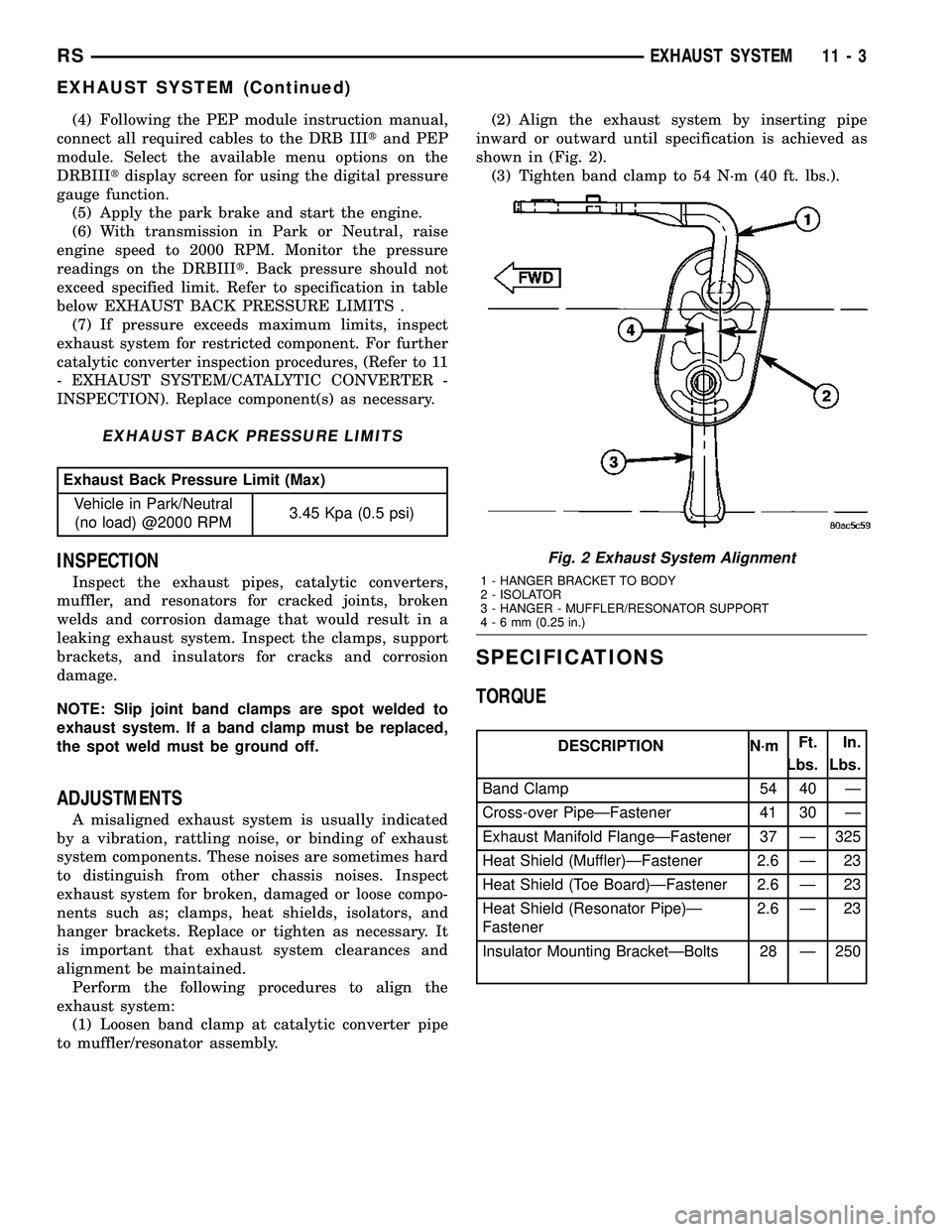
to muffler/resonator assembly.(2) Align the exhaust system by inserting pipe
inward or outward until specification is achieved as
shown in (Fig. 2).
(3) Tighten band clamp to 54 N´m (40 ft. lbs.).
SPECIFICATIONS
TORQUE
DESCRIPTION N´mFt.
Lbs.In.
Lbs.
Band Clamp 54 40 Ð
Cross-over PipeÐFastener 41 30 Ð
Exhaust Manifold FlangeÐFastener 37 Ð 325
Heat Shield (Muffler)ÐFastener 2.6 Ð 23
Heat Shield (Toe Board)ÐFastener 2.6 Ð 23
Heat Shield (Resonator Pipe)Ð
Fastener2.6 Ð 23
Insulator Mounting BracketÐBolts 28 Ð 250
Fig. 2 Exhaust System Alignment
1 - HANGER BRACKET TO BODY
2 - ISOLATOR
3 - HANGER - MUFFLER/RESONATOR SUPPORT
4-6mm(0.25 in.)
RSEXHAUST SYSTEM11-3
EXHAUST SYSTEM (Continued)
Page 1510 of 2585
NOTE: WRAP SHOP TOWELS AROUND HOSES TO
CATCH ANY GASOLINE SPILLAGE.
(11) Drain fuel tank into holding tank or a prop-
erly labeledGasolinesafety container.
WARNING: GASOLINE OR GASOLINE VAPORS ARE
HIGHLY FLAMMABLE. A FIRE COULD OCCUR IF AN
IGNITION SOURCE IS PRESENT. NEVER DRAIN ORSTORE GASOLINE OR DIESEL FUEL IN AN OPEN
CONTAINER, DUE TO THE POSSIBILITY OF FIRE
OR EXPLOSION. THIS MAY RESULT IN PERSONAL
INJURY OR DEATH.
(12) If fuel pump module removal is necessary,
refer to Fuel Pump Module Removal/Installation in
this section.
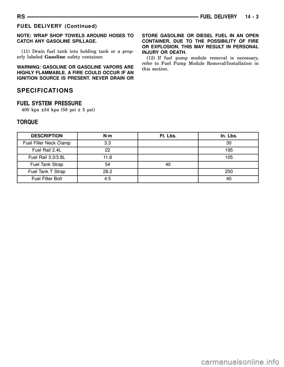
SPECIFICATIONS
FUEL SYSTEM PRESSURE
400 kpa 34 kpa (58 psi 5 psi)
TORQUE
DESCRIPTION N´m Ft. Lbs. In. Lbs.
Fuel Filler Neck Clamp 3.3 30
Fuel Rail 2.4L 22 195
Fuel Rail 3.3/3.8L 11.8 105
Fuel Tank Strap 54 40
Fuel Tank T Strap 28.2 250
Fuel Filter Bolt 4.5 40
RSFUEL DELIVERY14-3
FUEL DELIVERY (Continued)
Page 1514 of 2585
nated fuel in this system. If it is necessary to replace
these lines/tubes/hoses, use new original equipment
lines/tubes/hoses.
If equipped:The hose clamps used to secure rub-
ber hoses on vehicles are of a special rolled edge con-
struction. This construction is used to prevent the
edge of the clamp from cutting into the hose. Only
these rolled edge type clamps may be used in this
system. All other types of clamps may cut into the
hoses and cause leaks.
Use new original equipment type hose clamps.
STANDARD PROCEDURE - HOSES AND CLAMP
Inspect all hose connections (clamps and quick con-
nect fittings) for completeness and leaks. Replace
cracked, scuffed, or swelled hoses. Replace hoses that
rub against other vehicle components or show sign of
wear.
Fuel injected vehicles use specially constructed
hoses. When replacing hoses, only use hoses marked
EFM/EFI.
When installing hoses, ensure that they are routed
away from contact with other vehicle components
that could rub against them and cause failure. Avoid
contact with clamps or other components that cause
abrasions or scuffing. Ensure that rubber hoses are
properly routed and avoid heat sources.
The hose clamps have rolled edges to prevent the
clamp from cutting into the hose. Only use clamps
that are original equipment or equivalent. Other
types of clamps may cut into the hoses and cause
high pressure fuel leaks. Tighten hose clamps to 1
N´m (9 in. lbs.) torque.
Inspect all hose connections such as clamps, cou-
plings and fittings to make sure they are secure and
leaks are not present. The component should be
replaced immediately if there is any evidence of deg-
radation that could result in failure.
Never attempt to repair a plastic fuel line/tube.
Replace as necessary.
Avoid contact of any fuel tubes/hoses with other
vehicle components that could cause abrasions or
scuffing. Be sure that the plastic fuel lines/tubes are
properly routed to prevent pinching and to avoid heat
sources.
FUEL PRESSURE REGULATOR
OPERATION
The fuel system uses a nonadjustable pressure reg-
ulator that maintains fuel system pressure at
approximately 400 34 kPa (58 5 psi). The fuel
pressure regulator contains a diaphragm, calibrated
spring and a fuel return valve. The spring pushes
down on the diaphragm and closes off the fuel returnport. System fuel pressure reflects the amount of fuel
pressure required to open the return port.
The pressure regulator is a mechanical device that
is NOT controlled by the PCM or engine vacuum.
REMOVAL
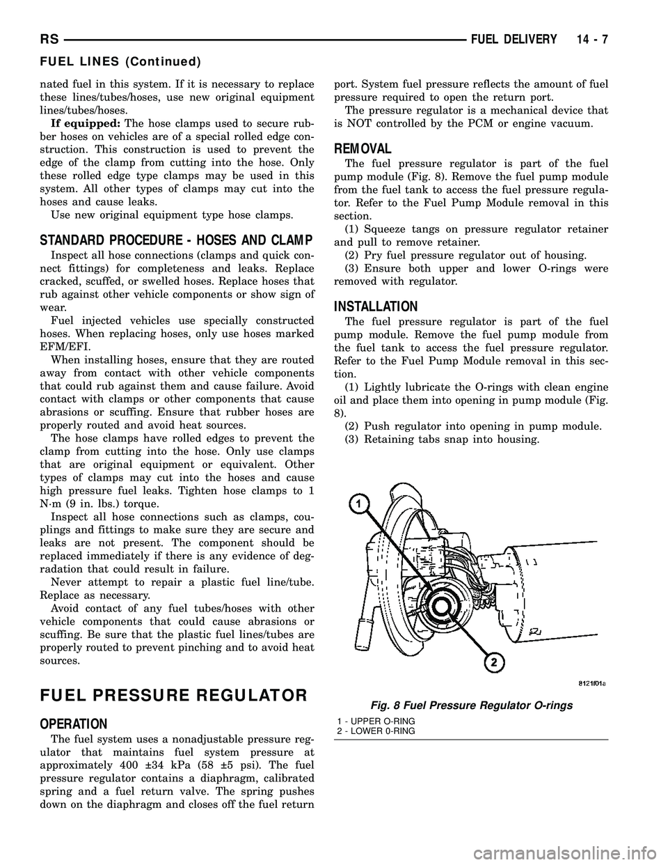
The fuel pressure regulator is part of the fuel
pump module (Fig. 8). Remove the fuel pump module
from the fuel tank to access the fuel pressure regula-
tor. Refer to the Fuel Pump Module removal in this
section.
(1) Squeeze tangs on pressure regulator retainer
and pull to remove retainer.
(2) Pry fuel pressure regulator out of housing.
(3) Ensure both upper and lower O-rings were
removed with regulator.
INSTALLATION
The fuel pressure regulator is part of the fuel
pump module. Remove the fuel pump module from
the fuel tank to access the fuel pressure regulator.
Refer to the Fuel Pump Module removal in this sec-
tion.
(1) Lightly lubricate the O-rings with clean engine
oil and place them into opening in pump module (Fig.
8).
(2) Push regulator into opening in pump module.
(3) Retaining tabs snap into housing.
Fig. 8 Fuel Pressure Regulator O-rings
1 - UPPER O-RING
2 - LOWER 0-RING
RSFUEL DELIVERY14-7
FUEL LINES (Continued)
Page 1515 of 2585
FUEL PUMP
DESCRIPTION
The electric fuel pump is located in and is part of
the fuel pump module. It is a positive displacement,
gerotor type, immersible pump with a permanent
magnet electric motor. The fuel pump module is sus-
pended in fuel in the fuel tank.
OPERATION
The pump draws fuel through a strainer and
pushes it through the motor to the outlet. The pump
contains a check valve. The valve, in the pump out-
let, maintains pump pressure during engine off con-
ditions, for a short while. It is normal for fuel
pressure to drop to zero after cooldown. The fuel
pump relay provides voltage to the fuel pump. The
fuel pump has a maximum deadheaded pressure out-
put of approximately 880 kPa (130 psi). The regula-
tor adjusts fuel system pressure to approximately
400 kpa 34 kpa (58 psi 5 psi).
FUEL PUMP MODULE
DESCRIPTION
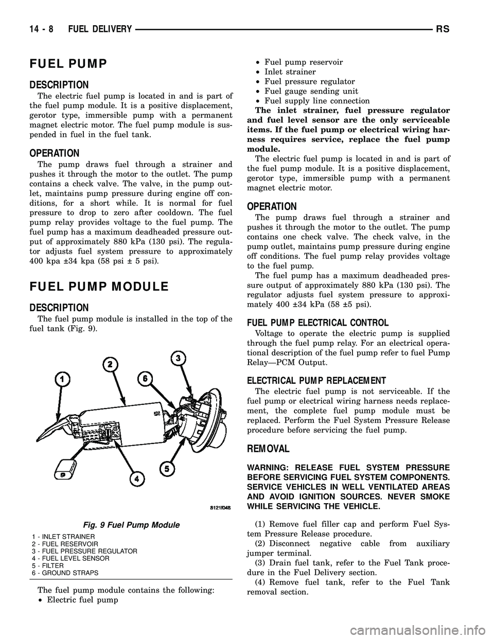
The fuel pump module is installed in the top of the
fuel tank (Fig. 9).
The fuel pump module contains the following:
²Electric fuel pump²Fuel pump reservoir
²Inlet strainer
²Fuel pressure regulator
²Fuel gauge sending unit
²Fuel supply line connection
The inlet strainer, fuel pressure regulator
and fuel level sensor are the only serviceable
items. If the fuel pump or electrical wiring har-
ness requires service, replace the fuel pump
module.
The electric fuel pump is located in and is part of
the fuel pump module. It is a positive displacement,
gerotor type, immersible pump with a permanent
magnet electric motor.
OPERATION
The pump draws fuel through a strainer and
pushes it through the motor to the outlet. The pump
contains one check valve. The check valve, in the
pump outlet, maintains pump pressure during engine
off conditions. The fuel pump relay provides voltage
to the fuel pump.
The fuel pump has a maximum deadheaded pres-
sure output of approximately 880 kPa (130 psi). The
regulator adjusts fuel system pressure to approxi-
mately 400 34 kPa (58 5 psi).
FUEL PUMP ELECTRICAL CONTROL
Voltage to operate the electric pump is supplied
through the fuel pump relay. For an electrical opera-
tional description of the fuel pump refer to fuel Pump
RelayÐPCM Output.
ELECTRICAL PUMP REPLACEMENT
The electric fuel pump is not serviceable. If the
fuel pump or electrical wiring harness needs replace-
ment, the complete fuel pump module must be
replaced. Perform the Fuel System Pressure Release
procedure before servicing the fuel pump.
REMOVAL
WARNING: RELEASE FUEL SYSTEM PRESSURE
BEFORE SERVICING FUEL SYSTEM COMPONENTS.
SERVICE VEHICLES IN WELL VENTILATED AREAS
AND AVOID IGNITION SOURCES. NEVER SMOKE
WHILE SERVICING THE VEHICLE.
(1) Remove fuel filler cap and perform Fuel Sys-
tem Pressure Release procedure.
(2) Disconnect negative cable from auxiliary
jumper terminal.
(3) Drain fuel tank, refer to the Fuel Tank proce-
dure in the Fuel Delivery section.
(4) Remove fuel tank, refer to the Fuel Tank
removal section.
Fig. 9 Fuel Pump Module
1 - INLET STRAINER
2 - FUEL RESERVOIR
3 - FUEL PRESSURE REGULATOR
4 - FUEL LEVEL SENSOR
5 - FILTER
6 - GROUND STRAPS
14 - 8 FUEL DELIVERYRS
Page 1537 of 2585
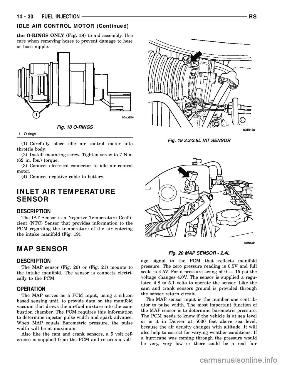
the O-RINGS ONLY (Fig. 18)to aid assembly. Use
care when removing hoses to prevent damage to hose
or hose nipple.
(1) Carefully place idle air control motor into
throttle body.
(2) Install mounting screw. Tighten screw to 7 N´m
(62 in. lbs.) torque.
(3) Connect electrical connector to idle air control
motor.
(4) Connect negative cable to battery.
INLET AIR TEMPERATURE
SENSOR
DESCRIPTION
The IAT Sensor is a Negative Temperature Coeffi-
cient (NTC) Sensor that provides information to the
PCM regarding the temperature of the air entering
the intake manifold (Fig. 19).
MAP SENSOR
DESCRIPTION
The MAP sensor (Fig. 20) or (Fig. 21) mounts to
the intake manifold. The sensor is connects electri-
cally to the PCM.
OPERATION
The MAP serves as a PCM input, using a silicon
based sensing unit, to provide data on the manifold
vacuum that draws the air/fuel mixture into the com-
bustion chamber. The PCM requires this information
to determine injector pulse width and spark advance.
When MAP equals Barometric pressure, the pulse
width will be at maximum.
Also like the cam and crank sensors, a 5 volt ref-
erence is supplied from the PCM and returns a volt-age signal to the PCM that reflects manifold
pressure. The zero pressure reading is 0.5V and full
scale is 4.5V. For a pressure swing of0Ð15psithe
voltage changes 4.0V. The sensor is supplied a regu-
lated 4.8 to 5.1 volts to operate the sensor. Like the
cam and crank sensors ground is provided through
the sensor return circuit.
The MAP sensor input is the number one contrib-
utor to pulse width. The most important function of
the MAP sensor is to determine barometric pressure.
The PCM needs to know if the vehicle is at sea level
or is it in Denver at 5000 feet above sea level,
because the air density changes with altitude. It will
also help to correct for varying weather conditions. If
a hurricane was coming through the pressure would
be very, very low or there could be a real fair
Fig. 18 O-RINGS
1 - O-rings
Fig. 19 3.3/3.8L IAT SENSOR
Fig. 20 MAP SENSOR - 2.4L
14 - 30 FUEL INJECTIONRS
IDLE AIR CONTROL MOTOR (Continued)