Page 360 of 510
4 - 76
ENGTRANSMISSION, SHIFT CAM AND SHIFT FORK
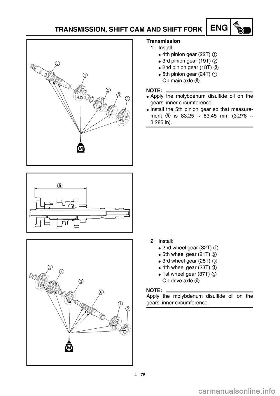
Transmission
1. Install:
�4th pinion gear (22T) 1
�3rd pinion gear (19T) 2
�2nd pinion gear (18T) 3
�5th pinion gear (24T) 4
On main axle 5.
NOTE:
�Apply the molybdenum disulfide oil on the
gears’ inner circumference.
�Install the 5th pinion gear so that measure-
ment a is 83.25 ~ 83.45 mm (3.278 ~
3.285 in).
2. Install:
�2nd wheel gear (32T) 1
�5th wheel gear (21T) 2
�3rd wheel gear (25T) 3
�4th wheel gear (23T) 4
�1st wheel gear (37T) 5
On drive axle 6.
NOTE:
Apply the molybdenum disulfide oil on the
gears’ inner circumference.
Page 362 of 510
4 - 77
ENGTRANSMISSION, SHIFT CAM AND SHIFT FORK
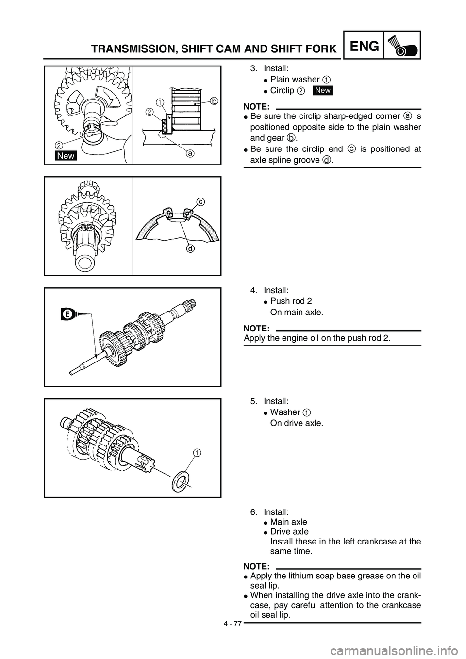
3. Install:
�Plain washer 1
�Circlip 2
NOTE:
�Be sure the circlip sharp-edged corner a is
positioned opposite side to the plain washer
and gear b.
�Be sure the circlip end c is positioned at
axle spline groove d.
New
4. Install:
�Push rod 2
On main axle.
NOTE:
Apply the engine oil on the push rod 2.
5. Install:
�Washer 1
On drive axle.
6. Install:
�Main axle
�Drive axle
Install these in the left crankcase at the
same time.
NOTE:
�Apply the lithium soap base grease on the oil
seal lip.
�When installing the drive axle into the crank-
case, pay careful attention to the crankcase
oil seal lip.
Page 364 of 510
4 - 78
ENGTRANSMISSION, SHIFT CAM AND SHIFT FORK
Shift cam and shift fork
1. Install:
�Shift fork 1 (L) 1
�Shift fork 2 (C) 2
�Shift fork 3 (R) 3
NOTE:
�Mesh the shift fork #1 (L) with the 2nd wheel
gear and #3 (R) with the 4th wheel gear on
the drive axle.
�Mesh the shift fork #2 (C) with the 3rd pinion
gear on the main axle.
2. Install:
�Shift cam 1
NOTE:
Apply the engine oil on the shift cam.
3. Install:
�Shift fork guide bar 1 (short) 1
�Shift fork guide bar 2 (long) 2
NOTE:
�Apply the engine oil on the guide bars.
�Be sure the long bar is inserted into the shift
forks #1 and #3 and the short one into #2.
4. Check:
�Shifter operation
�Transmission operation
Unsmooth operation → Repair.
Page 366 of 510
5 - 1
CHAS
FRONT WHEEL AND FRONT BRAKE (TT-R125)
EC500000
CHASSIS
FRONT WHEEL AND FRONT BRAKE (TT-R125)
Extent of removal:
1
Front wheel removal
2
Wheel bearing removal
3
Brake shoe plate assembly removal and disassembly
Extent of removal Order Part name Q’ty Remarks
Preparation for removal
FRONT WHEEL AND DRUM
BRAKE
Hold the machine by placing the
suitable stand under the engine.
WARNING
Support the machine securely so there is no
danger of it falling over.
1 Brake cable holder 1
2 Brake cable 1 Disconnect at the lever side, first.
3 Axle nut 1
4 Wheel axle 1
5 Front wheel 1
6 Collar set 1
7 Brake shoe plate assembly 1
8 Oil seal 1
9 Wheel bearing 2 Refer to “REMOVAL POINTS”.
10Spacer
1
2
3
1
Page 370 of 510
5 - 3
CHAS
FRONT WHEEL AND FRONT BRAKE (TT-R125)
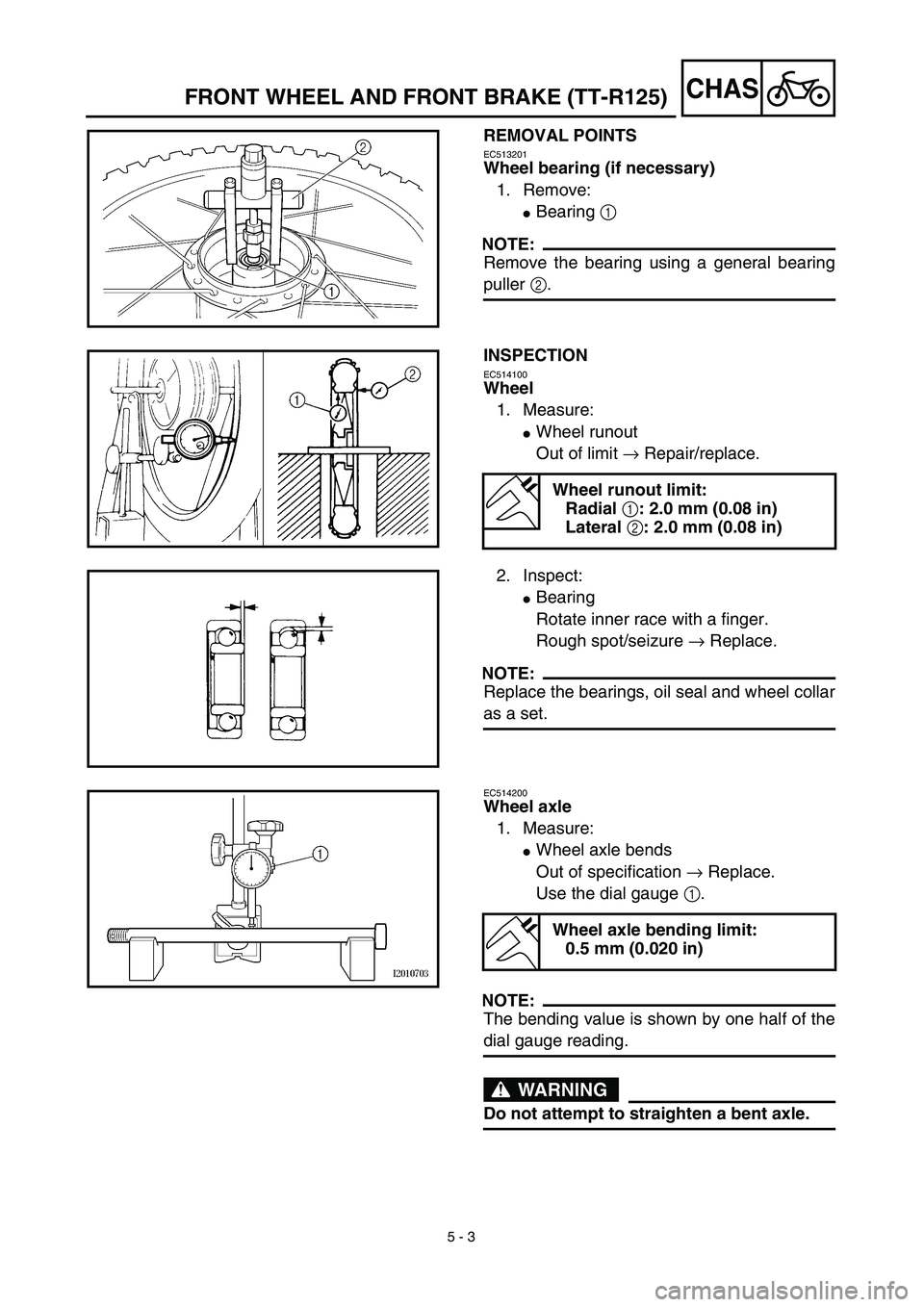
REMOVAL POINTS
EC513201
Wheel bearing (if necessary)
1. Remove:
�
Bearing
1
NOTE:
Remove the bearing using a general bearing
puller
2
.
INSPECTION
EC514100
Wheel
1. Measure:
�
Wheel runout
Out of limit
→
Repair/replace.
Wheel runout limit:
Radial
1
: 2.0 mm (0.08 in)
Lateral
2
: 2.0 mm (0.08 in)
2. Inspect:
�
Bearing
Rotate inner race with a finger.
Rough spot/seizure
→
Replace.
NOTE:
Replace the bearings, oil seal and wheel collar
as a set.
EC514200
Wheel axle
1. Measure:
�
Wheel axle bends
Out of specification
→
Replace.
Use the dial gauge
1
.
NOTE:
The bending value is shown by one half of the
dial gauge reading.
WARNING
Do not attempt to straighten a bent axle.
Wheel axle bending limit:
0.5 mm (0.020 in)
Page 371 of 510

5 - 3
CHAS
DEMONTAGEPUNKTE
Radlager (falls erforderlich)
1. Demontieren:
�
Lager
1
HINWEIS:
Lager mit einem herkömmlichen Lageraustrei-
ber
2
demontieren.
PRÜFEN
Rad
1. M")
5 - 3
CHAS
DEMONTAGEPUNKTE
Radlager (falls erforderlich)
1. Demontieren:
�
Lager
1
HINWEIS:
Lager mit einem herkömmlichen Lageraustrei-
ber
2
demontieren.
PRÜFEN
Rad
1. Messen:
�
Max. Schlag
Unvorschriftsmäßig
→
Reparieren/
erneuern.
2. Prüfen:
�
Lager
Inneren Lagerlaufring mit einem Finger
drehen.
Rauheit/Lager fest
→
Erneuern.
HINWEIS:
Lager, Dichtring und Paßhülse satzweise
erneuern.
Maximal zulässiger Schlag
Max. Höhenschlag
1
: 2,0 mm
Max. Seitenschlag
2
: 2,0 mm
Radachse
1. Messen:
�
Radachsenbiegung
Unvorschriftsmäßig
→
Erneuern.
Meßuhr
1
verwenden.
HINWEIS:
Der Verzug ergibt sich aus der Hälfte des von
der Meßuhr angezeigten Wertes.
WARNUNG
Niemals versuchen, eine verbogene Achse
zu richten.
Maximal zulässige Achsbiegung
0,5 mm
ROUE AVANT ET FREIN AVANT (TT-R125)
VORDERRAD UND VORDERRADBREMSE (TT-R125)
PIÈCES À DÉPOSER
Roulement de roue (si nécessaire)
1. Déposer:
�
Roulement
1
N.B.:
Déposer le roulement à l’aide de l’extracteur de
roulements universel
2
.
INSPECTION
Roue
1. Mesurer:
�
Déformation de la roue
Hors spécifications
→
Réparer ou rempla-
cer.
2. Examiner:
�
Roulement
Faire tourner la cage interne à l’aide d’un
doigt.
Dureté/grippage
→
Remplacer.
N.B.:
Remplacer à la fois les roulements, la bague d’étan-
chéité et l’entretoise épaulée.
Limite de voile de roue:
Radial
1
: 2,0 mm (0,08 in)
Latéral
2
: 2,0 mm (0,08 in)
Axe de roue
1. Mesurer:
�
Déformations de l’axe de roue
Hors spécifications
→
Remplacer.
Utiliser un comparateur à cadran
1
.
N.B.:
Pour obtenir la déformation, il faut diviser en deux
la valeur affichée sur le comparateur à cadran.
AVERTISSEMENT
Ne pas tenter de redresser un axe déformé.
Limite de déformation d’axe de roue:
0,5 mm (0,020 in)
Page 372 of 510
5 - 4
CHAS
FRONT WHEEL AND FRONT BRAKE (TT-R125)
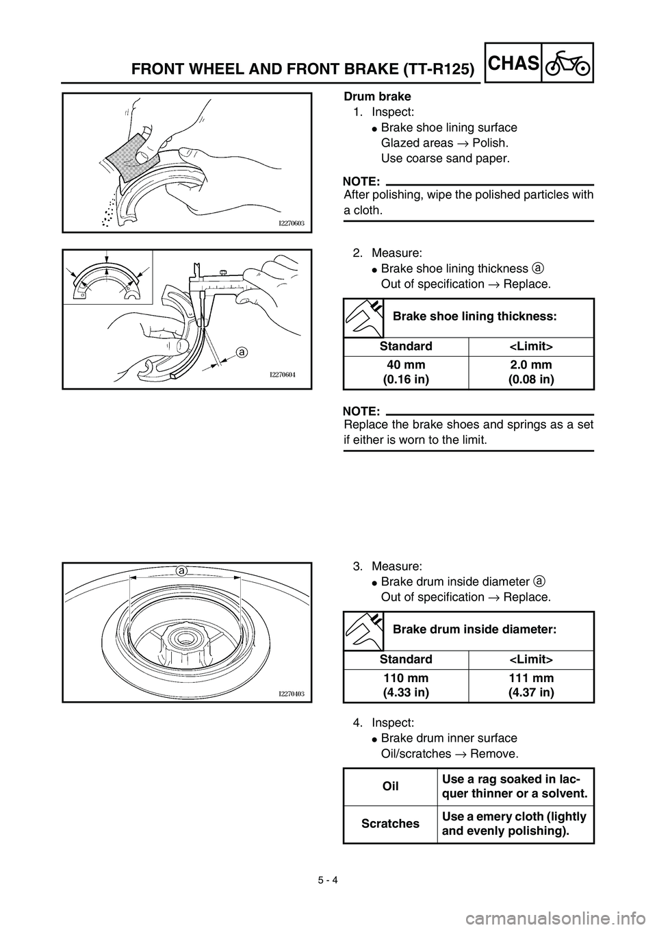
Drum brake
1. Inspect:
�
Brake shoe lining surface
Glazed areas
→
Polish.
Use coarse sand paper.
NOTE:
After polishing, wipe the polished particles with
a cloth.
2. Measure:
�
Brake shoe lining thickness
a
Out of specification
→
Replace.
NOTE:
Replace the brake shoes and springs as a set
if either is worn to the limit.
Brake shoe lining thickness:
Standard
40 mm
(0.16 in)2.0 mm
(0.08 in)
3. Measure:
�
Brake drum inside diameter
a
Out of specification
→
Replace.
Brake drum inside diameter:
Standard
110 mm
(4.33 in)111 mm
(4.37 in)
4. Inspect:
�
Brake drum inner surface
Oil/scratches
→
Remove.
OilUse a rag soaked in lac-
quer thinner or a solvent.
ScratchesUse a emery cloth (lightly
and evenly polishing).
Page 373 of 510

5 - 4
CHAS
Trommelbremse
1. Kontrollieren:
�
Bremsbelag-Oberfläche
Glasige Oberfläche
→
Anschleifen.
Grobes Sandpapier verwenden.
HINWEIS:
Nach dem Anschleifen die Schleifpartikel mit")
5 - 4
CHAS
Trommelbremse
1. Kontrollieren:
�
Bremsbelag-Oberfläche
Glasige Oberfläche
→
Anschleifen.
Grobes Sandpapier verwenden.
HINWEIS:
Nach dem Anschleifen die Schleifpartikel mit
einem Lappen abwischen.
2. Messen:
�
Trommelbremsbelag-Stärke
a
Unvorschriftsmäßig
→
Erneuern.
HINWEIS:
Bremsbeläge und Federn immer komplett
erneuern, auch wenn nur ein Belag die Grenz-
wert erreicht hat.
Trommelbremsbelag-Stärke
Standard
40 mm 2,0 mm
3. Messen:
�
Bremstrommel-Innendurchmesser a
Unvorschriftsmäßig → Erneuern.
4. Kontrollieren:
�Bremstrommel-Oberfläche (innen)
Öl/Kratzer → Entfernen.
Bremstrommel-Innendurchmes-
ser
Standard
110 mm 111 mm
ÖlEinen mit Verdünner oder
einem Lösungsmittel
getränkten Lappen ver-
wenden.
KratzerSchmirgelleinen verwen-
den (vorsichtig und
gleichmäßig polieren).
ROUE AVANT ET FREIN AVANT (TT-R125)
VORDERRAD UND VORDERRADBREMSE (TT-R125)
Frein à tambour
1. Examiner:
�Surface de garniture de mâchoire de frein
Zones brillantes → Poncer.
Utiliser du papier de verre à gros grains.
N.B.:
Après ce ponçage, éliminer les particules avec un
chiffon.
2. Mesurer:
�Épaisseur de garniture de mâchoire de frein a
Hors spécifications → Remplacer.
N.B.:
Remplacer à la fois les mâchoires de frein et les
ressorts si la limite d’une de ces pièces est atteinte.
Épaisseur de garniture de mâchoire
de frein:
Standard
40 mm
(0,16 in)2,0 mm
(0,08 in)
3. Mesurer:
�Diamètre intérieur de tambour de frein a
Hors spécifications → Remplacer.
4. Examiner:
�Surface intérieure du tambour de frein
Taches d’huile/rayures → Éliminer.
Diamètre intérieur de tambour de
frein:
Standard
110 mm
(4,33 in)111 mm
(4,37 in)
HuileSe servir d’un chiffon
imbibé de diluant pour pein-
ture ou de dissolvant.
RayuresUtiliser de la toile émeri
(polir légèrement et unifor-
mément).


5 - 1
CHAS
FRONT WHEEL AND FRONT BRAKE (TT-R125)
EC500000
CHASSIS
FRONT WHEEL AND FRONT BRAKE (TT-R125)
Extent of removal:
1
Front wheel removal
2
Wheel bearing removal
3
Brake")